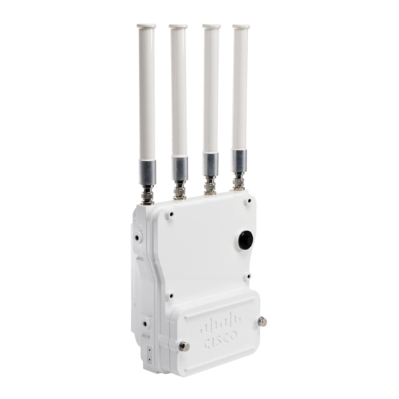
Cisco Catalyst IW6300 Heavy Duty Series Installing Manual
Hide thumbs
Also See for Catalyst IW6300 Heavy Duty Series:
- Hardware installation manual (84 pages) ,
- Getting started (20 pages)
Advertisement
Installing the Access Point
This chapter describes how to install the access point.
•
•
•
•
•
•
•
Mounting on a Wall or a Pole
This section provides instructions for the physical installation of your access points. Personnel installing the
access point must understand wireless access points and bridging techniques and grounding methods.
Caution
All installation methods for mounting an access point on any wall surface is subject to the acceptance of local
jurisdiction.
Installation Option
The Cisco Catalyst IW6300 Heavy Duty Series Access Points are installed using the pole mount installation
kit (IOT-ACCPMK), which is used for pole or wall installations.
Warning
Only trained and qualified personnel should be allowed to install, replace, or service this equipment. Statement
1030
Warning
Installation of the equipment must comply with local and national electrical codes. Statement 1074
Refer to these sections for installation details:
Mounting on a Wall or a Pole, on page 1
Working with the Access Cover, on page 13
Installing External Antennas, on page 15
Grounding the Access Point , on page 19
Using the Reset Button, on page 20
Powering the Access Point, on page 20
Performing Maintenance, on page 27
Installing the Access Point
1
Advertisement

Related Manuals for Cisco Catalyst IW6300 Heavy Duty Series


Summary of Contents for Cisco Catalyst IW6300 Heavy Duty Series
-
Page 1: Table Of Contents
All installation methods for mounting an access point on any wall surface is subject to the acceptance of local jurisdiction. Installation Option The Cisco Catalyst IW6300 Heavy Duty Series Access Points are installed using the pole mount installation kit (IOT-ACCPMK), which is used for pole or wall installations. Warning Only trained and qualified personnel should be allowed to install, replace, or service this equipment. - Page 2 Access Point Mounting Orientation Access Point Mounting Orientation Cisco Catalyst IW6300 Heavy Duty Series Access Points are only intended to be installed vertically with the antenna ports facing upwards. If you want the antennas to face down, you should use the Extender Bracket Kit (IOT-ACCPMK-LB=).
- Page 3 Installing the Access Point Mounting the Access Point on a Wall Figure 2: Unit Dimension - Side Mounting the Access Point on a Wall The optional pole mount kit contains a mounting bracket for wall mounting. You can use the mounting bracket as a template to mark the positions of the mounting holes for your installation.
- Page 4 Installing the Access Point Mounting the Access Point on a Wall Materials Required Electric drill and standard screwdriver #6-AWG ground wire Shielded outdoor-rated Ethernet (CAT5e or better) cable Grounding block Grounding rod 13-mm box-end wrench or socket set Caution The mounting surface, attaching screws, and optional wall anchors must be able to support a 50-lb(22.7 kg) static weight.
- Page 5 Installing the Access Point Mounting the Access Point on a Wall Figure 4: Screw Hole Locations on the Mounting Bracket Mounting slots Hands-free attach point Mounting holes Second support bolt hole Step 2 Use four customer-supplied screws and optional screw anchors to attach the mounting plate to the mounting surface.
- Page 6 Mounting the Access Point on a Pole When installing an access point on a vertical pole, you should use the optional Cisco pole mount kit. The kit supports metal, wood, or fiberglass poles from 2 to 16 inches in diameter.
- Page 7 Installing the Access Point Assembling the Pole Clamp Bracket and the Mounting Bracket Figure 6: Pole Clamp Bracket Adjustment Hole Locations Pole size indicators Bolt holes for pole diameters • 2 to 6 inches (5.08 cm to 15.24 cm) (11 to 16 inches (27.94 cm to 40.64 cm) indicated) •...
- Page 8 Installing the Access Point Pole Mounting Figure 7: Assembled Pole Clamp Bracket and Strap Brackets M8 x1.25x16 bolts (with lock washers) Pole clamp bracket Strap bracket (shown positioned for 11 to 16 inch diameter pole) Step 2 Screw the M8 nut onto the pole clamp bracket support bolt, and tighten just enough to prevent the bolt from falling off.
- Page 9 Materials Required Vertical or streetlight Two 0.75-in (1.9 cm) stainless steel bands pole Banding strap tool (BAND IT) (Cisco AIR-BAND-INST-TL=) Ground lug (provided with access point) Crimping tool for ground lug, Panduit CT-720 with CD-720-1 die (http://onlinecatalog.panduit.com) #6 AWG ground wire...
- Page 10 Step 5 Tighten the metal bands using the banding strap tool (BAND IT) (Cisco AIR-BAND-INST-TL=) by following the operating instructions in the box with the tool. Ensure that the metal bands are as tight as possible.
- Page 11 Installing the Access Point Pole Mounting The access point should be positioned with the LEDs on the bottom to allow viewing from the Note ground and with the hinged cover facing out. Figure 10: Assembling Access Point to Hands-Free Attach Point with Top Support Bolts Top Support M8 x16 bolt hole Hands-free attach point Second M8 x16 bolt hole...
- Page 12 Installing the Access Point Pole Mounting Figure 11: Second Support Bolt Installation M8 x16 bolt Step 13 Ensure that the front of the access point is vertical, and tighten the four bolts to 13 to 15 ft lbs (17.6 to 20.3 Nm).
-
Page 13: Working With The Access Cover
(5.1 to 40.6 cm) diameter Mount bracket Stainless steel mounting straps Step 14 When using the Cisco Aironet Dual-Band Omnidirectional Antennas, connect them to the access point. Hand-tighten the antennas to the access point. Step 15 Continue with Grounding the Access Point , on page 19... - Page 14 Installing the Access Point Closing the Access Cover To open the access cover, follow these steps: Procedure Step 1 Use 0.5-in (13-mm) box-end wrench or socket set to unscrew the two bolts on the front cover of the unit. Only unscrew the bolts about 2 turns until they are easily turned by hand, and the bolts are resting on springs.
-
Page 15: Installing External Antennas
Installing the Access Point Installing External Antennas Installing External Antennas Note When operating in the 5GHz UNII-1 band, all Omni Directional antennas should be installed vertically, and all directional antennas should be installed with the main beam aimed parallel to or tilted down toward the horizon. - Page 16 Installing the Access Point Antenna Selection Examples Cisco Industrial Routers and Industrial Wireless Access Points Antenna Guide http://www.cisco.com/c/en/us/support/wireless/aironet-antennas-accessories/products-installation-guides-list.html Follow all safety precautions when installing the antennas. For information on safety, see Safety Precautions When Installing Antennas. Antenna Selection Examples The following examples list suggested antenna and RF accessory selections for typical installation scenarios.
- Page 17 Installing the Access Point Antenna Selection Examples Use Case Antennas Coaxial Cables Lightning Installation Antenna Arrestors and/or Mode Adapters Configuration Omnidirectional 1x 2.4 GHz 13 dBi 2x N(m) – N(m) cables: 2x N(m)-N(f) Connect the two 5 GHz Single band access on 5 GHz, Directional Antenna Lightning Arrestor...
- Page 18 In addition, the following guidelines apply for UL 50E compliance: • Type 4X indoor and outdoor compliant when used with Cisco cabling and antennas noted above. • Type 4X indoor and type 4 outdoor compliant with Cisco provided antennas noted above and installer provided type 4/UV compliant cable.
-
Page 19: Grounding The Access Point
Cisco does not recommend any third-party antennas, and Cisco Technical Assistance Center will not be able to provide any support for third-party antennas. Cisco’s FCC Part 15 compliance is only guaranteed with Cisco antennas or antennas that are of the same design and gain as Cisco antennas. -
Page 20: Using The Reset Button
Installing the Access Point Using the Reset Button Step 5 If necessary, strip the other end of the ground wire and connect it to a reliable earth ground, such as a grounding rod or an appropriate grounding point on a metal streetlight pole that is grounded. Using the Reset Button The access point has a reset button located on the right side of the unit (see the following figure). - Page 21 Installing the Access Point Connecting a Power Injector • IW-6300H-AC-x-K9: 85-264V~ maximum, marked 100-240V~, 50-60Hz, 1.3A • IW-6300H-DC-x–K9: 44 to 57Vdc, 1.2A • IW-6300H-DCW-x-K9: 10.8 to 36Vdc, 5.9A Note The marked DC input range is an absolute range. Do not apply tolerances. Note In all cases above, the AC branch circuit powering the access point must be limited to no more than 20A from the over-protection device supplied by the user.
- Page 22 To forward bridge traffic, add a switch between the power injector and controller. Refer to the latest Cisco Wireless Mesh Access Points, Design and Deployment Guide for more information. Step 3 Ensure that the antennas are connected and that a ground is attached to the access point before you apply power to the access point.
- Page 23 Installing the Access Point Connecting AC Power to IW-6300H-AC-x-K9 Step 6 Carefully insert the RJ-45 cable connector into the Ethernet port opening on the access point, and connect to the internal Ethernet connector. Step 7 Ensure that the antennas are connected to the access point before you apply power to the access point. Step 8 Route your Ethernet cable, and cut off any excess cable.
- Page 24 Installing the Access Point Connecting DC Power to IW-6300H-DCW-x-K9 Figure 16: Connecting Internal Ground and AC Power Connection for IW-6300H-AC-X-K9 Customer-supplied harness Terminal block Customer-supplied cable (ATEX only) Step 4 Use a wire stripper tool to remove the insulation from each wire. Remove only enough wire to provide a solid connection in the terminal block.
- Page 25 Installing the Access Point Connecting DC Power to IW-6300H-DCW-x-K9 Warning To reduce risk of electric shock, connect the unit only to DC power source that complies with the Safety Extra-Low Voltage (SELV) requirements in IEC 60950 based safety standards or ES1 requirements in IEC 62368 based safety standards.
- Page 26 Figure 18: Connecting Internal Ground and DC Power for IW-6300H-DC-x-K9 Terminal block Internal ground Step 4 Use a wire stripper tool to remove the insulation from each wire. Remove only enough wire to provide adequate crimp on to ring terminals (Cisco supplied). Installing the Access Point...
-
Page 27: Performing Maintenance
Installing the Access Point Performing Maintenance Step 5 Remove terminal strip screw and square washer. Connect DC line to terminal strip location. Tighten terminal strip screws to secure ring terminal and wire. Step 6 Secure DC input cord to wire tie anchor adjacent to terminal strip. Step 7 Check your work. - Page 28 Installing the Access Point Conducting Periodic Cleaning Installing the Access Point...