Table of Contents
Advertisement
Cisco IW3702 Access Point Getting Started Guide
Cisco IW3702 Access Point Getting Started Guide
2
Organization
2
Conventions
2
Overview
3
Installation
14
Antennas and RF Accessories
25
Configuration
48
Technical Specifications
63
Ports and Connectors
72
Related Documentation
75
Obtaining Documentation and Submitting a Service Request
75
Advertisement
Table of Contents

Related Manuals for Cisco IW3702


Summary of Contents for Cisco IW3702
- Page 1 Cisco IW3702 Access Point Getting Started Guide Cisco IW3702 Access Point Getting Started Guide Organization Conventions Overview Installation Antennas and RF Accessories Configuration Technical Specifications Ports and Connectors Related Documentation Obtaining Documentation and Submitting a Service Request...
-
Page 2: Cisco Iw3702 Access Point Getting Started Guide
Cisco IW3702 Access Point Getting Started Guide This guide documents the hardware features of the Cisco IW3702 access point. It describes the physical and performance characteristics of each access point, and explains how to install and configure an access point. -
Page 3: Overview
THESE INSTRUCTIONS Overview This document describes the Cisco IW3702 access point. The access point is an IEEE 802.11a/b/g/n/ac compliant, dual-band WiFi access point with external antennas. The access point is IP67 rated, ruggedized, and certified for on-board rail and outdoor use-cases such as train and trackside, mining, intelligent transportation systems, and smart city applications. -
Page 4: Access Point Models
• Rugged IP67 rated housing and -40 to 167°F (-40 to 75°C) operating temperature range (ambient—without solar loading or wind cooling) • Compact size for space constrained environments Access Point Models There are two access point models, based on antenna configuration. The following table lists the available IW3702 models. Table 1: Access Point Models Model Description... -
Page 5: Bottom And Top Panel Views
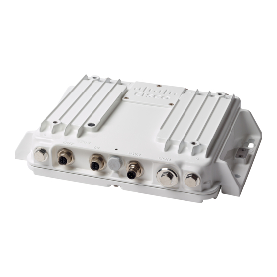
Bottom and Top Panel Views Figure 1: Cisco IW3702-2E-UXK9/IW3702-2E-x-K9 Bottom Panel View Status LED Power (PWR) connector Antenna port B Console (CON) port PoE OUT port Antenna port A PoE IN port Ground connection Protective vent port / Reset button (covered) - Page 6 Note There are four antenna ports on the Cisco IW3702-2E-UXK9/IW3702-2E-x-K9 model: two on the top and two on the bottom. Figure 2: Cisco IW3702-2E-UXK9/IW3702-2E-x-K9 Top Panel View Antenna port C Antenna port A Antenna port D Antenna port B...
- Page 7 Note There are four antenna ports on the Cisco IW3702-4E-UXK9/IW3702-4E-x-K9 model: all four connectors are on the top side. Figure 3: Cisco IW3702-4E-UXK9/IW3702-4E-x-K9 Bottom Panel View Status LED Power (PWR) connector PoE OUT port Console (CON) port PoE IN port...
-
Page 8: Bottom Panel Components
Figure 4: Cisco IW3702-4E-UXK9/IW3702-4E-x-K9 Top Panel View Antenna port C Antenna port B Antenna port A Antenna port D Bottom Panel Components This section describes the bottom panel components. Status LED The Status LEDs provide information on access point status, activity, and performance. The following table describes status LED... - Page 9 DRAM memory test in progress. DRAM memory test OK. Board initialization in progress. Initializing flash file system. Flash memory test OK. Initializing Ethernet. Ethernet OK. Starting Cisco IOS. Initialization successful. Client association status Green Normal operating condition but no wireless client association. Blue Normal operating condition with at least one wireless client association.
- Page 10 AP status when provisioned by Cisco Cycling red-green-off AP waiting to be primed. AirProvision Blinking white AP priming via Cisco NDP in progress. Blinking teal (for 15 seconds) AP upon successful connection to Cisco AirProvision. Blinking blue AP priming via Cisco AirProvision in progress.
- Page 11 Note When powering the access point: 1 Power can be supplied via DC input (PWR connector) or PoE inline (PoE IN port), but not both. 2 We recommend that you not use two power options concurrently, but no harm results if both are present.
-
Page 12: Top Panel Components
4 Torque the protective vent to 5-7 inch-lbs. Console Port You can connect the access point to a PC or laptop through the RJ45 CON port. The RJ45 CON port uses the Cisco console port RJ45-to-DB9 cable (Cisco PN 72-3383-01). -
Page 13: Management Options
• Cisco IOS command-line interface (CLI)—Configures the access point. You can access the CLI by directly connecting a PC to the console port, or you can access the CLI using a Telnet session from a remote management station. -
Page 14: Preparing For Installation
Preparing for Installation The following topics prepare you for installing the unit: Warnings These warnings are translated into several languages in the Regulatory Compliance and Safety Information for the Cisco IW3702 Access Point on Cisco.com. Danger Only trained and qualified personnel should be allowed to install, replace, or service this equipment. -
Page 15: Statement
Ultimate disposal of this product should be handled according to all national laws and regulations. Danger Statement 1040 To prevent the system from overheating, do not operate it in an area that exceeds the maximum Danger recommended ambient temperature of: 70°C Statement 1047 Installation of the equipment must comply with local and national electrical codes. - Page 16 Because the access point is a radio device, it is susceptible to common causes of interference that can reduce throughput and range. Follow these guidelines to ensure the best possible performance: • For information on planning and initially configuring your Cisco Mesh network, refer to the Cisco Wireless Mesh Access Points, Design and Deployment Guide.
-
Page 17: Unpacking The Components
• Install the access point in an area where structures, trees, or hills do not obstruct radio signals to and from the devices. • For information on priming a Cisco universal access point, see the Cisco Aironet Universal AP Priming and Cisco AirProvision User Guide at: http://www.cisco.com/c/en/us/td/docs/wireless/access_point/ux-ap/guide/uxap-mobapp-g.html... - Page 18 Note The M12 connector caps are installed on the ports for protection when the AP is shipped. Remove the caps before using the ports. See the following figure for the locations of each port with M12 cap. Figure 6: PoE and PWR Connectors With Caps PoE ports with caps PWR connector with cap To unpack the access point:...
-
Page 19: Mounting The Access Point
Mounting the Access Point For instructions about mounting the access point, see the Cisco IW3702 Access Point Mounting Guide Connecting the Protective Ground and Power Perform the following steps in order when connecting the access point to power and ground. - Page 20 The grounding kit also includes the oxide inhibitor, which is contained in a tube. Note To ground the access point: Procedure Step 1 Use a crimping tool to crimp a 6-AWG ground wire (not included in the grounding kit) to the ground lug. Step 2 Connect the supplied ground lug to the access point ground connection point using the supplied screws.
- Page 21 Ground connection Step 4 If necessary, strip the other end of the ground wire and connect it to a reliable earth ground such as a grounding rod or appropriate ground point on a grounded pole. Length of the ground cable should not exceed 1 meter, and 0.5 meter is preferred.
-
Page 22: Connecting The Antennas
Power cable and PWR connector Step 3 Connect the other end of the power cable to the DC power source using the power source wiring instructions. The PWR connector pinout descriptions are in Power Port, on page Connecting the Antennas Connect each antenna based on: •... -
Page 23: Connecting To Access Point Ports
Ethernet cables must have an internal shield around the signal wires. There must be a contiguous ground between the connector shell that interfaces with the IW3702 and the connector shell on the far end of the cable. Maximum cable length should not exceed 100 meters. - Page 24 Step 2 Connect the PoE IN cable to the PoE IN port, or the PoE OUT cable to the PoE OUT port by turning the cable clockwise, as shown in the following figure. Figure 8: Connecting to the PoE IN or PoE OUT Ports PoE OUT cable PoE IN cable When powered over the PoE IN port, PoE OUT functionality is not supported.
-
Page 25: Antennas And Rf Accessories
This section describes antennas, RF Accessories, and their configuration for the access point. Cisco recommends using a coax seal (such as CoaxSeal) for outdoor connections, to prevent moisture and other weathering elements from affecting performance. For more information on using coax seal on the N connector to cable or antenna interface, see the instructions on your antenna documents. - Page 26 Cisco PID Description Loss at 2.4 GHz Loss at 5.8 GHz CAB-L400-5-N-N N(m)-R/A to N(m)-STR, 0.5 dB 0.8 dB LMR-400-DB , 5ft RF cable Type: outdoor DB (direct burial) CAB-L400-5-N-NS N(m)-STR to N(m)-STR, 0.5 dB 0.8 dB LMR-400-DB , 5ft RF cable...
- Page 27 Cisco PID Description Loss at 2.4 GHz Loss at 5.8 GHz CAB-L400-20-N-R N(m)-R/A to RP-TNC(jack), 1.6 dB 2.5 dB LMR-400-DB, 20 ft RF cable Type: outdoor DB (direct burial) N(m)-R/A = N(male) right angle connector N(m)-STR = N(male) straight connector RP-TNC connectors used on cables specified in the table are straight.
-
Page 28: Examples Of Access Point And Antenna Deployment Configurations
The section provides examples of antenna installation configurations, including applicable accessories such as cables, lighting arrestors, and adapters. Indoor or Outdoor Cisco Aironet Dual-Band Omnidirectional Antenna and Access Point Table 7: Indoor or Outdoor Dual-Band Omnidirectional Antenna and Access Point... - Page 29 Outdoor Cisco Aironet Dual-Band Omnidirectional Antenna and Access Point for Remote and Indoor Use Scenario Table 8: Outdoor Dual-Band Omnidirectional Antenna and Access Point for Remote and Indoor Use Scenario Item Description Antenna Arrangement 4 x Cisco Aironet dual-band AIR-ANT2547V-N or...
- Page 30 Antenna Select from: • White model, Cisco PID AIR-ANT2547V-N= • Grey Model, Cisco PID AIR-ANT2547VG-N= 4 x Cisco Aironet dual-band omnidirectional antennas are required. The antenna specifications are: • 2400-2484MHz, 5150-5875MHz, dual-band, WiFi, operating frequency range • 4 dBi (2.4 GHz), 7 dBi (5 GHz) gain •...
- Page 31 Indoor Cisco Aironet Dual-Band Omnidirectional Antenna Directly and Cable Connected to Access Point Table 9: Indoor Dual-Band Omnidirectional Antenna Directly and Cable Connected to Access Point Item Description Antenna Arrangement 4 x indoor Cisco Aironet dual-band AIR-ANT2547V-N or AIR-ANT2547VG-N omnidirectional antennas connected to the IW3702-2E-UXK9 or IW3702-2E-x-K9 model: •...
- Page 32 MIMO IEEE 802.11ac operation with all antennas directly connected. Indoor Cable Adapter and/or Lightning Arrestor You need: • 4 x N(m) to RP-TNC (jack), RF coax adapters. Cisco PID AIR-ACC370-NM-RF. No lightning arrestors are Note required.
- Page 33 • -4 to 140°F (-20°C to 60°C) operating temperature range. • White color model, Cisco PID AIR-ANT2524DW-R. Outdoor Cisco Aironet Four-Port Dual-Band Polarization-Diverse Array Antenna and Access Point Table 11: Outdoor Four-Port Dual-Band Polarization-Diverse Array Antenna and Access Point Item...
- Page 34 • Cisco PID AIR-ANT2513P4M-N Outdoor Cisco Aironet Four-Port Dual-Band Polarization-Diverse Array Antenna and Access Point for Remote or Indoor Use Scenario Table 12: Outdoor Four-Port Dual-Band Polarization-Diverse Array Antenna and Access Point for Remote or Indoor Use Scenario...
- Page 35 Item Description Adapter and/or Lightning Arrestor 4 x DC pass, N(f)-N(f) lightning arrestors. Cisco PID CGR-LA-NF-NF. Note Lightning arrestors must be appropriately grounded to infrastructure system ground designed to conduct lightning currents to Earth ground. This configuration assumes that the lightning arrestor...
- Page 36 • IP67 rated, -40 to 185°F (-40°C to 85°C) operating temperature range • Cisco PID AIR-ANT2513P4M-N Indoor Cisco Aironet Four-Element MIMO Dual-Band Ceiling Mount Omnidirectional Antenna and Access Point Table 13: Indoor Four-Element MIMO Dual-Band Ceiling Mount Omnidirectional Antenna and Access Point Item...
- Page 37 • Indoor operation, 32 to 133°F (0 to 56°C) operating temperature range • Cisco PID AIR-ANT2524V4C-R= Indoor or Outdoor Cisco Aironet Dual-Band MIMO Wall-Mounted Omnidirectional Antenna and Access Point Table 14: Indoor or Outdoor Dual-Band MIMO Wall-Mounted Omnidirectional Antenna and Access Point Item...
- Page 38 • 4 x integrated cables with RP-TNC (plug) connector • Cisco PID AIR-ANT2544V4M-R Outdoor Cisco Aironet Dual-Band MIMO Wall-Mounted Omnidirectional Antenna and Access Point for Indoor Use Scenario Table 15: Outdoor Dual-Band MIMO Wall-Mounted Omnidirectional Antenna and Access Point for Indoor Use Scenario...
- Page 39 • 4 x integrated cables with RP-TNC (plug) connector • Cisco PID AIR-ANT2544V4M-R Indoor or Outdoor Cisco Aironet Dual-Band MIMO 4-Element Patch Antenna and Access Point Table 16: Indoor or Outdoor Dual-Band MIMO 4-Element Patch Antenna and Access Point Item...
- Page 40 • 4 x integrated cables with RP-TNC (plug) connector • Cisco PID AIR-ANT2566P4W-R Outdoor Cisco Aironet Dual-Band MIMO 4-Element Patch Antenna and Access Point for Indoor or Enclosed Use Scenario Table 17: Outdoor Dual-Band MIMO 4-Element Patch Antenna and Access Point for Indoor or Enclosed Use Scenario...
- Page 41 Item Description Adapter and/or Lightning Arrestor 4 x DC pass, N(f)-N(f), lightning arrestors. Cisco PID CGR-LA-NF-NF. Note Lightning arrestors must be appropriately grounded to infrastructure system ground designed to conduct lightning currents to Earth ground. This configuration assumes that the lightning arrestor...
- Page 42 Indoor or Outdoor Cisco Aironet Dual-Band Polarization-Diverse Directional Array Antenna and Access Point Table 18: Indoor or Outdoor Dual-Band Polarization-Diverse Directional Array Antenna and Access Point Item Description Antenna Arrangement 1 x Cisco Aironet AIR-ANT2566D4M-R Dual-Band Polarization-Diverse Directional Array antennas directly connected to the access point.
- Page 43 Outdoor Cisco Aironet Dual-Band Polarization-Diverse Directional Array Antenna and Access Point for Indoor or Enclosed AP Use Scenario Table 19: Outdoor Dual-Band Polarization-Diverse Directional Array Antenna and Access Point for Indoor or Enclosed AP Use Scenario Item Description Antenna Arrangement...
- Page 44 Table 20: Outdoor Single band antennas in Flexible Antenna Port (Flex Port) configuration and Access Point Item Description Antenna Arrangement 1 x Cisco Aironet 2.4 GHz 13-dBi Directional Antenna AIR-ANT2413P2M-N dual port antenna connected to IW3702 ports “A” and “B” together with 1 x Cisco Aironet 5 GHz 14-dBi Directional Antenna AIR-ANT5114P2M-N dual port antenna connected to IW3702 ports “C”...
- Page 45 Item Description Adapter and/or Lightning Arrestor 4 x DC pass, N(m)-N(f) lightning arrestors. Cisco PID CGR-LA-NM-NF. Adapters: 2 x AIR-ACC370-NF-NF per antenna, if using extension cables. Description: In addition to lightning arrestors, select from these cables and adapters: 1 No cables or adapters requried if 30” integrated antenna cables are of sufficient length for your intended deployment.
- Page 46 2 x AIR-ACC370-NF-NF adapters, plus 2 x CAB-L400-20-N-N for the AIR-ANT5114P2M-N dual port antenna. Selection: • N(f) to N(f) RF adapter: Cisco PID, AIR-ACC370-NF-NF • N(m)-R/A to N(m)-STR, LMR-400-DB , 5’ RF cable, Cisco PID: CAB-L400-5-N-N, • N(m)-STR to N(m)-STR, LMR-400-DB , 5’ RF cable, Cisco PID: CAB-L400-5-N-NS •...
- Page 47 Cisco PID AIR-CAB025HZ-N Antenna 1 x Cisco Aironet 2.4 GHz 13-dBi Directional Antenna AIR-ANT2413P2M-N dual port antenna connected to IW3702 ports “A” and “B”, together with: 1 x Cisco Aironet 5 GHz 14-dBi Directional Antenna AIR-ANT5114P2M-N dual port antenna connected to IW3702 ports “C”...
-
Page 48: Configuration
• Configuring Antenna Band Mode from the WLC CLI: config ap antenna-band-mode single dual ap_name (Cisco Controller)> < > < > Configuration This section contains the following topics: • Management Options, on page 13 •... -
Page 49: Configuring The Access Point
SSH features strong cryptographic authentication, strong encryption, and integrity protection. “Using the Command-Line Interface” chapter of the Cisco IOS Configuration For more information about using the CLI, see the Guide for Autonomous Aironet Access Points. - Page 50 “Obtaining and Assigning an IP Address” section of the “Configuring the Access Point for the First For more information, see the Time” chapter of the Cisco IOS Configuration Guide for Autonomous Aironet Access Points. Connecting to the Access Point Console Port You can connect to the console port and open the CLI from a terminal session to begin configuring the device.
- Page 51 Console port cover Step 2 Connect the RJ-45-to-DB-9 adapter cable to the 9-pin serial port on the PC. Step 3 Connect the other end of the cable to the access point console port.
- Page 52 Console port RJ-45-to-DB-9 adapter cable USB-to-DB-9 adapter cable Step 4 Set up a terminal emulator (for example, puTTy or SSH) on your PC to communicate with the access point, using the following connection settings:...
- Page 53 Step 5 When connected, press enter or type en to access the command prompt. Entering en prompts you for a password, and then enters privileged exec mode. The default password is Cisco and is case-sensitive. When you finish configuring the access point: Step 6 Use a small flat-blade screwdriver to depress the tab on the RJ45 connector and disconnect the cable from the CON port.
- Page 54 The discovery process using CAPWAP is identical to the Lightweight Access Point Protocol (LWAPP) used with Cisco IW3702 access points. LWAPP-enabled access points are compatible with CAPWAP, and conversion to a CAPWAP controller is seamless. Deployments can combine CAPWAP and LWAPP software on the controllers.
- Page 55 Performing a Pre-Installation Configuration, on page • DHCP server discovery—This feature uses DHCP option 43 to provide controller IP addresses to access points. Cisco switches support a DHCP server option that is typically used for this capability. See Configuring DHCP Option 43 and DHCP Option 60, on page •...
- Page 56 AP-Manager Interface. b) Configure the switch to which your access point is to attach. See the appropriate Cisco Wireless LAN Controller guide. c) Set the Cisco Wireless LAN Controller as the master so that new access points always join with it.
- Page 57 As the access point attempts to connect to the controller, the LEDs cycle through a green-red-amber sequence, which can take up to 5 minutes. • If this connection takes longer than five minutes, the access point cannot find the master Cisco Wireless Note LAN Controller.
- Page 58 Configuring DHCP Option 43 and DHCP Option 60 This section contains a DHCP Option 43 configuration example on a Windows 2003 Enterprise DHCP server for use with Cisco wireless access points. For other DHCP server implementations, consult the product documentation for configuring DHCP Option With DHCP Option 43, use the IP address of the controller management interface.
- Page 59 • Length is 2 * 4 = 8 = 08 (hex) The resultant IP addresses translate to 0a7e7e02 and 0a7f7f02. Assembling the string yields f1080a7e7e020a7f7f02. The resulting Cisco IOS command added to the DHCP scope is option 43 hex f1080a7e7e020a7f7f02. Deploying in a Wireless Network...
-
Page 60: Configuring Poe Out Function
Cisco Wireless LAN Controller. • If the access point is not on the same subnet as the Cisco Wireless LAN Controller, ensure that there is a properly configured DHCP server on the same subnet. See... - Page 61 In daisy chain topology, each IW3702 can be powered either by DC input (through PWR connector) or POE inline (through POE IN port), but not both. To avoid inadvertently powering by dual sources, when connecting IW3702 to a device capable of PoE power sourcing (PSE, including another IW3702), see the following requirements: •...
-
Page 62: Configuring Indoor Support For Q Domain Models
Configuring Indoor Support for Q Domain Models Both indoor and outdoor use are supported for IW3702 Q domain models, for unified mode and autonomous mode. By default, outdoor mode is enable, and channel 36-64 are disabled. After enabling indoor support on the access point, channel 36-64 will be open for indoor use. -
Page 63: Technical Specifications
Enabling Indoor Support for Autonomous Mode AP Use the following command to configure indoor support for autonomous AP: ap(config)# dot11 indoor {enable|disable} Example: ap(config)# dot11 indoor enable Enable AP indoor support in the "Q" Regulatory Domain. WARNING: The configed AP will reboot. Begin to enable AP indoor support. -
Page 64: Power Specifications
• 4 A @ 24 VDC • 8 A @ 12 VDC 4 Voltage rating is measured at the input pins of the load (IW3702) and not at the power source. DC Input and PoE IN Specifications The access point supports two power options: •... - Page 65 • AIR-PWRINJ-60RGD2=: PoE+ power injector, for outdoor environments, international version without AC plug The power injectors AIR-PWRINJ-60RGD1= and AIR-PWRINJ-60RGD2= are IP66 Note rated. It does not meet all industrial specifications as supported by the IW3702. For more information, see Cisco Aironet Series Power Injectors AIR-PWRINJ-60RGD1= and AIR-PWRINJ-60RGD2= Installation Instructions.
-
Page 66: Mechanical Specifications
6.7 lbs. (3.0 kg) Regulatory Compliance and Safety Information For information about the international regulatory compliance and safety information for the Cisco IW3702 access point, see the Regulatory Compliance and Safety Information for Cisco IW3702 Access Point on Cisco.com. Declaration of Conformity for RF Exposure This section contains information on compliance with guidelines related to RF exposure. - Page 67 This Device Meets International Guidelines for Exposure to Radio Waves (ICNIRP) The Cisco IW3702 access point includes a radio transmitter and receiver. It is designed not to exceed the limits for exposure to radio waves (radio frequency electromagnetic fields) recommended by international guidelines. The guidelines were developed by an independent scientific organization (ICNIRP) and include a substantial safety margin designed to ensure the safety of all persons, regardless of age and health.
- Page 68 This Device Meets the Industry Canada Guidelines for Exposure to Radio Waves The Cisco IW3702 access point includes a radio transmitter and receiver. It is designed not to exceed the limits for exposure to radio waves (radio frequency electromagnetic fields) as referenced in Health Canada Safety Code 6. The guidelines include a substantial safety margin designed into the limit to ensure the safety of all persons, regardless of age and health.
- Page 69 03-6434-6500 Administrative Rules for Cisco IW3702 Access Points in Taiwan This section provides administrative rules for operating Cisco IW3702 access points in Taiwan. The rules for all access points are provided in both Chinese and English. Chinese Translation Part 1...
- Page 70 English Translation Part 1 Administrative Rules for Low-power Radio-Frequency Devices Article 12: For those low-power radio-frequency devices that have already received a type-approval, companies, business units or users should not change its frequencies, increase its power or change its original features and functions. Article 14: The operation of the low-power radio-frequency devices is subject to the conditions that no harmful interference is caused to aviation safety and authorized radio station;...
- Page 71 Operation of Cisco IW3702 Access Points in Brazil This section contains information for operating Cisco IW3702 access points in Brazil. Regulatory Information Portuguese Translation Este equipamento opera em caráter secundário, isto é, não tem direito a proteção contra interferência prejudicial, mesmo de estações...
-
Page 72: Ports And Connectors
English Translation This equipment operates on a secondary basis and consequently must accept harmful interference, including interference from stations of the same kind. This equipment may not cause harmful interference to systems operating on a primary basis. Declaration of Conformity Statements All the Declaration of Conformity statements related to this product can be found at the following location: http://www.ciscofax.com Ports and Connectors... -
Page 73: Poe Out Port
PoE OUT Port The PoE OUT port is an 8-pin M12 X-code female connector. Figure 11: PoE OUT Port Pinouts 0_P signal 0_N signal 1_P signal 1_N signal... -
Page 74: Poe In Port
PoE IN Port The PoE IN port is a 8-pin M12 X-code female connector. Figure 12: PoE IN Port Pinouts 0_P signal 0_N signal 1_P signal 1_N signal Console Port The console port is an RJ-45 connector. Table 25: Console Port Pinouts Signal RTS output DTR input... -
Page 75: Related Documentation
Cisco Industrial Wireless 3700 Series Access Points Ordering Guide Obtaining Documentation and Submitting a Service Request For information on obtaining documentation, using the Cisco Bug Search Tool (BST), submitting a service request, and gathering additional information, see What’s New in Cisco Product Documentation To receive new and revised Cisco technical content directly to your desktop, you can subscribe to the What’s New in Cisco Product... - Page 76 Cisco and the Cisco logo are trademarks or registered trademarks of Cisco and/or its affiliates in the U.S. and other countries. To view a list of Cisco trademarks, go to this URL: www.cisco.com/go/trademarks . Third-party trademarks mentioned are the property of their respective owners. The use of the word partner does not imply a partnership relationship between Cisco and any other company.
- Page 77 Cisco Systems, Inc. Cisco Systems (USA) Pte. Ltd. Cisco Systems International BV San Jose, CA 95134-1706 Singapore Amsterdam, The Netherlands Cisco has more than 200 offices worldwide. Addresses, phone numbers, and fax numbers are listed on the Cisco Website at www.cisco.com/go/offices.