Chapters
Table of Contents

Related Manuals for FujiFilm SP-3000


Summary of Contents for FujiFilm SP-3000
-
Page 1: Service Manual
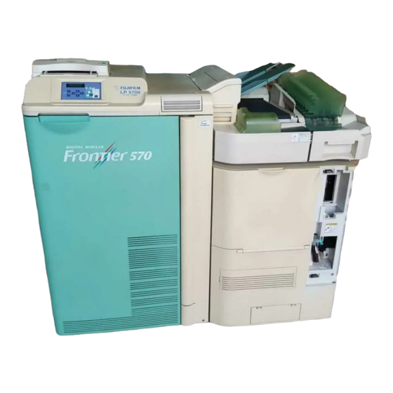
Distributed by minilablaser.com SERVICE MANUAL DIGITAL MINILAB FRONTIER 570 SCANNER/IMAGE PROCESSOR SP-3000 LASER PRINTER/PAPER PROCESSOR LP5700 Servicing and Electrical Circuit Diagram First Edition System Disk Ver.1.7 or later PP3-C1053E... - Page 2 This manual is a professional publication provided for qualified service personnel or persons fully trained in equipment service procedures. All other personnel and operators are restricted from servicing the SP-3000 and LP5700. When maintenance service is needed, be sure to contact qualified service personnel.
- Page 3 Distributed by minilablaser.com MENU TABLE MAINTENANCE AND INSPECTION MESSAGES AND ACTIONS SOFTWARE INSTALLATION MAINTENANCE MENU OPERATION SECTION FILM CARRIER SECTION SCANNER SECTION SCANNER ELECTRICAL SECTION PAPER SUPPLY SECTION PAPER FEED SECTION EXPOSURE SECTION DISTRIBUTION/PRINTER EXIT SECTION PROCESSOR SECTION PROCESSING SOLUTION CIRCULATION SYSTEM PROCESSING SOLUTION REPLENISHMENT SYSTEM DRYER SECTION PRINT EXIT SECTION/SORTER...
-
Page 4: Table Of Contents
Distributed by minilablaser.com CONTENTS MENU TABLE ........................... 1-1 Setup and Maintenance Menu Table................... 1-2 Printer/Processor Operation Panel Menu Table..............1-6 1.2.1 Menu Table ....................... 1-6 1.2.2 0 [MENU] Item......................1-7 1.2.3 1 [STARTUP CHK.] Item ................... 1-8 1.2.4 2 [END CHK.] Item ....................1-10 1.2.5 3 [LANGUAGE] Item .................... - Page 5 Distributed by minilablaser.com 2.3.29 Processor Drive Chain Lubrication................2-21 2.3.30 Dryer Mesh Belt Inspection ..................2-21 MESSAGES AND ACTIONS ....................3-1 Error Indication Outline......................3-2 3.1.1 Message Number ...................... 3-2 3.1.2 Message Icon ......................3-2 3.1.3 X-#### Actions ......................3-2 Messages and Actions ......................
- Page 6 Distributed by minilablaser.com 5.2.9 Installation Information Reference (0126) ............... 5-13 5.2.10 Accumulated Production Information (0127) ............5-13 5.2.11 Installation Information Setup (0140) ..............5-15 5.2.12 Clear Error Log (0141) .................... 5-16 5.2.13 Shipping Information Reference (0142) ..............5-16 Print Condition Setup and Check (02) ................5-17 5.3.1 Paper Condition Setup (0200).................
- Page 7 Distributed by minilablaser.com 5.5.11 MFC10AY Focus Offset Adjustment (0442) ............5-80 5.5.12 NC100AY Sensor Calibration Information (0443) ........... 5-81 5.5.13 NC100AY Installation Information Display (0444) ........... 5-83 5.5.14 MFC10AY Installation Information Display (0445) ..........5-83 5.5.15 NC100AY Installation Information Setup (0446) ............. 5-84 5.5.16 MFC10AY Installation Information Setup (0447).............
- Page 8 Distributed by minilablaser.com 5.7.4 Processor Temperature Calibration (0623) ............5-125 5.7.5 Processor Input Check (0624)................5-127 5.7.6 Processor Operating Condition Setup (0625) ............5-128 5.7.7 Processing Temperature Setting (0640) ............... 5-129 5.7.8 Processor I/O Check (0642).................. 5-130 5.7.9 Processor Operation Data Display (0643)............. 5-131 5.7.10 PS Liquid Concentration Management (0644) ............
- Page 9 Distributed by minilablaser.com 7.1.8 LBF23 Circuit Board Replacement................7-13 7.1.9 IX240 Feed Roller Replacement ................7-14 7.1.10 IX240 Dust Removal Roller Replacement............... 7-15 7.1.11 Dummy Head Replacement ..................7-17 7.1.12 Magnetic Reading Head (D124) Replacement............7-17 7.1.13 Magnetic Writing Head (MG101) Replacement............7-18 7.1.14 Pressure Cover Hinge Replacement...............
- Page 10 Distributed by minilablaser.com 7.3.10 Supply Motor Home Position Sensor (D122)/SSD23 Circuit Board Replacement .. 7-63 7.3.11 IPI Sensor (D121)/SSA23 Circuit Board Replacement ........... 7-63 7.3.12 Cartridge Holder Assembly Replacement ............... 7-65 7.3.13 Spool Gear Replacement ..................7-66 7.3.14 Cartridge Release Lever Assembly Replacement........... 7-66 7.3.15 Supply Motor (M102) Replacement.................
- Page 11 Distributed by minilablaser.com 8.1.7 Light Source Section Exhaust Fan (F311) Replacement .......... 8-8 Scanner Section ........................8-9 8.2.1 Scanner Section Rear Cover Removal/Reinstallation..........8-9 8.2.2 Scanner Section Upper Cover Removal/Reinstallation..........8-9 8.2.3 Scanner Section Front Cover Removal/Reinstallation ..........8-9 8.2.4 Scanner Section Exhaust Fan (F211) Replacement ..........
- Page 12 Distributed by minilablaser.com 10. PAPER SUPPLY SECTION ....................10-1 Parts Location........................10-2 10.1 Paper Magazine ........................ 10-3 10.1.1 Paper Supply Section Assembly Replacement ............10-3 10.1.2 Magazine Roller Release Arm Replacement ............10-3 10.1.3 Drive Pulley Replacement ..................10-4 10.2 Upper Paper Magazine Table...................
- Page 13 Distributed by minilablaser.com 11.1.15 Lower Cutter Unit Removal/Reinstallation............. 11-16 11.1.16 Feed Guide Plate Replacement ................11-17 11.1.17 Exit Nip Roller/Lower Magazine Entrance Nip Roller Replacement...... 11-17 11.1.18 Lower Cutter Feed Roller Replacement ..............11-18 11.1.19 Upper Cutter Feed Roller Replacement ..............11-19 11.1.20 Emulsion Surface Side Upper Cutter Exit Guide Plate Removal/Reinstallation..
- Page 14 Distributed by minilablaser.com 11.3.17 Registration Section Nip Roller 1 Replacement ............ 11-54 11.3.18 Feed Roller 1 Drive Gear Replacement ..............11-55 12. EXPOSURE SECTION ......................12-1 Parts Location........................12-2 12.1 LDD Circuit Board/AOM Driver Section ................12-3 12.1.1 Printer Top Cover Removal/Reinstallation .............. 12-3 12.1.2 Thermohygrometer (HS760) Replacement .............
- Page 15 Distributed by minilablaser.com 13.1.8 Nip Roller (M655 Side) Replacement..............13-13 13.1.9 Nip Release Home Position Sensor 3 (D656) Replacement......... 13-15 13.1.10 Nip Release Timing Belt (M656 Side) Replacement ..........13-15 13.1.11 Nip Release Motor 3 (M656) Replacement ............13-16 13.1.12 Nip Roller Replacement ..................13-16 13.1.13 Drive Gear Replacement..................
- Page 16 Distributed by minilablaser.com 13.3.14 Emulsion Surface Guide Plate Removal/Reinstallation......... 13-53 13.3.15 Entrance Back Surface Guide Plate Removal/Reinstallation ........ 13-54 13.3.16 Exit Back Surface Guide Plate Removal/Reinstallation ........13-54 13.3.17 Exit Feed Roller/Guide Plate Replacement............13-55 14. PROCESSOR SECTION ..................... 14-1 Parts Location........................
- Page 17 Distributed by minilablaser.com 15.2.4 Solution Heater (H700 to H703) Replacement............15-9 15.2.5 P1/P2 Circulation Pump (PU700/PU701) Replacement........15-10 15.2.6 PS1 to PS4 Circulation Pump (PU702 to PU705) Replacement......15-11 15.2.7 Processing Solution Tank Exhaust Fan 1 (F704) Replacement......15-13 15.2.8 Processing Solution Tank Exhaust Fan 2 (F705) Replacement......15-13 15.2.9 Hose Connection....................
- Page 18 Distributed by minilablaser.com 17.1.3 Dryer Belt Unit Open/Close Detecting Interlock Switch (D762B) Replacement ..17-5 17.2 Dryer Rack Section......................17-6 17.2.1 Dryer Rack Removal/Reinstallation................. 17-6 17.2.2 Dryer Section Open/Close Detecting Interlock Switch (D762A) Replacement..17-8 17.2.3 Dryer Feed Roller Drive Belt Replacement ............. 17-9 17.2.4 Dryer Feed Roller Replacement................
- Page 19 Distributed by minilablaser.com 18.4 SU1400AY Sorter ......................18-34 18.4.1 SU1400AY Sorter Removal/Reinstallation ............18-34 18.4.2 Sorter Cover Removal/Reinstallation ..............18-34 18.4.3 SWA20 Circuit Board Replacement ..............18-35 18.4.4 Sorter Tray Stop Position Sensor (D810) Replacement........18-35 18.4.5 Sorter Drive Motor (M810) Replacement .............. 18-36 18.4.6 Sorter Full Sensor (D811) Replacement ...............
- Page 20 20.4.2 DC Voltage Check List ..................20-23 20.4.3 DC Power Supply Unit Fuses and LEDs ............... 20-24 20.4.4 Circuit Board Layout Diagrams ................20-26 20.5 Scanner (SP-3000) Wiring Diagrams ................20-29 20.5.1 Scanner Wiring Diagram ..................20-29 20.5.2 Auto Film Carrier NC100AY Wiring Diagram ............20-32 20.5.3 Multi-film Carrier MFC10AY Wiring Diagram............
- Page 21 Distributed by minilablaser.com 20.6.3 “POWER” LEDs on the Operation Panel............... 20-37 20.6.4 DC Power Supply System LED Indication............. 20-39 20.6.5 Circuit Board Layout Diagrams ................20-44 20.7 Printer/Processor Wiring Diagrams ................. 20-53 20.7.1 AC Power Supply Wiring Diagram ................ 20-53 20.7.2 PAC23 Circuit Board Wiring Diagram ..............
-
Page 22: Menu Table
Distributed by minilablaser.com 1. MENU TABLE Setup and Maintenance Menu Table............. 1-2 Printer/Processor Operation Panel Menu Table ........1-6 1.2.1 Menu Table....................... 1-6 1.2.2 0 [MENU] Item ......................1-7 1.2.3 1 [STARTUP CHK.] Item ..................1-8 1.2.4 2 [END CHK.] Item ....................1-10 1.2.5 3 [LANGUAGE] Item .................... -
Page 23: Setup And Maintenance Menu Table
Distributed by minilablaser.com 1.1 Setup and Maintenance Menu Table Password Laboratory Submenu Menu Operator Manager — 0000 7777 01 System Operation Setup 0100 Connection to Imaging Controller and Check 0101 Image Export Settings 0120 Production Information 0121 Timer Setup 0122 Data Backup 0123 Error Information Check 0124 DI Manager Administrative Setting 0125 Timer Waiting Time Setup... - Page 24 Distributed by minilablaser.com 1.1 Setup and Maintenance Menu Table Password Laboratory Submenu Menu Operator Manager — 0000 7777 03 Scanner Adjustment/ 0342 Carrier Inclination Display Maintenance 0343 CCD Data Display 0344 Lens Registration 0345 Optical Axis Adjustment 0346 Optical Magnification Calibration 0347 Focus Calibration 0348 Spectral Calibration 0349 LED Light Amount Adjustment...
- Page 25 Distributed by minilablaser.com 1.1 Setup and Maintenance Menu Table Password Laboratory Submenu Menu Operator Manager — 0000 7777 05 Printer Adjustment/ 0520 Paper Magazine Feeding Fine Adjustment Maintenance 0522 G Laser (SHG) Optimal Temperature Setup 0523 Paper Feed 0524 Printer Temperature Display 0525 Printer Input Check 0527 Image Position and Tilt Fine Adjustment 0528 Printer Function Select...
- Page 26 Distributed by minilablaser.com 1.1 Setup and Maintenance Menu Table Password Laboratory Submenu Menu Operator Manager — 0000 7777 Processor Adjustment/ 0620 Pump Output Measurement/Setting Maintenance Auto Cleaning Output Measurement/ 0621 Setting 0622 Low Volume Processing Setup 0623 Processor Temperature Calibration 0624 Processor Input Check 0625 Processor Operating Condition Setup 0640 Processor Temperature Setting...
-
Page 27: Printer/Processor Operation Panel Menu Table
Distributed by minilablaser.com 1.2 Printer/Processor Operation Panel Menu Table 1.2.1 Menu Table Classification User Laboratory Main Menu Sub Menu Description Manager STARTUP CHK 11 PROC TEMP. 12 CALIBRATION 13 MEASURE DENS 14 CTRL STRIPS END CHK. 21 STARTUP TME LANGUAGE 31 SET LANG. -
Page 28: Menu] Item
Distributed by minilablaser.com 1.2 Printer/Processor Operation Panel Menu Table 1.2.2 0 [MENU] Item MENU MENU MENU MENU MENU ENTER $ ✻ STANDBY 0 [MENU] 1 [STARTUP CHK] 1 STARTUP CHK. 1 PROC. TEMP. (See Subsection 1.2.3) (See Subsection 1.2.3) 0 [MENU] 2 [END CHK] 2 END CHK. -
Page 29: Startup Chk.] Item
Distributed by minilablaser.com 1.2 Printer/Processor Operation Panel Menu Table 1.2.3 1 [STARTUP CHK.] Item 0 [MENU] 1 STARTUP CHK. ENTER 1 [STARTUP CHK.] 11 <PROC. TEMP.> 1 PROC. TEMP. 30.5 11 <PROC. TEMP.> 30.5 11 <PROC. TEMP.> 30.5 11 <PROC. TEMP.> 30.5 11 <PROC. - Page 30 Distributed by minilablaser.com 1.2 Printer/Processor Operation Panel Menu Table 1 [STARTUP CHK.] 12 <CALIBRATION> 12 <CALIBRATION> 2 CALIBRATION START ENTER ENTER 12 <CALIBRATION> PRINTING 1 [STARTUP CHK.] 13 <MEASURE DENS> 13 <MEASURE DENS> 3 MEASURE DENS START MEASURING ENTER ENTER #Ixxxx ENTER MEASURE...
-
Page 31: End Chk.] Item
Distributed by minilablaser.com 1.2 Printer/Processor Operation Panel Menu Table 1.2.4 2 [END CHK.] Item 0 [MENU] 2 END CHK. ENTER 2 [END CHK.] 21 <CHK START> 21 <STARTUP TIME> ✻ 1 CHK START CHECKING 07/01/03 09:00 Only the date rises-descends. 21 <STARTUP TIME>... -
Page 32: Language] Item
Distributed by minilablaser.com 1.2 Printer/Processor Operation Panel Menu Table 1.2.5 3 [LANGUAGE] Item ENTER ENTER 0 [MENU] 3 [LANGUAGE] 31 <SET LANG.> 3 LANGUAGE 1 SET LANG. [English] ENTER 31 <SET LANG.> [Japanese] ENTER 3 [LANGUAGE] 32 <ORG. LANG No.> 2 ORG. -
Page 33: Check] Item
Distributed by minilablaser.com 1.2 Printer/Processor Operation Panel Menu Table 1.2.6 4 [CHECK] Item ENTER 0 [MENU] 4 [CHECK] 41 <PROC TEMP.> 4 CHECK 1 PROC TEMP. 43.0 41 <PROC TEMP.> 43.0 41 <PROC TEMP.> 45.0 41 <PROC TEMP.> 45.0 41 <PROC TEMP.> 31.6 1-12... -
Page 34: Select Func.] Item
Distributed by minilablaser.com 1.2 Printer/Processor Operation Panel Menu Table 1.2.7 5 [SELECT FUNC.] Item ENTER 5 [SELECT FUNC.] 51 <POWER OFF> 0 [MENU] 1 POWER OFF START 5 SELECT FUNC. ENTER #M0003 #POWER OFF [YES] ENTER POWER OFF ENTER #M0003 #POWER OFF [NO] 1-13... -
Page 35: Print Cond.] Item
Distributed by minilablaser.com 1.2 Printer/Processor Operation Panel Menu Table 1.2.8 6 [PRINT COND.] Item 0 [MENU] 6 PRINT COND. ENTER 6 [PRINT COND.] 61 <CALIBRATION> 1 CALIBRATION MAG. [UPPER] 61 <CALIBRATION> START 61 <CALIBRATION> ENTER MAG. [LOWER] 61 <CALIBRATION> ✻ PRINTING ENTER 61 <CALIBRATION>... -
Page 36: Special Print] Item
Distributed by minilablaser.com 1.2 Printer/Processor Operation Panel Menu Table 1.2.9 7 [SPECIAL PRINT] Item ENTER 0 [MENU] 7 [SPEC. PRINT] 71 <TEST PATTERN> 7 [SPEC. PRINT] 1 TEST PATTERN MAG. [UPPER] 71 <TEST PATTERN> MAG. [LOWER] 71 <TEST PATTERN> 71 <TEST PATTERN> TYPE GRID LENGTH [82.5] 71 <TEST PATTERN>... -
Page 37: System] Item
Distributed by minilablaser.com 1.2 Printer/Processor Operation Panel Menu Table 1.2.10 8 [SYSTEM] Item 0 [MENU] 8 [SYSTEM] (See 81 [PROC.TYPE].) 8 SYSTEM 1 PROC TYPE 8 [SYSTEM] (See 82 [PROC. METHOD].) 2 PROC METHOD 8 [SYSTEM] (See 83 [SORTER TYPE].) 3 SORTER TYPE 8 [SYSTEM] (See 84 [NIGHT ALARM].) - Page 38 Distributed by minilablaser.com 1.2 Printer/Processor Operation Panel Menu Table 82 [PROC. METHOD] ENTER 8 [SYSTEM] 82 <PROC. METHOD> 2 PROC.METHOD [FACTORY TEST] 82 <PROC. METHOD> [CP-49E] ENTER 83 [SORTER TYPE] ENTER 83 <SORTER TYPE> [NONE] ENTER ENTER 83 <SORTER TYPE> 8 [SYSTEM] [14 ORDER] 3 SORTER TYPE...
- Page 39 Distributed by minilablaser.com 1.2 Printer/Processor Operation Panel Menu Table 84 [NIGHT ALARM] ENTER ENTER 8 [SYSTEM] 84 <NIGHT ALARM> 4 NIGHT ALARM [OFF] ENTER 84 <NIGHT ALARM> [ON] 85 [SET AREA] ENTER ENTER 8 [SYSTEM] 85 <SET AREA> 5 SET AREA [Standard] ENTER 85 <SET AREA>...
-
Page 40: Installation] Item
Distributed by minilablaser.com 1.2 Printer/Processor Operation Panel Menu Table 1.2.11 9 [INSTALLATION] Item 0 [MENU] 9 INSTALLATION ENTER ENTER 9 [INSTALLATION] 91 <PSR AIR EXT.> 91 <PSR AIR EXT.> ✻ 1 PSR AIR EXT. START EXTRACTING AIR ENTER ENTER 9 [INSTALLATION] 92 <MIX REPL.>... -
Page 41: Maintenance And Inspection
Distributed by minilablaser.com 2. MAINTENANCE AND INSPECTION Maintenance Schedule ................2-2 Regular Maintenance and Inspection Table......... 2-3 Maintenance and Inspection Procedures..........2-4 2.3.1 Lens Cleaning ......................2-4 2.3.2 Mouse Cleaning ....................... 2-4 2.3.3 Auto Film Carrier Inspection .................. 2-4 2.3.4 Carrier Base Slider Rail Cleaning ................ -
Page 42: Maintenance Schedule
Distributed by minilablaser.com 2.1 Maintenance Schedule Every Day Schedule Every Every Every Every 3 Every 6 Every Pre-operational Post-operational Week Month Months Months Year Item Years Check Check Diffusion Box/LED Board Scanner Clean Cover Auto Film Carrier Scanner Clean NC100AY Feed Lanes Printer/ Process/ Control Strip... -
Page 43: Regular Maintenance And Inspection Table
Distributed by minilablaser.com 2.2 Regular Maintenance and Inspection Table Implementation Period (Every) 6 months year 2 Years 3 Years 5 Years Refer to Item Lens Clean Subsection 2.3.1 Mouse Clean Subsection 2.3.2 Auto Film Carrier Inspect Subsection 2.3.3 Floppy Disk Drive Inspect Subsection 2.3.7 CD-ROM Drive... -
Page 44: Maintenance And Inspection Procedures
Distributed by minilablaser.com 2.3 Maintenance and Inspection Procedures 2.3.1 Lens Cleaning 1. Wipe the lens surface clean using a lens cleaning cloth (TORAY TORAYSEE or equivalent). Use a lens cleaning fluid if it is available. Lens Z2498 2.3.2 Mouse Cleaning 1. -
Page 45: Carrier Base Slider Rail Cleaning
Distributed by minilablaser.com 2.3 Maintenance and Inspection Procedures 2.3.4 Carrier Base Slider Rail Cleaning 1. Wipe the carrier slider rails clean with a cloth Slider Rails moistened with alcohol solution (mixture of an equal amount of alcohol and water). 2. Wipe the carrier base slider rails clean with a cloth moistened with alcohol solution (mixture of an equal amount of alcohol and water). -
Page 46: Floppy Disk Drive Inspection
Distributed by minilablaser.com 2.3 Maintenance and Inspection Procedures 2.3.7 Floppy Disk Drive Inspection 1. Prepare a formatted floppy disk. 2. Insert the floppy disk into the floppy disk drive. Formatted Floppy Disk Z2041 3. Proceed to Menu 0122 “Data Backup”. 4. -
Page 47: Cd-Rom Drive Inspection
Distributed by minilablaser.com 2.3 Maintenance and Inspection Procedures 11. Remove the floppy disk from the floppy disk drive. Z2042 2.3.8 CD-ROM Drive Inspection 1. Press the CD-ROM eject button. CD-ROM Eject Button • The CD-ROM tray is ejected. CD-ROM Tray Z2534 2. -
Page 48: Printing Function Inspection
Distributed by minilablaser.com 2.3 Maintenance and Inspection Procedures 2.3.9 Printing Function Inspection 1. Perform: • scanner correction • print condition upkeep printing 2. Set the paper magazine for the largest size print available at the lab. 3. Proceed to Menu 0541 “Test Pattern Printing”. 4. -
Page 49: Cutter Inspection
Distributed by minilablaser.com 2.3 Maintenance and Inspection Procedures 2.3.10 Cutter Inspection 1. Check the edges of prints. If they are rough, replace the unit with a new one (See Subsection for the upper cutter or for the lower 11.1.12 11.1.19 one). -
Page 50: Registration Section Feed Roller Cleaning
Distributed by minilablaser.com 2.3 Maintenance and Inspection Procedures 5. Disconnect the connector. Screws (2) 6. Remove the two screws and then the back printer head. Installation Installation is essentially in the reverse order of removal. Connector Printer Head NOTE: After installation, adjust the printer head clearance (See Subsection 11.2.21). -
Page 51: Nip Release Mechanism (Before Exposure) Inspection
Distributed by minilablaser.com 2.3 Maintenance and Inspection Procedures 2.3.14 Nip Release Mechanism (before exposure) Inspection 1. Remove the left cover (See Subsection 11.1.1) Nip Release Solenoids (4) 2. Check the four nip release solenoids for smooth operation by moving them with hand. 3. -
Page 52: Cam Follower (Rubber Bearing) Replacement
Distributed by minilablaser.com 2.3 Maintenance and Inspection Procedures 6. Set the nip rollers and wipe the feed rollers clean with a cloth moistened with water while turning the knob. Feed Rollers Knob L2935 7. Wipe the scanning rollers clean with a cloth Paper moistened with water while feeding a sheet of paper to turn them. -
Page 53: Pipe Slider Inspection
Distributed by minilablaser.com 2.3 Maintenance and Inspection Procedures 4. Remove the two E-rings. Cam Followers (2) 5. Lift the nip roller assembly slightly and remove the two cam followers. Installation Installation is essentially in the reverse order of removal. E-rings (2) L21155 2.3.17 Pipe Slider Inspection 1. -
Page 54: Processing Rack Helical Drive Gear Lubrication
Distributed by minilablaser.com 2.3 Maintenance and Inspection Procedures 2.3.19 Processing Rack Helical Drive Gear Lubrication 1. Remove the crossover racks. 2. Wipe grease off the helical drive gears fitted on each rack. 3. Apply recommended grease to the helical drive GREASE gears. -
Page 55: Circulation Pump Inspection
Distributed by minilablaser.com 2.3 Maintenance and Inspection Procedures 2.3.21 Circulation Pump Inspection 1. Remove the processor front cover (See Subsection 15.1.1) 2. Turn ON the main power supply and the built-in circuit breaker, then press the START switch to start up the system. 1) Go to the second page of Menu 0642 “Processor I/O Check”. -
Page 56: Processing Solution Level Sensor Cleaning
Distributed by minilablaser.com 2.3 Maintenance and Inspection Procedures 2.3.23 Processing Solution Level Sensor Cleaning 1. Remove the processor inner cover (See Subsection Screw 15.1.3) 2. Open the replenisher box door. 3. Remove the circulation filter tray. 4. Remove the screw and then the splash-prevention cover. -
Page 57: Replenisher Level Sensor Cleaning
Distributed by minilablaser.com 2.3 Maintenance and Inspection Procedures 2.3.24 Replenisher Level Sensor Cleaning 1. Remove the right cover (See Subsection 14.4.1) Screws (2) 2. Remove the two screws and pull the replenisher tanks out. Replenisher Tanks L21131 3. Remove the two screws and then the level sensor. P1R Replenisher level Sensor Screws (2) P2RA... -
Page 58: Ps4 Solution Concentration Sensor Cleaning
Distributed by minilablaser.com 2.3 Maintenance and Inspection Procedures 2.3.25 PS4 Solution Concentration Sensor Cleaning 1. Remove the processor inner cover PS4 Solution Concentration Sensor (See Subsection 15.1.3) PS4 Solution Concentration Sensor 2. Loosen the screw and remove the water supply port inner cover. -
Page 59: Psr Level Sensor Inspection
Distributed by minilablaser.com 2.3 Maintenance and Inspection Procedures 4. Put the flashlight from above as shown. Flashlight 5. Look through the slits (peep holes) in the right cover and remove the waste solution tank cap. Connector Slits (Peep Holes) Tank Cap L21191 6. -
Page 60: Solution Hose And Clamp Inspection
Distributed by minilablaser.com 2.3 Maintenance and Inspection Procedures 3. The PSR level sensor is normal if its level matches the screen display. PSR Lower Level Sensor 4. Reinstall the right cover. PSR Upper Level Sensor L21151 2.3.28 Solution Hose and Clamp Inspection 1. -
Page 61: Processor Drive Chain Lubrication
Distributed by minilablaser.com 2.3 Maintenance and Inspection Procedures 2.3.29 Processor Drive Chain Lubrication 1. Remove all crossover racks. Chain 2. Wipe grease off the drive chain and sprockets. GREASE 3. Apply a sufficient amount of recommended grease to the drive chain. Recommended Grease: Minilab Grease (P/N: 891G02003) 4. -
Page 62: Messages And Actions
Distributed by minilablaser.com 3. MESSAGES AND ACTIONS Error Indication Outline................3-2 3.1.1 Message Number..................... 3-2 3.1.2 Message Icon ......................3-2 3.1.3 X-#### Actions......................3-2 Messages and Actions ................3-3 Trouble Shooting ................3-163 3.3.1 Film Carrier ......................3-163 3.3.2 CTB23 Circuit Board ................... 3-164 3.3.3 CTB23 Circuit Board +24V System .............. -
Page 63: Error Indication Outline
Distributed by minilablaser.com Error Indication Outline 3.1.1 Message Number The messages are identified by the following four codes. Symbol Error Trouble (Error requires action of the service representative.) Mismatching of condition (Error can be corrected by the operator.) Information Software trouble 3.1.2 Message Icon Icon Error... -
Page 64: Messages And Actions
Distributed by minilablaser.com Messages and Actions Message Factor Actions W-1406 #### not installed or paper end Magazine is not installed. processing in progress. (Causes of the error message) 1. Magazine not installed. 1. Install magazine. Install the magazine, and then start 2. - Page 65 Distributed by minilablaser.com 3.2 Messages and Actions Message Factor Actions W-1422 A communication error occurred “No response” is received from between the main control section and printer at the start-up of the post- printer processor. operational check. (Causes of the error message) 1.
- Page 66 Distributed by minilablaser.com 3.2 Messages and Actions Message Factor Actions I-1455 Magnetic data registered on film Magnetic information contents error. failure. (Causes of the error message) 1. Dust or dirt collected on the 1. Clean the magnetic head and scan Continue the process ignoring the magnetic head.
- Page 67 Distributed by minilablaser.com 3.2 Messages and Actions Message Factor Actions W-1492 Carrier not installed. Carrier is not installed. (Causes of the error message) Install carrier and press [OK]. 1. Carrier is not installed. 1. Install the carrier. 2. Faulty carrier I/O or electric system (See Subsection 3.3.1) W-1495 Select the correct magazine paper...
- Page 68 Distributed by minilablaser.com 3.2 Messages and Actions Message Factor Actions W-1512 The FD free space insufficient. Inserted FD is full. (Causes of the error message) Insert the correct floppy disk into the 1. Inserted floppy disk is full. 1. Insert a blank disk. FD drive.
- Page 69 Distributed by minilablaser.com 3.2 Messages and Actions Message Factor Actions W-1531 FDi device registration failed. Error in registering F-DIA logical output devices. (can be recovered) Check the network connections, and (Causes of the error message) then press the [Retry] button. 1.
- Page 70 Distributed by minilablaser.com 3.2 Messages and Actions Message Factor Actions W-1542 Couldn’t provide the service. Error caused by status change during normal printing. Check the network connections, and (Causes of the error message) then press the [Retry] button. 1. Poorly connected LAN cable 1.
- Page 71 Distributed by minilablaser.com 3.2 Messages and Actions Message Factor Actions E-1552 Could not start up the Red-eye/Soft/ Error has occurred when starting Red Cross plug-in. Eye/Cross software. (Causes of the error message) The Red-eye/Soft/Cross plug-in not 1. Faulty Frontier system software 1.
- Page 72 Distributed by minilablaser.com 3.2 Messages and Actions Message Factor Actions W-1575 Preparing of variety printing is not Pre-scanning is attempted while – completed yet. setting up a template. Couldn’t start scan. The film is fed out. W-1586 Couldn’t start scan, because the Pre-scanning is attempted while Wait a while and then reload the film.
- Page 73 Distributed by minilablaser.com 3.2 Messages and Actions Message Factor Actions E-1599 An error occurred. Red eye/Soft/Cross failed to start up. (Causes of the error message) Couldn’t continue the “Red-eye/Soft/ 1. The carrier or mask is removed 1. Restart Red eye/Soft/Cross plug- Cross”.
- Page 74 Distributed by minilablaser.com 3.2 Messages and Actions Message Factor Actions I-1732 Couldn’t change the film drive mode This message appears when the – to ####. selected film drive mode is invalid depending on the carrier type. “Semi” is used. I-1733 A film is inserted while [All] setting for A film is inserted.
- Page 75 Distributed by minilablaser.com 3.2 Messages and Actions Message Factor Actions E-1750 More frames than the specified This message appears when the Change number of frames or use frames are detected. system recognizes the strip film but piece film with specified number of cannot find the frame with the starting frames.
- Page 76 Distributed by minilablaser.com 3.2 Messages and Actions Message Factor Actions W-1753 ##### The pre-scanning cannot be performed. Eject film. (Causes of the error message) The film was inserted under the ##### condition that the waiting time for the leading frame position determination was 0 second.
- Page 77 Distributed by minilablaser.com 3.2 Messages and Actions Message Factor Actions W-1763 The printing operation cannot be The process in progress was forcibly Wait until one mounted print is canceled while the image is mounted. terminated while mounted or frame/ completed, or select [Print] or character printing was in progress.
- Page 78 Distributed by minilablaser.com 3.2 Messages and Actions Message Factor Actions E-1780 Could not detect the frame No. Starting frame number of the film Enter the frame number correctly, or Could not print with this film strip. strip was not detected in the 135 insert the proper film strip.
- Page 79 Distributed by minilablaser.com 3.2 Messages and Actions Message Factor Actions W-1795 The carrier that is appropriate to the This message appears when you Install the carrier correctly. reorder printing is not installed. select the reordering service while the MFC10AY is installed. Replace the carrier, and then select the service menu again.
- Page 80 Distributed by minilablaser.com 3.2 Messages and Actions Message Factor Actions W-1912 Carrier upper cover opened. Scanning was attempted while the upper cover was open. Close it and then start pre-scan. (Causes of the error message) 1. Open pressure cover 1. Close the pressure cover. 2.
- Page 81 Distributed by minilablaser.com 3.2 Messages and Actions Message Factor Actions E-1999 Error table items (####) are incorrect. Incorrect values are written in the Sub-system: #### error table file. (####) (Causes of the error message) Error No.: #### 1. Faulty system software 1.
- Page 82 As printer setup and maintenance is During the printer/processor in progress, the printer maintenance maintenance, the maintenance mode not started. has been activated on the SP-3000. (Causes of the error message) 1. While the printer/processor 1. After quitting the maintenance maintenance mode is activated on...
- Page 83 Distributed by minilablaser.com 3.2 Messages and Actions Message Factor Actions I-2305 The data in the printer backup – – memory was updated. This message does not mean abnormality when the software version is updated. For other than the version up, consult your technical representative.
- Page 84 Distributed by minilablaser.com 3.2 Messages and Actions Message Factor Actions W-2314 Updating backup memory in printer File acquisition has failed while failed. connecting to the scanner. Check parameter file. (Causes of the error message) 1. Insufficient number of printer/ 1. Load the machine parameters processor parameter files are from the FD.
- Page 85 Distributed by minilablaser.com 3.2 Messages and Actions Message Factor Actions E-2350 Printer rear upper exhaust fan(F600/ Fan rotation cannot be detected. F601/F602/F603) abnormal. (Causes of the error message) Shut down scanner with emergency 1. Poorly connected or broken 1. Connect the harness correctly, or stop button and restart it.
- Page 86 Distributed by minilablaser.com 3.2 Messages and Actions Message Factor Actions W-2402 Paper jam occurred in lower supply D629 sensor does not detect the section(2). leading end of paper within a Check it. %NUM% sheets remain. specified time after the paper has Press [Help] button to see error help been drawn from the lower paper (or manual).
- Page 87 Distributed by minilablaser.com 3.2 Messages and Actions Message Factor Actions W-2404 Paper jam occurred in back printing/ D633 sensor does not detect the feed section (4). leading end of paper within a Check it. ### sheets remain. specified time after D631 or D632 Press [Help] button to see error help sensor detects the leading end of (or manual).
- Page 88 Distributed by minilablaser.com 3.2 Messages and Actions Message Factor Actions W-2406 Paper jam occurred between D664 or D665 sensor does not detect exposure section and distribution the leading end of paper within a entrance section(6). specified time after D650 sensor Check it.
- Page 89 Distributed by minilablaser.com 3.2 Messages and Actions Message Factor Actions W-2411 Paper remains in printer. 1. System is started up after the Press [Help] button to see error help power is turned OFF while (or manual). Inspect it while referring processing paper.
- Page 90 Distributed by minilablaser.com 3.2 Messages and Actions Message Factor Actions W-2413 Lower cutter operation(M601/D603/ Home position or close sensor does D604) abnormal. not function during operation. When a paper jam occurs in the (Causes of the error message) printer section, this problem is solved 1.
- Page 91 Distributed by minilablaser.com 3.2 Messages and Actions Message Factor Actions W-2416 Initializing of nip in exposure section Exposure soft nip home position is (M651/D651) failed. not detected (Sensor did not function Open and close magazine door. If even if the soft nip motor is driven problems persist, consult your specified pulses).
- Page 92 Distributed by minilablaser.com 3.2 Messages and Actions Message Factor Actions W-2419 Initializing of distribution Distribution home position cannot be section(M661/D661) failed. detected. Open and close magazine door. If (Causes of the error message) problems persist, consult your 1. Poorly connected or broken 1.
- Page 93 Distributed by minilablaser.com 3.2 Messages and Actions Message Factor Actions W-2424 Magazine ID not registered. Unregistered magazine ID is set. Press [Help] button to see error help (Causes of the error message) (or manual). Set magazine while 1. Unregistered magazine 1.
- Page 94 Distributed by minilablaser.com 3.2 Messages and Actions Message Factor Actions W-2430 Magazine section door open. Magazine door is opened during Close magazine section door. printing. (Causes of the error message) 1. Magazine door is opened. 1. Close the magazine door. 2.
- Page 95 Distributed by minilablaser.com 3.2 Messages and Actions Message Factor Actions W-2440 Paper end detected in lower – – magazine. Install a new paper in magazine. W-2441 Specified magazine ID differs from Even though printing is attempted by the stored ID. specifying a magazine ID, the Install magazine with ID=###.
- Page 96 Distributed by minilablaser.com 3.2 Messages and Actions Message Factor Actions W-2446 Loading of paper in lower magazine The splice sensor does not change failed. after paper is fed specified length No paper or paper jam in magazine. from the magazine. Press [Help] button to see error help (Causes of the error message) (or manual).
- Page 97 Distributed by minilablaser.com 3.2 Messages and Actions Message Factor Actions W-2449 Initializing of lower cutter • Both the cutter open and close failed(M601,D603,D604). sensors detect their home position. Shut down scanner with emergency • Cutter error flag is detected. stop button and restart it. If problems •...
- Page 98 Distributed by minilablaser.com 3.2 Messages and Actions Message Factor Actions W-2454 Nip in distribution section(M662/ Nip release home position cannot be D662/M663/D663) malfunction. detected. Shut down scanner with emergency (Causes of the error message) stop button and restart it. If problems 1.
- Page 99 Distributed by minilablaser.com 3.2 Messages and Actions Message Factor Actions W-2457 Paper may be slipped from feed Paper cannot be fed due to its length rollers in magazine. too short because the splice sensor Remove paper from magazine and detects paper and the paper end set it correctly in a dark location.
- Page 100 Distributed by minilablaser.com 3.2 Messages and Actions Message Factor Actions W-2461 Paper is not Installed in lower Lower magazine paper end is magazine. detected during initialization. Install a paper in magazine. (Causes of the error message) 1. Paper is not installed in the 1.
- Page 101 Distributed by minilablaser.com 3.2 Messages and Actions Message Factor Actions E-2504 AOM driver cooling fan malfunction. AOM cooling fan malfunction Shut down scanner with emergency (Rotating sensor malfunction). stop button and restart it. If problems (Causes of the error message) persist, consult your technical 1.
- Page 102 Distributed by minilablaser.com 3.2 Messages and Actions Message Factor Actions E-2510 Abnormal G laser (G-SHG) Abnormal data read from EEPROM in information. the laser unit at start-up. The laser temperature control (Causes of the error message) stopped. 1. Poorly connected or broken 1.
- Page 103 Distributed by minilablaser.com 3.2 Messages and Actions Message Factor Actions E-2516 Abnormal G laser (G-SHG) 1. Laser temperature exceeds the temperature. range. The laser temperature control 2. Thermistor error is detected. stopped. (Causes of the error message) Shut down scanner with emergency 1.
- Page 104 Distributed by minilablaser.com 3.2 Messages and Actions Message Factor Actions E-2520 R laser (R-LD) current exceeded. LD current value limiter detection. Shut down scanner with emergency (Causes of the error message) stop button and restart it. If problems 1. Poorly connected or broken 1.
- Page 105 Distributed by minilablaser.com 3.2 Messages and Actions Message Factor Actions W-2528 B laser (B-LD) current exceeds the Laser deterioration was detected at specified range. the last post-operational check. Shut down scanner with emergency (Causes of the error message) stop button and restart it. If problems 1.
- Page 106 Distributed by minilablaser.com 3.2 Messages and Actions Message Factor Actions W-2537 The laser temperature control cannot After the initialization, the ambient be performed, because the ambient temperature has been outside the temperature is too low(high). specified range for more than the Adjust the ambient temp.
- Page 107 Distributed by minilablaser.com 3.2 Messages and Actions Message Factor Actions E-2547 Fuse in exposure section blown out. Blown fuse is detected. Shut down scanner with emergency (Causes of the error message) stop button and restart it. If problems 1. Blown fuse on the LDD23 circuit 1.
- Page 108 Distributed by minilablaser.com 3.2 Messages and Actions Message Factor Actions W-2556 Initializing is in progress, so density Density measurement cannot be measurement cannot be started. started because the densitometer After initialization, retry initialization is in progress. measurement. (Causes of the error message) 1.
- Page 109 Distributed by minilablaser.com 3.2 Messages and Actions Message Factor Actions W-2562 Detecting of leading end of the print The leading end of the print upkeep failed. chart cannot be detected during Insert the condition setup print into density measurement. the densitometer correctly, and (Causes of the error message) perform the measurement again.
- Page 110 Distributed by minilablaser.com 3.2 Messages and Actions Message Factor Actions W-2568 Ejecting of the print failed. Chart is not ejected from the Insert the condition setup print into densitometer. the densitometer correctly, and (Causes of the error message) perform the measurement again. 1.
- Page 111 Distributed by minilablaser.com 3.2 Messages and Actions Message Factor Actions W-2603 Paper remains in dryer exit unit. Paper remains in the high-speed Press [Help] button to see error help feeding section when the processor is (or manual). Remove paper while driven.
- Page 112 Distributed by minilablaser.com 3.2 Messages and Actions Message Factor Actions W-2609 The dryer unit (D762A) or the dryer Processing tank’s or accumulating cover (D762B) opened. section’s cover is opened during Processing cancelled. Paper may paper processing. remain. (Causes of the error message) Press [Help] button to see error help 1.
- Page 113 Distributed by minilablaser.com 3.2 Messages and Actions Message Factor Actions E-2618 Dryer section temperature not rising. Dryer section temperature does not The heaters (H760 to 767) turned off. rise more than 1 °C in a minute at Shut down scanner with emergency heat up.
- Page 114 Distributed by minilablaser.com 3.2 Messages and Actions Message Factor Actions E-2625 P2 safety thermostat (D701) Safety thermostat in the P2 activated. processing tank is activated. The heaters (H700 to H703) turned (Causes of the error message) off. 1. Abnormal heater system ...
- Page 115 Distributed by minilablaser.com 3.2 Messages and Actions Message Factor Actions W-2633 PS3 solution level (FS704) has fallen. Solution level in PS3 processing tank Temperature adjustment stopped. is lowered. Press [Help] button to see error help (Causes of the error message) (or manual).
- Page 116 Distributed by minilablaser.com 3.2 Messages and Actions Message Factor Actions W-2650 Waste solution tank nearly full. Internal waste solution sensor Collect the solution in the recovery detects “Solution exists”. tank in the W2 manner. (Causes of the error message) 1. Waste solution tank is full. 1.
- Page 117 Distributed by minilablaser.com 3.2 Messages and Actions Message Factor Actions E-2659 P2RB replenishment flow volume or Accumulated output amount of its solution level abnormal. solution to P2RB upper level sensor About 510 3R-size sheets can still be exceeds the specified value (777.0 printed without replenishment.
- Page 118 Distributed by minilablaser.com 3.2 Messages and Actions Message Factor Actions W-2668 SU2400AY alignment operation Abnormal print alignment (M814/D814) abnormal. (Causes of the error message) Shut down scanner with emergency 1. Poorly connected or broken sorter 1. Connect the cable correctly, or stop button and restart it.
- Page 119 Distributed by minilablaser.com 3.2 Messages and Actions Message Factor Actions W-2674 Replenisher cartridge empty. When the lower level sensor detected Insert a new replenisher cartridge. “no solution in all tanks” within the specified time after the valve was opened. (Causes of the error message) 1.
- Page 120 Distributed by minilablaser.com 3.2 Messages and Actions Message Factor Actions W-2680 Number of prints exceeds limit. Accumulated output amount of P1R Stop printing. replenisher exceeds the specified Press [Help] button to see error help range. (or manual). Mix replenisher while (Causes of the error message) 1.
- Page 121 Distributed by minilablaser.com 3.2 Messages and Actions Message Factor Actions W-2696 Switching operation in feed Abnormal operation of the feeding lane(S770/D776) abnormal. path switching guide is detected. Shut down scanner with emergency (Causes of the error message) stop button and restart it. If problems 1.
- Page 122 Distributed by minilablaser.com 3.2 Messages and Actions Message Factor Actions W-2753 Concentration of the PS4 tank Measurement result of solution processing solution is out of range. concentration is abnormal Throw away waste and 4L FRSS (Causes of the error message) water put PS4 tank with PS2 (No.4) 1.
- Page 123 Distributed by minilablaser.com 3.2 Messages and Actions Message Factor Actions I-2765 Initializing dryer. Initial dryer temperature control is in Please wait. progress. (Causes of the error message) 1. When the power is turned OFF 1. Wait until dryer initialization is and ON, dryer initialization is completed(maximum of 5 performed.
- Page 124 Distributed by minilablaser.com 3.2 Messages and Actions Message Factor Actions E-4207 The image processing is not Conversion executed without GPA operable. circuit board (Convertible number zero) Consult your technical (Causes of the error message) representative. 1. GPA23 circuit board in incorrect 1.
- Page 125 Distributed by minilablaser.com 3.2 Messages and Actions Message Factor Actions E-4225 An error occurred in the image Partition change failure (H/W or processing section. software abnormal) (Causes of the error message) Restart the system. 1. Software abnormal 1. Restart the system software. If the error occurs again, reinstall the If problems persist, consult your system software.
- Page 126 Distributed by minilablaser.com 3.2 Messages and Actions Message Factor Actions E-4243 A failure in the GPA circuit board was (Causes of the error message) detected. (SLOT: ####) 1. Poorly inserted GPA23 circuit 1. Insert the circuit board in the slot board securely.
- Page 127 Distributed by minilablaser.com 3.2 Messages and Actions Message Factor Actions E-4274 An error occurred in the image JPEG parameter abnormal (Script processing section. parameter) (Causes of the error message) Check the print is correctly done. 1. DIC setup (Quality Factor) 1.
- Page 128 Distributed by minilablaser.com 3.2 Messages and Actions Message Factor Actions W-4318 The film remains in the carrier. Film remains in NC100AY carrier Remove the film and then start the when intending to carry out scanner scanner correction. Couldn’t perform the scanner correction (pre-operational checks).
- Page 129 Distributed by minilablaser.com 3.2 Messages and Actions Message Factor Actions W-4328 Wrong combination of film mask and Incorrect combination of diffusion box Replace the mask or diffusion box. diffusion box. and mask Check combination of film mask and diffusion box. W-4330 The leading frame is not detected.
- Page 130 Distributed by minilablaser.com 3.2 Messages and Actions Message Factor Actions W-4346 Couldn’t read the bar code on the Barcode cannot be read or film. information delayed in one-way mode. Continue processing. (Causes of the error message) 1. Notched film or fogged film edge Proceed processing and check color, 2.
- Page 131 Distributed by minilablaser.com 3.2 Messages and Actions Message Factor Actions W-4354 An incorrect parameter in the CPZ Parameter of the scanner CPZ23 On Menu 0350 “Scanner Parameter circuit board. circuit board differs from one of the Check/Update”, perform the HDD. following.
- Page 132 Distributed by minilablaser.com 3.2 Messages and Actions Message Factor Actions I-4363 The scanner temperature control is Temperature control not completed. Wait until completion. not completed. Please wait. After the completion of temperature control, the selected menu will be automatically started. I-4364 The diffusion box is incorrect.
- Page 133 Distributed by minilablaser.com 3.2 Messages and Actions Message Factor Actions W-4375 An margin occurs in printing. White space occurs as a result of Try to crop the image. If the error computation using specified no white occurs again, restart the system Crop it not to create the margin.
- Page 134 Distributed by minilablaser.com 3.2 Messages and Actions Message Factor Actions W-4386 The sliding stage is not installed. Scanner correction demand is Set the mask table slider and then received when the mask table slider perform the scanner correction. Couldn’t perform the scanner is not set.
- Page 135 Distributed by minilablaser.com 3.2 Messages and Actions Message Factor Actions E-4395 A communication error occurred No response for the demand is Restart the system software. If the between the image processing obtained from the image creation same error occurs again, reinstall the section and image generating block.
- Page 136 Distributed by minilablaser.com 3.2 Messages and Actions Message Factor Actions E-4405 A time-out error occurred during the No response obtained when sending main control section command was command to main control unit issued. (Causes of the error message) 1. Poorly connected 1394 cable 1.
- Page 137 Distributed by minilablaser.com 3.2 Messages and Actions Message Factor Actions W-4413 Auto focus failed. No contrast at AF (Causes of the error message) Check if the film is set correctly. 1. Abnormal focus position 1. Perform the focus position adjustment value adjustment.
- Page 138 Distributed by minilablaser.com 3.2 Messages and Actions Message Factor Actions E-4419 The AD timing adjustment failed. DL level AD timing decision failure (Causes of the error message) Restart the system. If problems 1. Abnormal CCD23 circuit board 1. Reconnect, repair or replace the persist, consult your technical power supply harness harness.
- Page 139 Distributed by minilablaser.com 3.2 Messages and Actions Message Factor Actions W-4426 Detecting of the mask failed. At scanner correction, brightness correction or defect pixel creating Install the carrier and the mask (Causes of the error message) correctly. 1. Required 135 upper and lower 1.
- Page 140 Distributed by minilablaser.com 3.2 Messages and Actions Message Factor Actions E-4436 All channels for B-LED are Startup initializing disconnected. (Causes of the error message) 1. Faulty harness between CLE23 1. Reconnect, repair or replace the Consult your technical and LED23 circuit boards harness.
- Page 141 Distributed by minilablaser.com 3.2 Messages and Actions Message Factor Actions E-4446 An abnormal temperature was Startup initializing detected at the driver IC of the M202 (Causes of the error message) pulse motor. At startup: 1. Too high a room temperature(32˚C 1.
- Page 142 Distributed by minilablaser.com 3.2 Messages and Actions Message Factor Actions E-4458 Electrical failure occurred. Startup initializing (Causes of the error message) (CLE CB A+12V) 1. Faulty harness between power 1. Reconnect or replace the harness. supply unit and CLE23 circuit Restart the system.
- Page 143 Distributed by minilablaser.com 3.2 Messages and Actions Message Factor Actions E-4466 The diagnostics of the piezoelectric Broken Piezoelectric Actuator 1 or actuator failed. poorly connected connector at startup initialization It is possible to continue printing, but (Causes of the error message) the resolution may be deteriorated 1.
- Page 144 Distributed by minilablaser.com 3.2 Messages and Actions Message Factor Actions E-4471 The diagnostics of the piezoelectric Faulty high-pressure drive, monitor or actuator failed. displacement measuring circuit of Piezoelectric Actuator 2 at startup It is possible to continue printing, but initialization the resolution may be deteriorated (Causes of the error message) when you print with larger sizes than...
- Page 145 Distributed by minilablaser.com 3.2 Messages and Actions Message Factor Actions E-4476 The control of the CTB circuit board SKCTB-serial Transmission Driver 0 is abnormal. overrun error (Causes of the error message) Restart the system. If problems 1. Noise in electric line 1.
- Page 146 Distributed by minilablaser.com 3.2 Messages and Actions Message Factor Actions E-4481 The control of the CTB circuit board SKCTB-transmission 1 message is abnormal. sending error (Causes of the error message) Restart the system. If problems 1. Noise in electric line 1.
- Page 147 Distributed by minilablaser.com 3.2 Messages and Actions Message Factor Actions E-4488 The control of the CTB circuit board SKCTB-message delivery message is abnormal. sending error 2 (Causes of the error message) Restart the system. If problems 1. System software overload (foulty 1.
- Page 148 Distributed by minilablaser.com 3.2 Messages and Actions Message Factor Actions E-4497 The control of the CTB circuit board SKCTB-task creation error is abnormal. (Causes of the error message) 1. Abnormal software 1. Restart the system software. If the Restart the system. If problems error occurs again, reinstall the persist, consult your technical system software.
- Page 149 Distributed by minilablaser.com 3.2 Messages and Actions Message Factor Actions E-4505 The control of the CTB circuit board SKCTB-serial Transmission Driver 3 is abnormal. framing error (Causes of the error message) Restart the system. If problems 1. Noise in electric line 1.
- Page 150 Distributed by minilablaser.com 3.2 Messages and Actions Message Factor Actions E-4510 The control of the CTB circuit board SKCTB-serial Transmission Driver 3 is abnormal. sending overrun, framing and parity error Restart the system. If problems (Causes of the error message) persist, consult your technical 1.
- Page 151 Distributed by minilablaser.com 3.2 Messages and Actions Message Factor Actions E-4516 The control of the CTB circuit board SKCTB-serial Transmission Driver 4 is abnormal. framing error (Causes of the error message) Restart the system. If problems 1. Noise in electric line 1.
- Page 152 Distributed by minilablaser.com 3.2 Messages and Actions Message Factor Actions E-4521 The control of the CTB circuit board SKCTB-serial Transmission Driver 4 is abnormal. overrun, framing and parity error (Causes of the error message) Restart the system. If problems 1. Noise in electric line 1.
- Page 153 Distributed by minilablaser.com 3.2 Messages and Actions Message Factor Actions E-4528 An error occurred during accessing of SKCTB-I2C slave address + R/W the CTB circuit board external data sending error memory. (Causes of the error message) 1. Faulty system software 1.
- Page 154 Distributed by minilablaser.com 3.2 Messages and Actions Message Factor Actions E-4536 An error occurred during accessing of SKCTB-I2C sending OFF error the CTB circuit board external (Causes of the error message) memory. 1. Faulty system software 1. Restart the system software. If the error occurs again, reinstall the Restart the system.
- Page 155 Distributed by minilablaser.com 3.2 Messages and Actions Message Factor Actions E-4544 An error occurred during accessing of SKCTB-I2C lower-order address the CTB circuit board external sending failure memory. (Causes of the error message) 1. Faulty system software 1. Restart the system software. If the Restart the system.
- Page 156 Distributed by minilablaser.com 3.2 Messages and Actions Message Factor Actions E-4552 An error occurred during accessing of SKCTB-EEPROM R/W error the CTB circuit board external (Causes of the error message) memory. 1. Faulty system software 1. Restart the system software. If the error occurs again, reinstall the Restart the system.
- Page 157 Distributed by minilablaser.com 3.2 Messages and Actions Message Factor Actions E-4592 An error occurred during accessing of SKCTB-EEPROM writing abnormal the CTB circuit board external (Causes of the error message) memory. 1. Faulty system software 1. Restart the system software. If the error occurs again, reinstall the Restart the system.
- Page 158 Distributed by minilablaser.com 3.2 Messages and Actions Message Factor Actions E-4603 The control for the CLE circuit board SKCLE-message delivery message is abnormal. sending error (Causes of the error message) Restart the system. If problems 1. Faulty system software 1. Restart the system software. If the persist, consult your technical error occurs again, reinstall the representative.
- Page 159 Distributed by minilablaser.com 3.2 Messages and Actions Message Factor Actions E-4611 The control for the CLE circuit board SKCLE-message delivery is abnormal. semaphore return error (Causes of the error message) Restart the system. If problems 1. Faulty system software 1. Restart the system software. If the persist, consult your technical error occurs again, reinstall the representative.
- Page 160 Distributed by minilablaser.com 3.2 Messages and Actions Message Factor Actions E-4620 The control for the CLE circuit board SKCLE-task start error is abnormal. (Causes of the error message) 1. Faulty system software 1. Restart the system software. If the Restart the system. If problems error occurs again, reinstall the persist, consult your technical system software.
- Page 161 Distributed by minilablaser.com 3.2 Messages and Actions Message Factor Actions E-4625 The control for the CLE circuit board SKCLE-serial Transmission Driver 3 is abnormal. overrun and parity error (Causes of the error message) Restart the system. If problems 1. Noise in electric line 1.
- Page 162 Distributed by minilablaser.com 3.2 Messages and Actions Message Factor Actions E-4630 The control for the CLE circuit board SKCLE-transmission 2 message is abnormal. receiving error (Causes of the error message) Restart the system. If problems 1. Noise in electric line 1.
- Page 163 Distributed by minilablaser.com 3.2 Messages and Actions Message Factor Actions E-4637 An error occurred during accessing of SKCLE-I2C higher-order address the CLE circuit board external sending failure memory. (Causes of the error message) 1. Faulty system software 1. Restart the system software. If the Restart the system.
- Page 164 Distributed by minilablaser.com 3.2 Messages and Actions Message Factor Actions E-4645 An error occurred during accessing of SKCLE-I2C slave address + R/W the CLE circuit board external data sending error memory. (Causes of the error message) 1. Faulty system software 1.
- Page 165 Distributed by minilablaser.com 3.2 Messages and Actions Message Factor Actions E-4653 An error occurred during accessing of SKCLE-I2C slave address + R/W the CLE circuit board external data sending failure 2 memory. (Causes of the error message) 1. Faulty system software 1.
- Page 166 Distributed by minilablaser.com 3.2 Messages and Actions Message Factor Actions E-4662 The control for the CLE circuit board SKCLE-temperature control task is abnormal. receiving error (Causes of the error message) Restart the system. If problems 1. System software overload 1. Restart the system software. If the persist, consult your technical (faulty software) error occurs again, reinstall the...
- Page 167 Distributed by minilablaser.com 3.2 Messages and Actions Message Factor Actions E-4672 The control for the CPZ circuit board SKCPZ-message delivery memory is abnormal. pool obtaining error 0 (Causes of the error message) Restart the system. If problems 1. Faulty system software 1.
- Page 168 Distributed by minilablaser.com 3.2 Messages and Actions Message Factor Actions E-4681 The control for the CPZ circuit board SKCPZ-mail box creation error is abnormal. (Causes of the error message) 1. System software overload (faulty 1. Restart the system software. If the Restart the system.
- Page 169 Distributed by minilablaser.com 3.2 Messages and Actions Message Factor Actions E-4689 The control for the CPZ circuit board SKCPZ-serial Transmission Driver 3 is abnormal. parity and framing error (Causes of the error message) Restart the system. If problems 1. Noise in electric line 1.
- Page 170 Distributed by minilablaser.com 3.2 Messages and Actions Message Factor Actions E-4694 The control for the CPZ circuit board SKCPZ-serial Transmission Driver 3 is abnormal. sending timeout (Causes of the error message) Restart the system. If problems 1. Noise in electric line 1.
- Page 171 Distributed by minilablaser.com 3.2 Messages and Actions Message Factor Actions E-4700 An error occurred during accessing of SKCPZ-I2C slave address + R/W the CPZ circuit board external data sending error memory. (Causes of the error message) 1. Faulty system software 1.
- Page 172 Distributed by minilablaser.com 3.2 Messages and Actions Message Factor Actions E-4708 An error occurred during accessing of SKCPZ-I2C sending OFF error the CPZ circuit board external (Causes of the error message) memory. 1. Faulty system software 1. Restart the system software. If the error occurs again, reinstall the Restart the system.
- Page 173 Distributed by minilablaser.com 3.2 Messages and Actions Message Factor Actions E-4716 An error occurred during accessing of SKCPZ-I2C lower-order address the CPZ circuit board external sending failure memory. (Causes of the error message) 1. Faulty system software 1. Restart the system software. If the Restart the system.
- Page 174 Distributed by minilablaser.com 3.2 Messages and Actions Message Factor Actions E-4724 An error occurred during accessing of SKCPZ-EEPROM R/W error the CPZ circuit board external (Causes of the error message) memory. 1. Faulty system software 1. Restart the system software. If the error occurs again, reinstall the Restart the system.
- Page 175 Distributed by minilablaser.com 3.2 Messages and Actions Message Factor Actions E-4732 An error occurred during accessing of SKCPZ-EEPROM writing abnormal the CPZ circuit board external (Causes of the error message) memory. 1. Faulty system software 1. Restart the system software. If the error occurs again, reinstall the Restart the system.
- Page 176 Distributed by minilablaser.com 3.2 Messages and Actions Message Factor Actions E-4738 An abnormality occurred during SKCPZ-piezoelectric actuator initializing of the piezoelectric warming-up position 6 error actuator. (Causes of the error message) 1. Outside noise, such as cell phone 1. Keep the noise source far away. It is possible to continue printing, but transmissions, etc.
- Page 177 Distributed by minilablaser.com 3.2 Messages and Actions Message Factor Actions W-4745 Setting of the dark correction table At the time of scanning correction or failed. auto darkness correction (Causes of the error message) Restart the system. If problems 1. Faulty GIA23 circuit board 1.
- Page 178 Distributed by minilablaser.com 3.2 Messages and Actions Message Factor Actions E-4754 The voltage adjustment for the OFD2 Condition met error judgment at the failed. time of OFD2 adjustment. (Causes of the error message) Restart the system. If problems 1. Faulty CCD unit 1.
- Page 179 Distributed by minilablaser.com 3.2 Messages and Actions Message Factor Actions E-4761 Electrical failure occurred. (Causes of the error message) 1. Poorly connected CN2 to CCD 1. Reconnect the connector. (CCD CB -12V) circuit board 2. Poorly connected JCD1 connector 2. Reconnect the connector. Restart the system.
- Page 180 Distributed by minilablaser.com 3.2 Messages and Actions Message Factor Actions W-4805 The optical magnification calibration Optical magnification calibration was Perform the optical magnification is not performed yet. not performed at the time of calibration. executing focus calibration. Perform it. W-4806 The focus calibration is not performed Focus calibration was not performed Perform the focus calibration.
- Page 181 Distributed by minilablaser.com 3.2 Messages and Actions Message Factor Actions I-4816 Cancel the Measurement? Spectral calibration was canceled. Click [OK] to cancel. Please wait. I-4817 Performing the scanner correction. At the time of scanner correction Wait until correction is completed. execution Please wait.
- Page 182 Distributed by minilablaser.com 3.2 Messages and Actions Message Factor Actions I-4831 Detecting of the gray pixels is Detecting gray pixels is completed. Click [OK]. completed. W-4832 Carrier is not installed correctly. Carrier differs from the one installed when executing. Check the carrier. (Causes of the error message) 1.
- Page 183 Distributed by minilablaser.com 3.2 Messages and Actions Message Factor Actions W-4844 Couldn’t find the circuit board No circuit board parameter file Restart the system software. If the parameter file. error occurs again, reinstall the system software (NOTE1) W-4845 The optical magnification calibration Optical magnification calibration failed.
- Page 184 Distributed by minilablaser.com 3.2 Messages and Actions Message Factor Actions I-4856 Select the correct mask type for the NC100AY carrier 135F or 135H mask Select either one. bright correction table to be created. selection for brightness correction table creation Set the 135F mask or 135H mask. W-4857 Carrier is not installed.
- Page 185 Distributed by minilablaser.com 3.2 Messages and Actions Message Factor Actions W-4869 Carrier is not installed correctly. Abnormal NC100AY carrier operation (Causes of the error message) Install the carrier. 1. Carrier error such as film 1. Set the carrier to normal condition. remaining, carrier installed with pressure cover open, etc.
- Page 186 Distributed by minilablaser.com 3.2 Messages and Actions Message Factor Actions W-4904 The feeding lane of the carrier was Lane change operation detection switched. (Causes of the error message) 1. NC100AY feed lane changed 1. Change to the feed lane required. 2.
- Page 187 Distributed by minilablaser.com 3.2 Messages and Actions Message Factor Actions W-4920 Enter numerals only for the serial No. Entered characters except numerical of the circuit board. values in hardware Rev (Causes of the error message) 1. Entered characters except 1. Enter the serial number correctly. numerical value as circuit board serial number 2.
- Page 188 Distributed by minilablaser.com 3.2 Messages and Actions Message Factor Actions W-4934 An abnormality occurred during File I/O error writing to the monitor frame ratio (Causes of the error message) information file. 1. Faulty HDD 1. Replace the HDD. 2. Lack of HDD capacity 2.
- Page 189 Distributed by minilablaser.com 3.2 Messages and Actions Message Factor Actions E-5203 Communication error occurred Board definition command response between scanner and printer. timeout occurs three times (Retry over) consecatively (Causes of the error message) Consult your technical 1. Poorly connected 1394 cable 1.
- Page 190 Distributed by minilablaser.com 3.2 Messages and Actions Message Factor Actions W-6003 Incorrect feeding lane. Magnetic information reading diagnosis was executed with 135 Switch to the IX240 lane. feed lane. (Causes of the error message) 1. Feed lane differs from that 1.
- Page 191 Distributed by minilablaser.com 3.2 Messages and Actions Message Factor Actions E-6017 A conversion file is not found. No file (EzPcErr.tbl) Restart the system software. If the error occurs again, reinstall the Consult your technical system software. (NOTE1) representative. E-6019 Films with over 40 frames are not Too long a film was used.
- Page 192 Distributed by minilablaser.com 3.2 Messages and Actions Message Factor Actions E-6111 The hard disk drive in the main Abnormal HDD in main control unit is Replace the HDD. control unit is abnormal. detected. The diagnostics are required. W-7001 Carrier was removed. Carrier was removed with a film remaining in it during film feeding Remove film and then install the...
- Page 193 Distributed by minilablaser.com 3.2 Messages and Actions Message Factor Actions E-7010 Writing FlashROM data into carrier (Causes of the error message) failed. 1. Poorly connected plug-in 1. Remove and reinstall the carrier. connector Consult your technical 2. Faulty CYA23 circuit board 2.
- Page 194 Distributed by minilablaser.com 3.2 Messages and Actions Message Factor Actions W-7018 An IX240 film is inserted in the lane IX240 cartridge was inserted when other than IX240 lane. carrier was not in IX240 feed lane. (Causes of the error message) Remove the carrier and check the 1.
- Page 195 Distributed by minilablaser.com 3.2 Messages and Actions Message Factor Actions W-7028 Cartridge remains in carrier. IX240 cartridge existing carrier installation error Remove the carrier, and then take out (Causes of the error message) the cartridge. 1. Installed carrier or turned power 1.
- Page 196 Distributed by minilablaser.com 3.2 Messages and Actions Message Factor Actions W-7031 Feeding of film failed. ATP hole length is more than 8mm at feeding, or MTP cannot be found Remove carrier and then film. after feeding 9mm from ATP. (Causes of the error message) 1.
- Page 197 Distributed by minilablaser.com 3.2 Messages and Actions Message Factor Actions W-7035 Feeding of film failed. MTP center detected at returning feed differs by 5mm or more from one Remove carrier and then film. at pre-scanning. (Causes of the error message) 1.
- Page 198 Distributed by minilablaser.com 3.2 Messages and Actions Message Factor Actions W-7037 Feeding of film failed. ATP hole length is more than 8mm at time of return or MTP cannot be Remove carrier and then film. found after feeding 29mm from ATP. (Causes of the error message) 1.
- Page 199 Distributed by minilablaser.com 3.2 Messages and Actions Message Factor Actions W-7039 Feeding of film failed. MTP hole length was more than 8mm at time of feeding. Remove carrier and then film. (Causes of the error message) 1. Slipped or blocked film 1.
- Page 200 Distributed by minilablaser.com 3.2 Messages and Actions Message Factor Actions W-7042 Feeding of film failed. TAP cannot be detected. (Causes of the error message) Remove carrier and then film. 1. Slipped or blocked film 1. Clean the feed rollers or clear the cause of blocking.
- Page 201 Distributed by minilablaser.com 3.2 Messages and Actions Message Factor Actions W-7045 Unprocessed cartridge. Unprocessed cartridge (Causes of the error message) Not used. 1. Loaded unbroken IPI (unprocessd) 1. Remove the cartridge and reinstall cartridge the carrier. If it is a processed cartridge, fold IPI. 2.
- Page 202 Distributed by minilablaser.com 3.2 Messages and Actions Message Factor Actions W-7051 Film remains in IX240 feeding lane. Feed lane was changed during feeding IX240 film in NC100AY. Remove carrier and then film. (Causes of the error message) 1. Changed feed lane during 1.
- Page 203 Distributed by minilablaser.com 3.2 Messages and Actions Message Factor Actions W-7057 An error occurred in cartridge door. NC100AY IX240 door motor drive error Install the carrier again to use the (Causes of the error message) cartridge. 1. Damaged cartridge door 1.
- Page 204 Distributed by minilablaser.com 3.2 Messages and Actions Message Factor Actions W-7061 Magnetic head is stained. NC100AY IX240 magnetic information verify error May not read magnetic data. (Causes of the error message) 1. Dirty magnetic head (reading or 1. Clean the magnetic head. Remove carrier and then clean the writing) magnetic head.
- Page 205 Distributed by minilablaser.com 3.2 Messages and Actions Message Factor Actions E-7074 A communication error occurred Communication error to carrier between the GMB CB and carrier. (Causes of the error message) 1. Incorrectly installed carrier 1. Install the carrier correctly. Carrier is not installed correctly. 2.
- Page 206 Distributed by minilablaser.com 3.2 Messages and Actions Message Factor Actions E-7084 A power source failure (carrier Abnormal carrier +12V power supply section +12V) was detected. (Causes of the error message) 1. Incorrectly installed carrier 1. Install the carrier correctly. Carrier is not installed correctly. 2.
- Page 207 Distributed by minilablaser.com 3.2 Messages and Actions Message Factor Actions W-7098 Film remains in 135 feeding lane. Detected film by leading end sensor of NC100AY when exiting from Setup Remove carrier and then film. and Maintenance menu. (Causes of the error message) 1.
- Page 208 Distributed by minilablaser.com 3.2 Messages and Actions Message Factor Actions W-7106 Inserting of film failed. NC100AY 135 film loading reattempt error Remove carrier and then film. If (Causes of the error message) problems persist, clean the feeding 1. Blocked or hand-pulled film 1.
- Page 209 Distributed by minilablaser.com 3.2 Messages and Actions Message Factor Actions W-7110 Perforation rupture exists. Film damage (8.2mm or longer perforation length) was detected Frame position may not detected (upstream/right-feed/leading end correctly. near upstream perforation sensor). (Causes of the error message) Remove carrier and then film, and 1.
- Page 210 Distributed by minilablaser.com 3.2 Messages and Actions Message Factor Actions W-7113 Perforation rupture exists. Film damage (8.2mm or longer perforation length) was detected Frame position may not detected (upstream/right-feed/leading end at correctly. right side of downstream perforation sensor). Remove carrier and then film, and (Causes of the error message) mend the rupture.
- Page 211 Distributed by minilablaser.com 3.2 Messages and Actions Message Factor Actions W-7116 Perforation rupture exists. Film damage (8.2mm or longer perforation length) was detected Frame position may not detected (downstream/right-feed/leading end correctly. at right side of downstream perforation sensor). Remove carrier and then film, and (Causes of the error message) mend the rupture.
- Page 212 Distributed by minilablaser.com 3.2 Messages and Actions Message Factor Actions W-7119 Perforation rupture exists. Film damage (8.2mm or longer perforation length) was detected Frame position may not detected (downstream/left-feed/trailing end correctly. near upstream perforation sensors) (Causes of the error message) Remove carrier and then film, and 1.
- Page 213 Distributed by minilablaser.com 3.2 Messages and Actions Message Factor Actions W-7122 Feeding of film failed. Blocked perforation (8.2mm or longer between perforations) was detected Remove carrier and then film. (upstream/right-feed/leading end between upstream and downstream perforation sensors). (Causes of the error message) 1.
- Page 214 Distributed by minilablaser.com 3.2 Messages and Actions Message Factor Actions W-7125 Feeding of film failed. Blocked perforation (8.2mm or longer between perforations) was detected Remove carrier and then film. (upstream/left-feed/trailing end at left side of frame sensors). (Causes of the error message) 1.
- Page 215 Distributed by minilablaser.com 3.2 Messages and Actions Message Factor Actions W-7128 Feeding of film failed. Blocked perforation (8.2mm or longer between perforations) was detected Remove carrier and then film. (downstream/left-feed/trailing end at left side of frame sensors). (Causes of the error message) 1.
- Page 216 Distributed by minilablaser.com 3.2 Messages and Actions Message Factor Actions W-7131 Feeding of film failed. Blocked perforation (8.2mm or longer between perforations) was detected Remove carrier and then film. (downstream/left-feed/trailing end between upstream and downstream perforation sensors). (Causes of the error message) 1.
- Page 217 Distributed by minilablaser.com 3.2 Messages and Actions Message Factor Actions W-7134 Feeding of film failed. Perforation error range exceeds ±5mm when correcting feed at Remove carrier and then film. perforation decision (upstream/right- feed/trailing end near downstream perforation sensor). (Causes of the error message) 1.
- Page 218 Distributed by minilablaser.com 3.2 Messages and Actions Message Factor Actions W-7137 Feeding of film failed. Perforation error range exceeds ±5mm when correcting feed at Remove carrier and then film. perforation decision (upstream/left- feed/trailing end between frame and downstream perforation sensors). (Causes of the error message) 1.
- Page 219 Distributed by minilablaser.com 3.2 Messages and Actions Message Factor Actions W-7140 Feeding of film failed. Perforation error range exceeds ±5mm when correcting feed at Remove carrier and then film. perforation decision (downstream/ left-feed/trailing end between frame and upstream perforation sensors). (Causes of the error message) 1.
- Page 220 Distributed by minilablaser.com 3.2 Messages and Actions Message Factor Actions E-7172 Reading FlashROM data from carrier Abnormal carrier/FlashROM data failed. (Causes of the error message) 1. Poorly connected plug-in 1. Remove and reinstall the carrier. If Consult your technical connector the error occurs again, replace the representative.
- Page 221 Distributed by minilablaser.com 3.2 Messages and Actions Message Factor Actions W-7185 Film remains in 135 feeding lane. Detected remaining film on frame sensor of NC100AY carrier when Remove carrier and then film. exiting from maintenance menu (Causes of the error message) 1.
- Page 222 Distributed by minilablaser.com 3.2 Messages and Actions Message Factor Actions W-7211 The feeding lane position sensor (Causes of the error message) (D129) failed. 1. Foreign matter blocking 135/IX240 1. Remove the foreign matter. feed lane position sensor (D129/ The 135 feeding lane cannot be D130) used.
- Page 223 Distributed by minilablaser.com 3.2 Messages and Actions Message Factor Actions W-7219 A film remains at the right-hand side Downstream perforation sensor of the carrier. detects film before 135 upstream perforation sensor. Previous right- Remove the carrier, and then take out feed scanned film is left in the carrier the film.
-
Page 224: Trouble Shooting
Distributed by minilablaser.com Trouble Shooting 3.3.1 Film Carrier Abnormal Install other carrier. Is there any abnormality? Check if for dust on pins of plug-in Normal connector in scanner side, and remove it. Solved Check for connection error, breakage or dust collection, and repair connector, if necessary. -
Page 225: Ctb23 Circuit Board
Distributed by minilablaser.com 3.3 Trouble Shooting 3.3.2 CTB23 Circuit Board Come-off or Sensor abnormal. abnormal sound Use “I/O Check (0341)” to check sensor and motor. Motor driven? Motor not driven. Fuse F51 or F52 on CTB23 Check mechanical operation, circuit board burnt out? and repair or replace. -
Page 226: Ctb23 Circuit Board +24V System
Distributed by minilablaser.com 3.3 Trouble Shooting 3.3.3 CTB23 Circuit Board +24V System +24V Is 2 pin of CTB1 connector on CTB23 circuit board set to LOW (drive power-ON signal)? HIGH Replace CTB23 circuit board. Check harness between Malfunction CTB1 on CTB23 circuit board and PS5 on power supply unit. -
Page 227: Replenishment Cartridge Box Malfunction
Distributed by minilablaser.com 3.3 Trouble Shooting 3.3.4 Replenishment Cartridge Box Malfunction Open Replenisher box door open? Closed The harness between the replenisher box door open/close detecting interlock switch (D724) and PWR4 on the PWR23 circuit board is poorly connected or broken? Connect harness correctly, or repair or replace it. - Page 228 Distributed by minilablaser.com 3.3 Trouble Shooting Is the harness between the cartridge opening motor (M720) and PDB8 on the PDB23 circuit board is poorly connected or broken? Connect harness correctly, repair or replace it. Replace the cartridge opening Solved motor (M720). Solved? Not solved Replace the PDB23 circuit board.
-
Page 229: Processing Solution Temperature Abnormality
Distributed by minilablaser.com 3.3 Trouble Shooting 3.3.5 Processing Solution Temperature Abnormality Cool Touch heater surface. <Heater> Warm To “Temperature sensor”, “Processing solution circulation”, Is the harness between the heater and the “Safety thermostat”, “Heater cooling fan” PAC23 circuit board poorly connected or broken? H700 to PAC04 H701 to PAC05... - Page 230 Distributed by minilablaser.com 3.3 Trouble Shooting <Temperature sensor> Compare display values with measured Abnormal values on “Processor Temperature Calibration (0623)”. Normal Is the harness between the solution thermometer and the CTL23 circuit board is poorly connected or broken? TS700 to CTL7 TS701 to CTL7 PS1/2/3: TS702 to CTL7 PS4:...
- Page 231 Distributed by minilablaser.com 3.3 Trouble Shooting <Processing solution circulation> Remove circulation filter from sub-tank. Is solution surface inside sub-tank swirling? Is the harness between the circulation pump and the PDB23 circuit board poorly connected or broken? PU700 to PDB4 PU701 to PDB4 PS1: PU702 to PDB4 PS2: PU703 to PDB4 PS3: PU704 to PDB4...
- Page 232 Distributed by minilablaser.com 3.3 Trouble Shooting <Safety thermostat> Safety thermostat operated on “Processor Input Check (0624)”? Operating temperature:64°C Returned temperature:42°C Not operated Operating temperature: 64°C Returned temperature: 42°C PS1/2/3 Operating temperature: 80°C Returned temperature: 42°C Operated To “Heater cooling fan” Return at below 42°C? Is the harness between the safety thermometer and the PAC23 circuit board...
-
Page 233: Dryer Temperature Abnormality
Distributed by minilablaser.com 3.3 Trouble Shooting 3.3.6 Dryer Temperature Abnormality Removed Cover around dryer section removed? Not removed Install correctly. To “Dryer heater”, “Dryer temperature sensor”, “Dryer heater safety thermostat”, “Dryer fan”. <Dryer heater> Not risen Touch dryer section. Temperature risen? Risen The following protection devices are Tripped... - Page 234 Distributed by minilablaser.com 3.3 Trouble Shooting <Dryer temperature sensor> Not risen Dryer temperature risen on “Processor Temperature Calibration (0623)”? Risen Is the harness between the dryer thermometer (TS760) and CTL7 on the CTL23 circuit board poorly connected or broken ? To “Safety heater thermostat”, Connect harness correctly, “Dryer fan”...
- Page 235 Distributed by minilablaser.com 3.3 Trouble Shooting <Recovery of Safety Thermostat> 1. SU1400AY sorter: Remove the sorter. SU2400AY sorter: Move the sorter to its storage position. 2. Remove the two screws securing the dryer heater safety thermostat cover. Screws (2) LII913 3.
- Page 236 Distributed by minilablaser.com 3.3 Trouble Shooting <Dryer fan> Abnormal Dryer fan (F760) turned ON/OFF on “Processor I/O Check (0624)”? Normal Is the harness between the dryer fan (F760)and PDB9 on the PDB23 circuit board poorly connected or broken? Clean dryer air filter. Connect harness correctly, Open the dryer belt unit and make sure repair or replace it.
-
Page 237: Processing Solution Tank Level Lowering
Distributed by minilablaser.com 3.3 Trouble Shooting 3.3.7 Processing Solution Tank Level Lowering Remove circulation filter from sub-tank, and measure solution level from Lowering upper surface of sub-tank. less than 65mm: Normal more than 65mm: Lowering Normal Leakage Leakage in processing solution system? Normal To “Processing solution level sensor diagnostics”... -
Page 238: Replenishment Pump Diagnostics
Distributed by minilablaser.com 3.3 Trouble Shooting 3.3.8 Replenishment Pump Diagnostics Menu 0625 “Processor Operating Condition Setup” is set properly? Set correctly. Perform Menu 0620 “Replenisher Pump Abnormal Output Measurement/Setting. Normal?” Normal Hose clogged or bent in replenishment system? To “3.3.9 Rack Auto Cleaning Systen Diagnostics” Correct hose clogging or bending. -
Page 239: Rack Auto Cleaning System Diagnostics
Distributed by minilablaser.com 3.3 Trouble Shooting 3.3.9 Rack Auto Cleaning System Diagnostics Perform Menu 0621 “Auto Cleaning Normal Output Measurement/Setting”. Normal? Abnormal Is the harness between the auto washing pump (PU720) and PDB7 on the PDB23 circuit board poorly connected or broken? Connect harness correctly, repair or replace it. -
Page 240: P1R Stirring Valve/Replenishment Cartridge Washing Valve Diagnostics
Distributed by minilablaser.com 3.3 Trouble Shooting 3.3.10 P1R Stirring Valve/Replenishment Cartridge Washing Valve Diagnostics Operate valve on Menu 0642 “I/O Check”. Operating sound heard? Heard P1R cartridge washing valve: S728 P2RA cartridge washing valve: S729 P2RB cartridge washing valve: S730 P1R stirring valve: S731 Not heard... -
Page 241: Replenishment Level Sensor Diagnostics
Distributed by minilablaser.com 3.3 Trouble Shooting 3.3.11 Replenishment Level Sensor Diagnostics Abnormal Check level sensor and actual level on “Processor I/O Check (0642)”. Normal Is the harness between the level sensor and the JNE6 on the JNE23 circuit board is poorly connected or broken? P1R upper level sensor: FS720 P1R lower level sensor:... -
Page 242: Replenishment Cartridge Opening Malfunction
Distributed by minilablaser.com 3.3 Trouble Shooting 3.3.13 Replenishment Cartridge Opening Malfunction Remove replenisher cartridge. Solution remained in cartridge due to opening malfunction? Opening parts damaged or abnormal? Replace parts. To “3.3.12 Return Action after Replenishment System Error” Any object remained in opening nozzle hopper section? Remove object. -
Page 243: Restoration Of Backup For Refreshing
Distributed by minilablaser.com Restoration of Backup for Refreshing OS and application software files are compressed and stored in the HDD. They can be restored by performing this operation. 1. Shut down the system by performing post- operational check. 2. Insert the backup FD for refreshing (HDD Backup Tool) into the floppy disk drive. - Page 244 Distributed by minilablaser.com 3.4 Restoration of Backup for Refreshing 5. Remove the FD. Z2042 6. Press the power switch of the main control unit to shut down the scanner. 7. Start up the main control unit using the Shift key. 8.
-
Page 245: Os Recovery And Backup For Refreshing
Distributed by minilablaser.com OS Recovery and Backup for Refreshing 3.5.1 OS Recovery If the machine stops during starting up or the system freezes when changing the screen, although “Refreshing Backup Restoration” (see Section 3.4) is performed, reinstallation of “OS Windows 2000” may clear that problem. - Page 246 Distributed by minilablaser.com 3.5 OS Recovery and Backup for Refreshing 2. Press the START switch. START Switch Z2040 • The boot change screen appears. EZ201 PC Boot Device Change FD V1.06 - - - - - - - - - - - - - - - - - - - - - - - - - - - - - - - - - - - - - - 3.
- Page 247 Distributed by minilablaser.com 3.5 OS Recovery and Backup for Refreshing 5. Insert “Recovery CD 1” into the CD-ROM drive. Recovery CD 1 Z2043 6. Press the reset switch of the main control unit. Reset Switch Z2532 ● OS Recovery Procedure •...
- Page 248 Distributed by minilablaser.com 3.5 OS Recovery and Backup for Refreshing 3. Replace “Recovery CD 1” with “Recovery CD 2”. Recovery CD 2 Z2043-1 • The completion message appears. 4. Remove “Recovery CD 2” from the CD-ROM drive. 5. Insert the “Boot Device Change FD” into the floppy disk drive.
- Page 249 Distributed by minilablaser.com 3.5 OS Recovery and Backup for Refreshing • The restarting up screen appears. *** COMPLETE *** DATA WRITE to CMOS ************************************************** ****** Cautions. Very important ! ****** ****** You have to power-down and reset ****** * You must reset your computer before the new setting will take effect. * ************************************************** 2.
-
Page 250: Device Driver Installation
2. Turn the power switch ON to start up the Printer/ Processor and then to STANDBY. 3. Press the START switch of the Scanner. START Switch Z2040 4. Immediately after the SP-3000 starts up, insert Recovery CD 1 the driver disk into the CD-ROM drive. Z2043 3-189... - Page 251 Distributed by minilablaser.com 3.5 OS Recovery and Backup for Refreshing • The "Found New Hardware Wizard" screen appears. NOTE: The "Device Driver Disk [D-01]" dialog box may appear over the "Found New Hardware Wizard" screen. 5. Click the [Cancel] button of the "Found New Hardware Wizard"...
- Page 252 Distributed by minilablaser.com 3.5 OS Recovery and Backup for Refreshing • The "Found New Hardware Wizard" screen appears. NOTE: Proceed to Step 15 after the GIE23 circuit board of the scanner has been replaced. 10. Click the [Next >] button. 11.
- Page 253 Distributed by minilablaser.com 3.5 OS Recovery and Backup for Refreshing 13. Click the [Next >] button. NOTE: Proceed to Step 19 after the GIE23 circuit board of the printer/processor has been replaced. 14. Click the [Finish] button. • The "Found New Hardware Wizard" screen appears.
- Page 254 Distributed by minilablaser.com 3.5 OS Recovery and Backup for Refreshing 17. Click the [Next >] button. 18. Click the [Next >] button. 19. Click the [Finish] button. • The "Information" dialog box appears. 20. Click the [OK] button. • The system restarts automatically. 3-193...
-
Page 255: Backup For Refreshing
Distributed by minilablaser.com 3.5 OS Recovery and Backup for Refreshing 3.5.3 Backup for Refreshing OS and application software files are compressed and stored by performing this operation. They will be restored if necessary. NOTE: Perform “Section 3.3 Multi Film Carrier MFC10AY condition Setup”... - Page 256 Distributed by minilablaser.com 3.5 OS Recovery and Backup for Refreshing 3. Remove the backup FD and press the power switch of the main control unit. • The scanner is shut down. Power Switch Z2518 3-195...
-
Page 257: Software Installation
Distributed by minilablaser.com 4. SOFTWARE INSTALLATION Simple Upgrade ..................4-2 Update...................... 4-6 Reinstallation ..................4-13 New Installation ..................4-26 Reversion ....................4-36... -
Page 258: Simple Upgrade
Distributed by minilablaser.com 4.1 Simple Upgrade NOTE: When upgrading from Ver.1.7 or before, the device driver installation is necessary before installing the system software (see Subsection 3.5.2). In the “Simple Upgrade”, you can upgrade the FRONTIER 570 System Software (A1) and Variety Print Software (B1) by following the simple guidance messages on the screen. - Page 259 Distributed by minilablaser.com 4.1 Simple Upgrade • The “Procedure Selection 1 (C-001)” screen appears. 7. Select “User version up” and click the [Next>] button. • The “Starting Update (C-010)” dialog box appears. 8. Click the [Yes] button. • The “Paper Lut Selection (C-012)” dialog box appears.
- Page 260 Distributed by minilablaser.com 4.1 Simple Upgrade NOTE: The “Unsafe Removal of Device” dialog box may appear during the updating process. Clear the dialog box by clicking the [OK] button. • Upon completion of the upgrade, the “Update Completion (C-080)” dialog box appears. 10.
- Page 261 Distributed by minilablaser.com 4.1 Simple Upgrade • The “SETUP” dialog box appears. 12. Remove the FRONTIER 570 (A1) Disk from the CD-ROM drive. 13. Click the [OK] button. • The system is shut down. 14. Press the START switch to start up the system. •...
-
Page 262: Update
Update In the “Update”, the FRONTIER 570 System Software (A1) is upgraded. When the following circuit board is replaced, also perform the “Update”. SP-3000: GMB23, CTB23, CLE23 or CPZ23 circuit board (See Subsection 8.2.7) LP5700: GMC23 circuit board (See Subsection 19.3.7) IMPORTANT: If the “Free space in the hard disk is insufficient”... - Page 263 Distributed by minilablaser.com 4.2 Update 6. Press the scanner’s START switch. • After starting up Windows, “(L-001) Simple Upgrade” screen appears. 7. Click the [OK] button. • “Procedure Selection 1 (C-001)” dialog box appears. 8. Select “SE maintenance” and click the [Next >] button.
- Page 264 Distributed by minilablaser.com 4.2 Update • The “Printer Selection [C-015]” dialog box appears. 11. Select “LP5700” and click the [Next >] button. • The “File Copy (C-020)” dialog box appears. 12. Check version information and click the [Next >] button. •...
- Page 265 Distributed by minilablaser.com 4.2 Update NOTE: The “Unsafe Removal of Device” dialog box may appear during the updating process. Clear the dialog box by clicking the [OK] button. • After approximately sixteen minutes, the “Inherited Data Transport Medium Selection (C-050)” dialog box appears. 15.
- Page 266 Distributed by minilablaser.com 4.2 Update • If any optional software is used, the upgrade screen appears. NOTE: If upgrading of the optional software is necessary, refer to the Instruction Manual for the optional software. If the upgrade is unnecessary, click the [Cancel] button. •...
- Page 267 Distributed by minilablaser.com 4.2 Update 23. Install the auto film carrier NC100AY. Auto Film Carrier NC100AY Mark Z2052 • The message “I-7003” appears if upgrading of the carrier is necessary. 24. If the message “I-7003” appears, take the following steps. NOTE: If the [Cancel] button is clicked, the carrier software cannot be upgraded.
- Page 268 Distributed by minilablaser.com 4.2 Update 2) Remove the carrier. Handles Film Carrier Lock Release Lever Auto Film Carrier NC100AY Z2051 3) Reinstall the carrier. Auto Film Carrier NC100AY Mark Z2052 • Data is uploaded from the carrier. 4-12...
-
Page 269: Reinstallation
Distributed by minilablaser.com Reinstallation The device driver installation and system reinstallation procedures must be performed if the main control unit or hard disk has been replaced, or after reinstallation of “OS Windows 2000” using the Recovery CD (See Subsection 3.5.1) When system reinstallation into the present main control unit is necessary, perform the folder renaming and reinstallation procedure. - Page 270 Distributed by minilablaser.com 4.3 Reinstallation • The “Device Drivers Disk [D-01]” dialog box appears. 6. Click the [OK] button. • The “Device Drivers Disk [D-02]” dialog box appears. 7. Replace the driver disk in the CD-ROM drive with the FRONTIER System (A1) disk. 8.
- Page 271 Distributed by minilablaser.com 4.3 Reinstallation 9. Click the [Next >] button. 10. Click the [Next >] button. 11. Click the [Next >] button. 4-15...
- Page 272 Distributed by minilablaser.com 4.3 Reinstallation 12. Click the [Next >] button. 13. Click the [Finish] button. • The “Found New Hardware Wizard” screen appears. 14. Click the [Next >] button. 15. Click the [Next >] button. 4-16...
- Page 273 Distributed by minilablaser.com 4.3 Reinstallation 16. Click the [Next >] button. 17. Click the [Next >] button. 18. Click the [Finish] button. • The “Information” dialog box appears. 19. Click the [OK] button. • The system restarts automatically. 20. Remove the carrier. Handles Film Carrier Lock Release...
- Page 274 Z2051 • The Windows desktop screen is displayed. 4. Execute “[Shift] Starting Up” and rename the “FUJIFILM” folder in the “D” drive as “FUJIFILM- 1”, etc. except when the main control unit has been replaced. 5. Insert the FRONTIER 570 System (A1) Disk into the CD-ROM drive.
- Page 275 Distributed by minilablaser.com 4.3 Reinstallation 6. Select “Run” from the “Start” menu. 7. Click the [Browse] button and select “ISO9660 (N)” for the CD-ROM drive. 8. Click the [Open] button. 9. Double-click “EZ171” folder and select “EZSetup.exe”. 10. Click the [Open] button. 4-19...
- Page 276 Distributed by minilablaser.com 4.3 Reinstallation 11. Make sure “N:\EZ171\EZSETUP.exe” is displayed in the “Open” box. 12. Click the [OK] button. ●System Reinstallation • The “Procedure Selection (A-001)” dialog box appears. 1. Select “Re-installation” and click the [Next >] button. • The “Starting Re-installation (A-100)” dialog box appears.
- Page 277 Distributed by minilablaser.com 4.3 Reinstallation • After approximately fifteen minutes, the “FD Confirmation (A-117)” dialog box appears. 5. Click the [Yes] button. • The “Inserting Scanner’s Backup FD (A-120)” dialog box appears. 6. Click the [Yes] button. • The “Information” dialog box appears. 7.
- Page 278 Distributed by minilablaser.com 4.3 Reinstallation 9. Remove the scanner’s backup FD from the FD drive. 10. Click the [Yes] button. Z2042 • The “Information” dialog box appears. 11. Insert the printer’s backup FD into the FD drive. 12. Click the [OK] button. Z2041 •...
- Page 279 Distributed by minilablaser.com 4.3 Reinstallation • The “Setup Completion (A-150)” dialog box appears. 15. Remove the FRONTIER 570 System (A1) Disk from the CD-ROM drive. 16. Click the [OK] button. FRONTIER 570 System (A1) Disk Z2044 17. Select “Shut down” from the “START” menu and click the [OK] button.
- Page 280 Distributed by minilablaser.com 4.3 Reinstallation 20. Install the auto film carrier NC100AY. Auto Film Carrier NC100AY Mark Z2052 • The message “I-7003” appears if upgrading of the carrier is necessary. 21. If the message “I-7003” appears, follow the steps below. 1) Click the [OK] button.
- Page 281 Distributed by minilablaser.com 4.3 Reinstallation 2) Remove the carrier. Handles Film Carrier Lock Release Lever Auto Film Carrier NC100AY Z2051 3) Reinstall the carrier. Auto Film Carrier NC100AY Mark Z2052 • Data is uploaded from the carrier. 4-25...
-
Page 282: New Installation
Distributed by minilablaser.com New Installation The new installation procedure should be performed only when the backup FD is not found when replacing the main control unit. In this case, data should be input manually because all data return to the default values. - Page 283 Distributed by minilablaser.com 4.4 New Installation • The “Device Drivers Disk [D-02]” dialog box appears. 7. Replace the driver disk in the CD-ROM drive with the FRONTIER System (A1) disk. 8. Click the [OK] button. • The system restarts automatically. FRONTIER 570 System (A1) Disk Z2043...
- Page 284 Distributed by minilablaser.com 4.4 New Installation 10. Click the [Next >] button. 11. Click the [Next >] button. 12. Click the [Next >] button. 13. Click the [Finish] button. 4-28...
- Page 285 Distributed by minilablaser.com 4.4 New Installation • The “Found New Hardware Wizard” screen appears. 14. Click the [Next >] button. 15. Click the [Next >] button. 4-29...
- Page 286 Distributed by minilablaser.com 4.4 New Installation 16. Click the [Next >] button. 17. Click the [Next >] button. 18. Click the [Finish] button. • The “Information” dialog box appears. 19. Click the [OK] button. • The system restarts automatically. 20. Remove the carrier. Handles Film Carrier Lock Release...
- Page 287 Distributed by minilablaser.com 4.4 New Installation • The “Procedure Selection (A-001)” dialog box appears. 21. Select “New Installation” and click the [Next >] button. • The “Starting New Installation (A-010)” dialog box appears. 22. Click the [Yes] button. NOTE: If the error message “Insufficient disk space on drive D.
- Page 288 Distributed by minilablaser.com 4.4 New Installation 24. Remove the FRONTIER 570 System (A1) Disk from the CD-ROM drive. FRONTIER 570 System (A1) Disk Z2044 25. Click the [OK] button. 26. Select “Shut down” from the “START” menu and click the [OK] button. •...
- Page 289 Distributed by minilablaser.com 4.4 New Installation • The message “W-4353” appears. 30. Click the [OK] button. • The message “W-4354” appears. 31. Click the [OK] button. 32. Install the auto film carrier NC100AY. Auto Film Carrier NC100AY Mark Z2052 • The message “I-7003” appears if upgrading of the carrier is necessary.
- Page 290 Distributed by minilablaser.com 4.4 New Installation • Carrier upgrading starts. 2) Remove the carrier. Handles Film Carrier Lock Release Lever Auto Film Carrier NC100AY Z2051 3) Reinstall the carrier. Auto Film Carrier NC100AY Mark Z2052 4-34...
- Page 291 Distributed by minilablaser.com 4.4 New Installation • Data is uploaded from the carrier. 34. In Menu 0350 “Parameter Check/Update”, click the [Storage] buttons. NOTE: When the main control unit has been replaced, the CTB23, CLE23, CPZ23 and CCD23 circuit board parameters must be stored into the HDD of the main control unit.
-
Page 292: Reversion
Distributed by minilablaser.com Reversion This procedure reverts the system software to the previous version. 1. Perform the “Data Backup” in Menu 0122 to overwrite the Backup FD with the backup data. 2. Select “NO” for “Rack Auto Cleaning” in Menu 0625 “Processor Operating Condition Setup”. - Page 293 Distributed by minilablaser.com 4.5 Reversion • The “Procedure Selection 1 (C-001)” dialog box appears. 9. Select “SE maintenance” and click the [Next >] button. • The “Procedure Selection 2 (C-002)” dialog box appears. 10. Select “Reversion to previous version” and click the [Next >] button.
- Page 294 Distributed by minilablaser.com 4.5 Reversion • The “Version Back Completion (C-120)” dialog box appears. 15. Click the [OK] button. • The “Setup Completion (C-130)” dialog box appears. 16. Click the [OK] button. • If any optional software is used, the upgrade screen appears.
- Page 295 Distributed by minilablaser.com 4.5 Reversion 19. Press the START switch to restart the system. • After the system restarts, the message “I-2305” appears. 20. Click the [OK] button to clear the message. NOTE: If the “DI Print and Data Writing Service (C4/ C5)”...
- Page 296 Distributed by minilablaser.com 4.5 Reversion 2) Remove the carrier. Handles Film Carrier Lock Release Lever Auto Film Carrier NC100AY Z2051 3) Reinstall the carrier. Auto Film Carrier NC100AY Mark Z2052 • Data is uploaded from the carrier. 4-40...
-
Page 297: Maintenance Menu
Distributed by minilablaser.com 5. MAINTENANCE MENU Operational Procedure ................5-4 System Operation Setup and Check (01) ..........5-6 5.2.1 Connection to Imaging Controller (0100) .............. 5-6 5.2.2 Image Export Settings (0101) ................. 5-6 5.2.3 Production Information (0120) ................5-6 5.2.4 Timer Setup (0121) .................... - Page 298 Distributed by minilablaser.com 5.4.17 CCD Adjustment (0351)..................5-65 Carrier Adjustment/Maintenance (04) ..........5-69 5.5.1 NC100AY Fixed Feeding Setup (0400)..............5-69 5.5.2 Mask Position Adjustment (0420) ................ 5-69 5.5.3 NC100AY Input Check (0421) ................5-71 5.5.4 MFC10AY Input Check (0422)................5-72 5.5.5 NC100AY Working Information Display (0423) ...........
- Page 299 Distributed by minilablaser.com 5.6.22 Image Position Initial Setting (0554) ..............5-112 5.6.23 Sub-scan Feeding Speed Adjustment (0555)............ 5-113 5.6.24 Sub-scanning Soft Nip Fine Adjustment (0557) ..........5-114 5.6.25 Sensor Calibration (Initial) (0558) ..............5-115 5.6.26 Sensor Calibration (Daily) (0559) ............... 5-116 5.6.27 Printer Operation Data Display (0560) ...............
-
Page 300: Operational Procedure
Distributed by minilablaser.com 5.1 Operational Procedure 1. Click the [Setup and Maintenance] button on the main menu or printing menu screen. • The password dialog box appears. 2. Enter “7777” in the “Password” box using the operation, full or screen keyboard. 3. -
Page 301: Operational Procedure
Distributed by minilablaser.com 5.1 Operational Procedure • The item list appears in the right-hand half of the menu screen. 5. Click the desired item. • Each screen appears. Reference: The screen number can be entered to display each screen by following the steps below. -
Page 302: System Operation Setup And Check (01)
Distributed by minilablaser.com 5.2 System Operation Setup and Check (01) 5.2.1 Connection to Imaging Controller (0100) Select this menu to connect the imaging controller to the Frontier 355/375. [Selection] [Setup and Maintenance] → [01 System Operation Setup and Check] → [0100 Connection to Imaging Controller] 5.2.2 Image Export Settings (0101) This procedure sets applicable boundaries of the... -
Page 303: System Operation Setup And Check (01)
Distributed by minilablaser.com 5.2 System Operation Setup and Check (01) 3. To save the data to a floppy disk, follow the steps below. 1) Click the [FD Save] button. 2) Insert the formatted floppy disk into the floppy disk drive of the main control unit. Floppy Disk Z2041 3) Click the [OK] button. -
Page 304: Timer Setup (0121)
Distributed by minilablaser.com 5.2 System Operation Setup and Check (01) • The data is cleared and clearing date appears. 5. Click the [OK] button. • Operation returns to the menu screen. 5.2.4 Timer Setup (0121) This procedure sets the present date/time, timer ON date/time and preheat setup times. -
Page 305: Data Backup (0122)
Distributed by minilablaser.com 5.2 System Operation Setup and Check (01) 1) Select “YES” for “Preheat Setting”. • The 1st and 2nd preheat setting boxes appear. 2) Move the cursor to “1st Preheat” and enter the time. 3) Move the cursor to “2nd Preheat” and enter the time. -
Page 306: Error Information Check (0123)
Distributed by minilablaser.com 5.2 System Operation Setup and Check (01) 3. Move the cursor to the “Destination” box and select “Film Scanner”, “Printer Processor” or “Pricing Unit”. NOTE: Perform the data backup for the pricing unit when pricing unit data is changed. Data is backed up from the pricing unit to the hard disk of the main control unit. -
Page 307: Di Manager Administrative Setting (0124)
Distributed by minilablaser.com 5.2 System Operation Setup and Check (01) • The log file is read out and the latest information is displayed on the screen. 3. Click the [Accum. Info.] button. • Accumulated error information is displayed in order of code. 4. -
Page 308: Timer Waiting Time Setup (0125)
Distributed by minilablaser.com 5.2 System Operation Setup and Check (01) <Example> Logical Device Name 1st SP-3000 2nd SP-3000 Scanner SP3000input-a SP3000input-b Printer (sRGB) SP3000sRGB-a SP3000sRGB-b Printer SP3000PD-a SP3000PD-b (F-COLOR/PD) 5.2.8 Timer Waiting Time Setup (0125) This procedure sets up “Sorter Information Display Time”, “Waiting Time for Monitoring”... -
Page 309: Installation Information Reference (0126)
Distributed by minilablaser.com 5.2 System Operation Setup and Check (01) 5.2.9 Installation Information Reference (0126) This procedure displays the scanner and printer installation information. [Selection] [Setup and Maintenance] → [01 System Operation and Check] → [0126 Installation Information Reference] 1. Check the installation information. 2. - Page 310 Distributed by minilablaser.com 5.2 System Operation Setup and Check (01) 1) Click the [FD Save] button. 2) Insert the formatted floppy disk into the floppy disk drive of the main control unit. Floppy Disk Z2041 3) Click the [OK] button. •...
-
Page 311: Installation Information Setup (0140)
Distributed by minilablaser.com 5.2 System Operation Setup and Check (01) 5.2.11 Installation Information Setup (0140) This procedure sets the installation information. After setting up, restart the system to activate the new settings. [Selection] [Setup and Maintenance] → [01 System Operation Setup and Check] →... -
Page 312: Clear Error Log (0141)
Distributed by minilablaser.com 5.2 System Operation Setup and Check (01) 5.2.12 Clear Error Log (0141) This procedure clears the system error and printer error information. [Selection] [Setup and Maintenance] → [01 System Operation Setup and Check] → [0141 Clear Error Log] 1. -
Page 313: Print Condition Setup And Check (02)
Distributed by minilablaser.com 5.3 Print Condition Setup and Check (02) 5.3.1 Paper Condition Setup (0200) When new paper is to be loaded, follow this procedure to set up the new paper condition. [Selection] [Setup and Maintenance] → [02 Print Condition Setup and Check] →... - Page 314 Distributed by minilablaser.com 5.3 Print Condition Setup and Check (02) 4. Insert the condition setup print into the Densitometer densitometer. [START] Button L2527 5. Click the [Dens. Measure] button. • The measurement is started and the density measurement result is displayed. 6.
-
Page 315: Print Size Setup (0220)
Distributed by minilablaser.com 5.3 Print Condition Setup and Check (02) 5.3.2 Print Size Setup (0220) This procedure sets the print size to be used. <Group 1> [Selection] [Setup and Maintenance] → [02 Print Condition Setup and Check] → [0220 Print Size Setup] <Group 2>... - Page 316 Distributed by minilablaser.com 5.3 Print Condition Setup and Check (02) • Normally, sizes are registered as shown in the table below. Group 1 Print Size Width [0.1mm] Length [0.1mm] Display Border Simple Setting 89.0 127.0 89.0 254.0 89.0 158.0 102C 102.0 152.0 102P...
- Page 317 Distributed by minilablaser.com 5.3 Print Condition Setup and Check (02) 1. Allocate “Button 1” to “Button 6” in the “Simple Setting” box for the six most frequently used print sizes. 2. Select the print size to be modified or registered from the list.
-
Page 318: Paper Magazine Registration (0221)
Distributed by minilablaser.com 5.3 Print Condition Setup and Check (02) 5.3.3 Paper Magazine Registration (0221) This procedure registers the paper magazine to be used. Change the dryer temperature if necessary. [Selection] [Setup and Maintenance] → [02 Print Condition Setup and Check] → [0221 Paper Magazine Registration] “ID”: Enter the magazine ID. - Page 319 Distributed by minilablaser.com 5.3 Print Condition Setup and Check (02) 2. Remove the two screws and adjust the width of Screws (2) Paper Guides the paper guides. Tighten the two screws. L2361 NOTE: • Use the appropriate guides for paper width. •...
-
Page 320: Monitor Adjustment (0222)
Distributed by minilablaser.com 5.3 Print Condition Setup and Check (02) 5. Find the appropriate paper from the table on the ID Chip screen and install its ID chip to the magazine using the screw. 6. Click the [Close] button. • Operation returns to the menu screen. Screw L2366 5.3.4 Monitor Adjustment (0222) -
Page 321: Special Film Channel Setting (0223)
Distributed by minilablaser.com 5.3 Print Condition Setup and Check (02) Correction values to be entered: C: 8 × 2 = 16 M: 8 × –1 = –8 Y: 8 × 0 = 0 4. Click the [OK] button. • Operation returns to the menu screen. 5.3.5 Special Film Channel Setting (0223) This procedure registers or deletes channel for the DX code of special monotone films (which use color... - Page 322 Distributed by minilablaser.com 5.3 Print Condition Setup and Check (02) • The “System Information and Operations Setup” dialog box appears. 3. Click the button of the “Status Display”. • The “Status Display” dialog box appears. 4. Record the DX code. 5.
-
Page 323: Monotone Correction Setting (0224)
Distributed by minilablaser.com 5.3 Print Condition Setup and Check (02) 7. Click the [Register] button. • The DX code is listed in the “Registered DX Code” box. 8. Click the [OK] button. • Operation returns to the menu screen. <Deleting> 1. -
Page 324: Custom Setting Regist/Delete (0225)
Distributed by minilablaser.com 5.3 Print Condition Setup and Check (02) 5.3.7 Custom Setting Regist/Delete (0225) Printing is normally performed according to the condition of the master “0” channel. The 65 (0 + 64) custom conditions can be set up for each input type. - Page 325 Distributed by minilablaser.com 5.3 Print Condition Setup and Check (02) ● Input Type: Negative • The “Corr. Level/Tone/Hypertone” panel appears. 1) Set up “Correct Level”, “Tone Adjust” and “Hypertone”. <Correct Level> Color/Density Tone Correction Hypertone Correction Full Correction Tone Fixing L-CORR (Low correction) Condition Confirm No...
- Page 326 Distributed by minilablaser.com 5.3 Print Condition Setup and Check (02) • The “Key Step Width/BL-SL” panel appears. 3) Set up the key step width and balance/slope. <Key Step Width Setup> C, M, Y: Normally enter “8”. Dc, Dm, Dy: Normally enter “15”. <BL/SL Setup>...
- Page 327 Distributed by minilablaser.com 5.3 Print Condition Setup and Check (02) <Minimizing Color Spreading> Yes: Minimizing color spreading in white areas when printing black and white fine grids, stripes, etc. 6) Click the “Other Correction” tab. • The “Other Correction” panel appears. 7) Set up the “Saturation”.
- Page 328 Distributed by minilablaser.com 5.3 Print Condition Setup and Check (02) 2) Click the “Key Step Width/BL-SL” tab. • The “Key Step Width/BL-SL” panel appears. 3) Set up the key step width and balance/slope. NOTE: • Click the [Default] button to return to the initial values.
- Page 329 Distributed by minilablaser.com 5.3 Print Condition Setup and Check (02) <Minimizing Color Spreading> Yes: Minimizing color spreading in white areas when printing black and white fine grids, stripes, etc. 6) Click the “Other Correction” tab. • The “Other Correction” panel appears. 7) Set up the saturation.
- Page 330 Distributed by minilablaser.com 5.3 Print Condition Setup and Check (02) • The “Key Step Width/BL-SL” panel appears. 3) Set up the key step width and balance/slope. NOTE: Click [Default] to return to the initial values. <Key Step Width Setup> Dc, Dm, Dy: Normally enter “15”. <BL/SL Setup>...
- Page 331 Distributed by minilablaser.com 5.3 Print Condition Setup and Check (02) <Minimizing Color Spreading> Yes: Minimizing color spreading in white areas when printing black and white fine grids, stripes, etc. 6) Click the “Gradation/Bright” tab. The “Gradation/Bright” panel appears. NOTE: The “Gradation/Bright” panel can be used after installing the optional “Professional Scanning Software (B7)”, and/or “Tone Selection Software (B9)”.
-
Page 332: Back Printing Format (0226)
Distributed by minilablaser.com 5.3 Print Condition Setup and Check (02) 5.3.8 Back Printing Format (0226) Select the back printing format for the 135/Others and IX240. [Selection] [Setup and Maintenance] → [02 Print Condition Setup and Check] → [0226 Back Printing Format] <135/Others>... - Page 333 Distributed by minilablaser.com 5.3 Print Condition Setup and Check (02) Correction Data: I A RR WSS KK LD R CMY DDD <IX240> Density correction CMY correction One way or two way and red eye combination Lens correction/Retouch Gradation level Custom setting correction combination Custom setting No.
-
Page 334: Index Conditions (0227)
Distributed by minilablaser.com 5.3 Print Condition Setup and Check (02) 5.3.9 Index Conditions (0227) Select the condition of the index printing. [Selection] [Setup and Maintenance] → [02 Print Condition Setup and Check] → [0227 Index Conditions] <135> 1. Click the [▼] button in the box to be changed and select the format. -
Page 335: Image Correction Setup (0240)
Distributed by minilablaser.com 5.3 Print Condition Setup and Check (02) 5.3.10 Image Correction Setup (0240) This menu is used to enable image correction condition setting and custom setting condition editing by selecting “Yes” for each item. Set the image correction type for each input type. Input Type: Negative Reversal B/W negative... -
Page 336: Paper Condition Method Setup (0242)
Distributed by minilablaser.com 5.3 Print Condition Setup and Check (02) 5.3.12 Paper Condition Method Setup (0242) This procedure sets the paper condition setup method. [Selection] [Setup and Maintenance] → [02 Print Condition Setup and Check] → [0242 Paper Condition Method Setup] 1. -
Page 337: Paper Surfaces Display Setup (0243)
Distributed by minilablaser.com 5.3 Print Condition Setup and Check (02) 5.3.13 Paper Surfaces Display Setup (0243) This procedure setups display of the “Paper” box of Menu 0221 “Paper Magazine ID Setting”. [Selection] [Setup and Maintenance] → [02 Print Condition Setup and Check] → [0243 Paper Surfaces Display Setup] 1. -
Page 338: Scanner Adjustment/Maintenance (03)
Distributed by minilablaser.com 5.4 Scanner Adjustment/Maintenance (03) 5.4.1 Image Scanning Method (0300) This menu sets up the detecting level for unexposed IX240 frames. [Selection] [Setup and Maintenance] → [03 Scanner Adjustment/ Maintenance] → [0300 Image Scanning Method] 1. Select “Unexposed Frame Detect Level”. Unexposed Frame Detect Level: 1: Unexposed frames are not displayed. -
Page 339: Input Check (0320)
Distributed by minilablaser.com 5.4 Scanner Adjustment/Maintenance (03) 5.4.2 Input Check (0320) This procedure displays the current status of each sensor. NOTE: Refer to Section 18.1 for input parts location. [Selection] [Setup and Maintenance] → [03 Scanner Adjustment/ Maintenance] → [0320 Input Check] 1. -
Page 340: Working Information Display (0322)
Distributed by minilablaser.com 5.4 Scanner Adjustment/Maintenance (03) 3. Insert a film into the carrier and click the [Run] button. • The position adjustment value is displayed when the adjustment is completed. 4. Click the [Regist.] button. 5. Click the [Close] button. •... -
Page 341: Af Function Setup (0323)
Distributed by minilablaser.com 5.4 Scanner Adjustment/Maintenance (03) 5.4.5 AF Function Setup (0323) Auto focusing timing can be set up for each carrier, masks and print size. [Selection] [Setup and Maintenance] → [03 Scanner Adjustment/ Maintenance] → [0323 AF Function Setup] 1. - Page 342 Distributed by minilablaser.com 5.4 Scanner Adjustment/Maintenance (03) MFC10AY: 1) Select “Each Frame” or “Per 1 order” for each mask. “Each Frame”: Auto focusing is executed for each frame. “Per 1 order”: Auto focusing is executed for new sort/order. Magnification can be entered in the “Mag.”...
-
Page 343: Dark Correction/Bright Correction (0340)
Distributed by minilablaser.com 5.4 Scanner Adjustment/Maintenance (03) 5.4.6 Dark Correction/Bright Correction (0340) The darkness correction is performed automatically when the power is turned ON, the scanner correction in the pre-operational checks is executed, one order is completed or a film is inserted after ten minutes has elapsed from the previous darkness correction. - Page 344 Distributed by minilablaser.com 5.4 Scanner Adjustment/Maintenance (03) 3. Click the [Bright corr.] button. 4. Select the mask to be corrected. MFC10AY: 1. Install the multi-film carrier MFC10AY with the calibration mask. Calibration Mask 2. Click the [Bright corr.] button. 3. Click the [Close] button. •...
-
Page 345: I/O Check (0341)
Distributed by minilablaser.com 5.4 Scanner Adjustment/Maintenance (03) 5.4.7 I/O Check (0341) This procedure displays the status of motors, fans and sensors. [Selection] [Setup and Maintenance] → [03 Scanner Adjustment/ Maintenance] → [0341 I/O Check] • The status of each part is displayed in real time. NOTE: Refer to Section 18.1 “I/O Parts Diagram”... -
Page 346: Carrier Inclination Display (0342)
Distributed by minilablaser.com 5.4 Scanner Adjustment/Maintenance (03) 5.4.8 Carrier Inclination Display (0342) This procedure checks the status of the carrier inclination. NOTE: If the difference value is more than 100, inspect the film carrier. [Selection] [Setup and Maintenance] → [03 Scanner Adjustment/ Maintenance] →... -
Page 347: Ccd Data Display (0343)
Distributed by minilablaser.com 5.4 Scanner Adjustment/Maintenance (03) 5.4.9 CCD Data Display (0343) Use this menu to confirm the CCD settings when there is a CCD-related irregularity or when lines or other abnormality appear on prints due to dust or dirt on the CCD, or if malfunctioning of the light source LED is suspected. - Page 348 Distributed by minilablaser.com 5.4 Scanner Adjustment/Maintenance (03) 3. Enter the value of accumulated time ×1.2 to 1.3 in the “Accumu. Time” box. 4. Click the [Update] button. • The real time-image is displayed. 5. Find a black part (caused by dust) by enlarging, reducing or moving the position.
-
Page 349: Lens Registration (0344)
Distributed by minilablaser.com 5.4 Scanner Adjustment/Maintenance (03) 3. Add 9900 pulses to the pulse value in the “Conj. length” box and enter it in the “Conj. length” box. NOTE: The added value may be approximately 11000. If it exceeds 11000, enter 11000 in the “Conj. length”... -
Page 350: Optical Axis Adjustment (0345)
Distributed by minilablaser.com 5.4 Scanner Adjustment/Maintenance (03) 1. Enter the lens ID number and the focal length indicated on the labels affixed to the lens unit. 2. Click the [Regist.] button. 3. Click the [OK] button. Lens Unit Labels Z2549 4. - Page 351 Distributed by minilablaser.com 5.4 Scanner Adjustment/Maintenance (03) 1. Install the focusing chart jig to the carrier base. 2. Click the [AF] button. • The calculated values of 0.55 magnification are displayed in the “Axis error.” and “Image rotate” columns in real time. Focusing Chart Jig Z2212 •...
- Page 352 Distributed by minilablaser.com 5.4 Scanner Adjustment/Maintenance (03) 5.4.12 Optical Magnification Calibration (0346) This procedure calibrates the optical magnification. [Selection] [Setup and Maintenance] → [03 Scanner Adjustment/ Maintenance] → [0346 Optical Magnification Calibration] • The current status is displayed. 1. Set the focusing chart jig to the carrier base. Focusing Chart Jig z2212 2.
-
Page 353: Focus Calibration (0347)
Distributed by minilablaser.com 5.4 Scanner Adjustment/Maintenance (03) • The “I-4389” message appears. 4. Click the [OK] button. 5. Click the [Close] button. • Operation returns to the menu screen. 6. Perform the steps in the following menus. - 0347 “Focus Calibration” - 0321 “Focus Position Adjustment”... - Page 354 Distributed by minilablaser.com 5.4 Scanner Adjustment/Maintenance (03) 2. Click the [Create table] button. • The result is displayed on the screen. 3. Click the [Regist.] button. • The “I-4837” message appears. 4. Click the [OK] button. 5. Click the [Close] button. •...
-
Page 355: Spectral Calibration (0348)
Distributed by minilablaser.com 5.4 Scanner Adjustment/Maintenance (03) 5.4.14 Spectral Calibration (0348) After replacing the LED circuit board assembly or light source unit, perform Menu 0349 “LED Light Amount Adjustment” and then this Menu 0348 for reversal and negative films. [Selection] [Setup and Maintenance] →... - Page 356 Distributed by minilablaser.com 5.4 Scanner Adjustment/Maintenance (03) • The scanner correction is performed. 5. Replace the calibration mask with the 135M mask. 6. Insert the “No. 1001xxxx” film into the 135M mask and set it in the exposure position. Film Mount z2805 7.
-
Page 357: Led Light Amount Adjustment (0349)
Distributed by minilablaser.com 5.4 Scanner Adjustment/Maintenance (03) 8. Adjust the position of the blocks so that they are at the center of each patch by using the arrow keys. 9. Click the [OK] button. 10. Repeat Steps 6 to 9 for Chart Films No. 1002xxxx, No. - Page 358 Distributed by minilablaser.com 5.4 Scanner Adjustment/Maintenance (03) 2. Click the [Measure] button. • The result is displayed. 3. Click the [Regist.] button. 4. Click the [OK] button. 5. Click the [Close] button. • Operation returns to the menu screen. 6. Perform Menu 0348 “Spectral Calibration”. 5-62...
-
Page 359: Scanner Parameter Check/Update (0350)
Distributed by minilablaser.com 5.4 Scanner Adjustment/Maintenance (03) 5.4.16 Scanner Parameter Check/Update (0350) This menu checks parameters saved in the EEPROM of the CTB23, CLE23, CPZ23, CCD23 circuit boards and the HD of the main control unit, then displays the result by “OK” or “NG”. If “NG”... - Page 360 Distributed by minilablaser.com 5.4 Scanner Adjustment/Maintenance (03) ●Reading Each button becomes effective when the circuit board has been replaced. 1. Click the [Reading] button. 2. Click the [OK] button. • The parameters saved in the HD are written into the EEPROM. 3.
-
Page 361: Ccd Adjustment (0351)
Distributed by minilablaser.com 5.4 Scanner Adjustment/Maintenance (03) 5.4.17 CCD Adjustment (0351) On this menu, perform AD timing adjustment, overflow voltage adjustment, DC offset adjustment and gray pixel detection when the CCD unit has been replaced. [Selection] [Setup and Maintenance] → [03 Scanner Adjustment/ Maintenance] →... - Page 362 Distributed by minilablaser.com 5.4 Scanner Adjustment/Maintenance (03) 3. Click the [Run] button. 4. Click the [OK] button. • The result of adjustment is displayed. 5. Click the [Regist.] button. 6. Click the [Close] button. • Operation returns to the CCD adjustment main screen.
- Page 363 Distributed by minilablaser.com 5.4 Scanner Adjustment/Maintenance (03) • Result of adjustment is displayed. 5. Click the [Regist.] button. 6. Click the [Close] button. • Operation returns to the CCD adjustment main screen. ●DC Offset Adjustment This procedure adjusts the CCD output so that it falls within the input range of the AD converter.
- Page 364 Distributed by minilablaser.com 5.4 Scanner Adjustment/Maintenance (03) ●Gray Pixel Detection 1. Install the auto film carrier NC100AY with the Auto Film Carrier NC100AY 135F mask and set it in the 135 lane. In the case of the MFC10AY, install it without mask. Mark Z2052 2.
-
Page 365: Carrier Adjustment/Maintenance (04)
Distributed by minilablaser.com 5.5 Carrier Adjustment/Maintenance (04) 5.5.1 NC100AY Fixed Feeding Setup (0400) On this menu, the feeding amount for the fixed feeding mode of the 135 films can be adjusted. [Selection] [Setup and Maintenance] → [04 Carrier Adjustment/ Maintenance] → [0400 NC100AY Fixed Feeding Setup] 1. - Page 366 Distributed by minilablaser.com 5.5 Carrier Adjustment/Maintenance (04) 2. Click the [Image Disp] button. • The mask and adjustment frames are displayed. 3. Click the [Auto Correct] button. • The mask opening position is corrected automatically and the horizontal and vertical correction values are displayed in the “Position Adjust”...
-
Page 367: Nc100Ay Input Check (0421)
Distributed by minilablaser.com 5.5 Carrier Adjustment/Maintenance (04) 5.5.3 NC100AY Input Check (0421) The status of the sensors of the auto film carrier NC100AY can be checked. [Selection] [Setup and Maintenance] → [04 Carrier Adjustment/ Maintenance] → [0421 NC100AY Input Check] ↓... -
Page 368: Mfc10Ay Input Check (0422)
Distributed by minilablaser.com 5.5 Carrier Adjustment/Maintenance (04) 5.5.4 MFC10AY Input Check (0422) The status of the sensors of the Multi-film carrier MFC10AY can be checked. [Selection] [Setup and Maintenance] → [04 Carrier Adjustment/ Maintenance] → [0422 MFC10AY Input Check] 1. Click the [Close] button. •... -
Page 369: Nc100Ay Working Information Display (0423)
Distributed by minilablaser.com 5.5 Carrier Adjustment/Maintenance (04) 5.5.5 NC100AY Working Information Display (0423) Working information of the auto film carrier NC100AY can be checked. When replacing the NC100AY, write the data into the FlashROM (memory in the carrier) and return the carrier to Fujifilm for analysis. - Page 370 Distributed by minilablaser.com 5.5 Carrier Adjustment/Maintenance (04) 2) Click the [FlashROM writing] button. 3) Click the [OK] button. • Working information is written to the FlashROM of the carrier. <HD Writing> 1) Click the [FlashROM Reading] button. • The working information is read out from the FlashROM and displayed on the screen.
-
Page 371: Mfc10Ay Working Information Display (0424)
Distributed by minilablaser.com 5.5 Carrier Adjustment/Maintenance (04) 5.5.6 MFC10AY Working Information Display (0424) Working information of the Multi-film carrier MFC10AY can be checked. When replacing the MFC10AY, write the data into the FlashROM and return it to Fujifilm. [Selection] [Setup and Maintenance] → [04 Carrier Adjustment/ Maintenance] →... -
Page 372: Nc100Ay Monitor Frame Ratio Setup (0425)
Distributed by minilablaser.com 5.5 Carrier Adjustment/Maintenance (04) • The working information is written to the Flash ROM of the carrier. 4) Click the [OK] button. <HD Writing> 1) Click the [FlashROM Reading] button. • The working information is read out from the Flash ROM and displayed on the screen. -
Page 373: Mfc10Ay Monitor Frame Ratio Setup (0426)
Distributed by minilablaser.com 5.5 Carrier Adjustment/Maintenance (04) 4. Click the [OK] button. • The data is saved. 5. Click the [Close] button. • Operation returns to the menu screen. 5.5.8 MFC10AY Monitor Frame Ratio Setup (0426) The image frame size displayed after pre-scanning can be set up in this menu. -
Page 374: Nc100Ay Sensor Calibration (0440)
Distributed by minilablaser.com 5.5 Carrier Adjustment/Maintenance (04) 5.5.9 NC100AY Sensor Calibration (0440) This procedure calibrates the optical sensors and shows the result data. [Selection] [Setup and Maintenance] → [04 Carrier Adjustment/ Maintenance] → [0440 NC100AY Sensor Calibration] 1. Check that there is no film in the carrier. 2. -
Page 375: Nc100Ay Focus Offset Adjustment (0441)
Distributed by minilablaser.com 5.5 Carrier Adjustment/Maintenance (04) 5.5.10 NC100AY Focus Offset Adjustment (0441) This procedure sets up offset value of focus position for each carrier and mask. [Selection] [Setup and Maintenance] → [04 Carrier Adjustment/ Maintenance] → [0441 NC100AY Focus Offset Adjustment] 1. -
Page 376: Mfc10Ay Focus Offset Adjustment (0442)
Distributed by minilablaser.com 5.5 Carrier Adjustment/Maintenance (04) 5.5.11 MFC10AY Focus Offset Adjustment (0442) This procedure sets up offset value of focus position for each carrier and mask. [Selection] [Setup and Maintenance] → [04 Carrier Adjustment/ Maintenance] → [0442 MFC10AY Focus Offset Adjustment] 1. -
Page 377: Nc100Ay Sensor Calibration Information (0443)
Distributed by minilablaser.com 5.5 Carrier Adjustment/Maintenance (04) 5.5.12 NC100AY Sensor Calibration Information (0443) This procedure calibrates the optical sensors and displays the LED current setup and sensor output data. The data can be read out and written in. [Selection] [Setup and Maintenance] → [04 Carrier Adjustment/ Maintenance] →... - Page 378 Distributed by minilablaser.com 5.5 Carrier Adjustment/Maintenance (04) • The sensors are calibrated and the results are displayed. <Flash ROM Writing> 1) Click the [HD Reading] button. • The data is read out from the HD and displayed on the screen. 2) Click the [FlashROM Writing] button.
-
Page 379: Nc100Ay Installation Information Display (0444)
Distributed by minilablaser.com 5.5 Carrier Adjustment/Maintenance (04) 5.5.13 NC100AY Installation Information Display (0444) This procedure is used to check the auto film carrier ID and hard revision (modify history) numbers. [Selection] [Setup and Maintenance] → [04 Carrier Adjustment/ Maintenance] → [0444 NC100AY Installation Information Display] 1. -
Page 380: Nc100Ay Installation Information Setup (0446)
Distributed by minilablaser.com 5.5 Carrier Adjustment/Maintenance (04) 5.5.15 NC100AY Installation Information Setup (0446) This procedure is used to register the auto film carrier ID and hard revision (modify history) numbers. [Selection] [Setup and Maintenance] → [04 Carrier Adjustment/ Maintenance] → [0446 NC100AY Installation Information Setup] 1. -
Page 381: Mfc10Ay Installation Information Setup (0447)
Distributed by minilablaser.com 5.5 Carrier Adjustment/Maintenance (04) 7. Reinstall the carrier and click the [OK] button. 8. Click the [Close] button. • Operation returns to the menu screen. 5.5.16 MFC10AY Installation Information Setup (0447) This procedure is used to register the multi-film carrier ID and hard revision (modify history) numbers. -
Page 382: Nc100Ay I/O Check (0448)
Distributed by minilablaser.com 5.5 Carrier Adjustment/Maintenance (04) 6. Remove the carrier. 7. Reinstall the carrier and click the [OK] button. 8. Click the [Close] button. • Operation returns to the menu screen. 5.5.17 NC100AY I/O Check (0448) This procedure displays the status of the motors, solenoid and sensors. - Page 383 Distributed by minilablaser.com 5.5 Carrier Adjustment/Maintenance (04) 2. Push the carrier lock arm to the lock position. Carrier Lock Arm Z2548 3. Proceed to the “0448 NC100AY I/O Check” screen. 4. Click the operation buttons and check if each part is operating normally.
-
Page 384: Mfc10Ay I/O Check (0449)
Distributed by minilablaser.com 5.5 Carrier Adjustment/Maintenance (04) 5.5.18 MFC10AY I/O Check (0449) This procedure displays the status of the solenoid and sensors. [Selection] [Setup and Maintenance] → [04 Carrier Adjustment/ Maintenance] → [0449 MFC10AY I/O Check] 1. Connect the multi-film carrier MFC10AY to the plug-in connector using the carrier extension harness. - Page 385 Distributed by minilablaser.com 5.5 Carrier Adjustment/Maintenance (04) <Backing Up> 1. Click the [HD Backup] button. 2. Click the [OK] button. • Information of the present carrier is backed up to the hard disk in the main control unit. 3. Click the [Close] button. •...
-
Page 386: Nc100Ay Machine Data Setup (0451)
Distributed by minilablaser.com 5.5 Carrier Adjustment/Maintenance (04) 5.5.20 NC100AY Machine Data Setup (0451) This procedure sets up the data for the auto film carrier NC100AY. [Selection] [Setup and Maintenance] → [04 Carrier Adjustment/ Maintenance] → [0451 NC100AY Machine Data Setup] ↓... -
Page 387: Nc100Ay Magnetic Information Reading (0452)
Distributed by minilablaser.com 5.5 Carrier Adjustment/Maintenance (04) <Flash ROM Writing> 1) Click the [HD Reading] button. • The data is read out from the HD and displayed on the screen. 2) Click the [FlashROM Writing] button. 3) Click the [OK] button. •... -
Page 388: Nc100Ay Magnetic Verify (0453)
Distributed by minilablaser.com 5.5 Carrier Adjustment/Maintenance (04) • The magnetic information is read out and displayed. NOTE: If any of three judgments is “O”, reading is normally operated. For example, if result is “OXX” or “XOX”, there is no problem for operation. 4. -
Page 389: Nc100Ay Nest Section Operation Check (0454)
Distributed by minilablaser.com 5.5 Carrier Adjustment/Maintenance (04) 5.5.23 NC100AY Nest Section Operation Check (0454) This procedure is used when checking operation of the IX240 nest section. [Selection] [Setup and Maintenance] → [04 Carrier Adjustment/ Maintenance] → [0454 NC100AY Nest Section Operation Check] 1. - Page 390 Distributed by minilablaser.com 5.5 Carrier Adjustment/Maintenance (04) <135-lane Feeding Operation> 1. Install the NC100AY in the 135-lane. 2. Select “Neg.”, “Reversal” or “B/W” for “Original type setup”. 3. Select “Frame” or “Feed” for “Film Feed Type”. 4. Select “Feed-out toward left” or “Feed-out toward right”...
-
Page 391: Printer Adjustment/Maintenance (05)
Distributed by minilablaser.com 5.6 Printer Adjustment/Maintenance (05) 5.6.1 Paper Magazine Feeding Fine Adjustment (0520) This menu should be executed for all paper magazines when installing the machine, or when a new magazine is registered. [Selection] [Setup and Maintenance] → [05 Printer Adjustment/ Meintenance] →... -
Page 392: G Laser (Shg) Optimal Temperature Setup (0522)
Distributed by minilablaser.com 5.6 Printer Adjustment/Maintenance (05) 4. Click the [Set] button. • The feed length is changed. 5. Click the [Close] button. • Operation returns to the menu screen. 5.6.2 G Laser (SHG) Optimal Temperature Setup (0522) The G laser optimal temperature setting message appears every three months. -
Page 393: Paper Feed (0523)
Distributed by minilablaser.com 5.6 Printer Adjustment/Maintenance (05) 5.6.3 Paper Feed (0523) This procedure feeds and processes unexposed sheets of paper. [Selection] [Setup and Maintenance] → [05 Printer Adjustment/ Maintenance] → [0523 Paper Feed] 1. Enter the number of sheets in “Q’ty” box and the feed length in “Length”... -
Page 394: Printer Input Check (0525)
Distributed by minilablaser.com 5.6 Printer Adjustment/Maintenance (05) 5.6.5 Printer Input Check (0525) This procedure displays the status of the sensors. [Selection] [Setup and Maintenance] → [05 Printer Adjustment/ Maintenance] → [0525 Printer Input Check] 1. Click the [Close] button. • Operation returns to the menu screen. ↓... - Page 395 Distributed by minilablaser.com 5.6 Printer Adjustment/Maintenance (05) • After about three minutes, the adjustment print is output. Feeding Direction 5. Select the magazine ID to be adjusted. 6. Measure the “X”, “Y”, “d” and “f” dimensions of the adjustment print and record them. 7.
-
Page 396: Printer Function Select (0528)
Distributed by minilablaser.com 5.6 Printer Adjustment/Maintenance (05) 5.6.7 Printer Function Select (0528) [Selection] [Setup and Maintenance] → [05 Printer Adjustment/ Maintenance] → [0528 Printer Function Select] 1. Select “Both” for “Magazine” normally. 2. Select “YES” for “Registration”. NOTE: Select “NO” for “Registration” to use temporarily when error “W-2414”... -
Page 397: Printer I/O Check (0540)
Distributed by minilablaser.com 5.6 Printer Adjustment/Maintenance (05) 5.6.8 Printer I/O Check (0540) This procedure displays the status of the motors, solenoids and sensors. [Selection] [Setup and Maintenance] → [05 Printer Adjustment/ Maintenance] → [0540 Printer I/O Check] 1. Click the required operation button. •... -
Page 398: Test Pattern Printing (0541)
Distributed by minilablaser.com 5.6 Printer Adjustment/Maintenance (05) 5.6.9 Test Pattern Printing (0541) This procedure creates test pattern prints. [Selection] [Setup and Maintenance] → [05 Printer Adjustment/ Maintenance] → [0541 Test Pattern Printing] 1. Move the cursor to “Test pattern selection”, and select “Grid”, “Borderless contact”, “Bordered contact”, “Gradation”, “Back print 1 (wedge)”, “Back print 2 (line)”, “Back print 3 (character)”... - Page 399 Distributed by minilablaser.com 5.6 Printer Adjustment/Maintenance (05) Grid: For color drift and feed Borderless contact: For exposure and length inspection processing unevenness inspection Bordered contact: For exposure and processing Gradation: unevenness, or white border inspection For gradation inspection Back print 1 (wedge) Back print 2 (line) Back print 3 (character) Frame print...
-
Page 400: Laser Exposure Check (0542)
Distributed by minilablaser.com 5.6 Printer Adjustment/Maintenance (05) 5.6.10 Laser Exposure Check (0542) This procedure performs an RGB test exposure and displays the results. [Selection] [Setup and Maintenance] → [05 Printer Adjustment/ Maintenance] → [0542 Laser Exposure Check] 1. Click the [Close] button. •... -
Page 401: Scan/Scan Home Position Parameter (0546)
Distributed by minilablaser.com 5.6 Printer Adjustment/Maintenance (05) 5.6.13 B Laser (B-LD) Data (0545) This procedure displays the B laser(B-LD) data in the EEPROM. [Selection] [Setup and Maintenance] → [05 Printer Adjustment/ Maintenance] → [0545 B Laser(B-LD) Data] 1. Click the [Close] button. •... -
Page 402: Main Scan/Laser Beam Sync. Rough Adjust (0547)
Distributed by minilablaser.com 5.6 Printer Adjustment/Maintenance (05) 5.6.15 Main Scan/Laser Beam Sync. Rough Adjust (0547) This procedure performs the scanning adjustment and laser beam synchronization rough adjustment. [Selection] [Setup and Maintenance] → [05 Printer Adjustment/ Maintenance] → [0547 Main Scan/Laser Beam Sync. Rough Adjust] NOTE: Perform this adjustment after processing three or more sheets of paper because the feed length may... -
Page 403: Laser Beam Sync. Fine Adjustment Print (0548)
Distributed by minilablaser.com 5.6 Printer Adjustment/Maintenance (05) 9. Click the [Set] button of “Feeding direction (sub- scanning position)”. 10. Click the [OK] button. 11. Find the X coordinate which has the minimum color drift on the print for the vertical lines using an inverted magnifier (x20-40), and record the coordinate value and the drifted color (CMY) order from the left side. - Page 404 Distributed by minilablaser.com 5.6 Printer Adjustment/Maintenance (05) Adjustment/Laser Beam Sync. Rough Adjustment (Menu 0547)”. 3. Click the [Print] button. • The print is output in about three minutes. NOTE: The adjustment print has twenty or twenty-five vertical and horizontal lines. 4.
-
Page 405: Laser History Display (0549)
Distributed by minilablaser.com 5.6 Printer Adjustment/Maintenance (05) 5.6.17 Laser History Display (0549) Display the exposure time and current value of R-LD, G-SHG and B-SHG. [Selection] [Setup and Maintence] → [05 Printer Adjustment/ Maintenance] → [0549 Laser History Display] 1. Click the [Switch display] button to switch between the graph and numeric displays. -
Page 406: Printer Mechanical Fine Adjustment (0551)
Distributed by minilablaser.com 5.6 Printer Adjustment/Maintenance (05) 4. Click the [OK] button. 5. Click the [Close] button. • Operation returns to the menu screen. 5.6.19 Printer Mechanical Fine Adjustment (0551) This procedure adjusts the printer mechanism. [Selection] [Setup and Maintenance] → [05 Printer Adjustment/ Maintenance] →... -
Page 407: Filter Replacement History (0552)
Distributed by minilablaser.com 5.6 Printer Adjustment/Maintenance (05) 5.6.20 Filter Replacement History (0552) The laser optical unit air filter replacement history is displayed. [Selection] [Setup and Maintenance] → [05 Printer Adjustment/ Maintenance] → [0552 Filter Replacement History] [Replace] button: Click this button when the filter has been replaced. -
Page 408: Image Position Initial Setting (0554)
Distributed by minilablaser.com 5.6 Printer Adjustment/Maintenance (05) • New adjustment value appears in the “Calculated” box. 6. Select “All IDs” or “Selected ID only”. 7. Enter ID in the “ID” box if “Selected ID only” is selected. 8. Enter new adjustment value in the “New” box. 9. -
Page 409: Sub-Scan Feeding Speed Adjustment (0555)
Distributed by minilablaser.com 5.6 Printer Adjustment/Maintenance (05) 4. Click the [Set] button. 5. Click the [Close] button. • Operation returns to the menu screen. Print 3 5.6.23 Sub-scan Feeding Speed Adjustment (0555) This procedure adjusts the feeding speed of the sub- scanning unit. -
Page 410: Sub-Scanning Soft Nip Fine Adjustment (0557)
Distributed by minilablaser.com 5.6 Printer Adjustment/Maintenance (05) 5.6.24 Sub-scanning Soft Nip Fine Adjustment (0557) This procedure adjusts the soft nip timing, nip position and motor current value of the sub-scanning unit. [Selection] [Setup and Maintenance] → [05 Printer Adjustment/ Maintenance] → [0557 Sub-scanning Soft Nip Fine Adjustment] 1. -
Page 411: Sensor Calibration (Initial) (0558)
Distributed by minilablaser.com 5.6 Printer Adjustment/Maintenance (05) 5.6.25 Sensor Calibration (Initial) (0558) This procedure calibrates the paper sensors. [Selection] [Setup and Maintenance] → [05 Printer Adjustment/ Maintenance] → [0558 Sensor Calibration (Initial)] D619 : Upper magazine splice sensor D629 : Lower magazine splice sensor D650 : Exposure section entrance paper sensor. -
Page 412: Sensor Calibration (Daily) (0559)
Distributed by minilablaser.com 5.6 Printer Adjustment/Maintenance (05) 5.6.26 Sensor Calibration (Daily) (0559) This procedure sets up daily calibration of the sensors. [Selection] [Setup and Maintenance] → [05 Printer Adjustment/ Maintenance] → [0559 Sensor Calibration (Daily)] • The calibration history is displayed in the lower box of the screen. -
Page 413: Printer Operation Data Display (0560)
Distributed by minilablaser.com 5.6 Printer Adjustment/Maintenance (05) 5.6.27 Printer Operation Data Display (0560) This procedure displays the printer operation data. [Selection] [Setup and Maintenance] → [05 Printer Adjustment/ Maintenance] → [0560 Printer Operation Data Display] 1. Click the [Close] button. •... -
Page 414: Data Saving (0561)
Distributed by minilablaser.com 5.6 Printer Adjustment/Maintenance (05) 5.6.28 Data Saving (0561) The parameters displayed can be written from the memory on the printer’s circuit board to the HD in the main control unit. [Selection] [Setup and Maintence] → [05 Printer Adjustment/ Maintenance] →... -
Page 415: Data Download (0562)
Distributed by minilablaser.com 5.6 Printer Adjustment/Maintenance (05) 5.6.29 Data Download (0562) The parameters displayed can be written from the HD in the main control unit to the memory on the printer’s circuit board. [Selection] [Setup and Maintence] → [05 Printer Adjustment/ Maintenance] →... -
Page 416: Processor Adjustment/Maintenance (06)
Distributed by minilablaser.com 5.7 Processor Adjustment/Maintenance (06) 5.7.1 Replenisher Pump Output Measurement/Setting (0620) This procedure measures and corrects the replenisher pump output. Normally measure only PSR. NOTE: The machine automatically measures and adjusts the pump output for P1R, P2RA and P2RB. When executing this menu to confirm pump operation for the P1R, P2RA or P2RB, return the discharged replenisher into the replenisher tank. - Page 417 Distributed by minilablaser.com 5.7 Processor Adjustment/Maintenance (06) 3) Remove the screw and then the splash- Screw prevention cover. 4. Click the [Start] button for the pump to be measured. • The message below appears on the printer operation panel. #PSR MEASURE #START [YES] 5.
-
Page 418: Auto Cleaning Output Measurement/Setting (0621)
Distributed by minilablaser.com 5.7 Processor Adjustment/Maintenance (06) 9. PSR : P2RB Replenisher Nozzle Dispose of the liquid in the measuring cylinder. P1R, P2RA or P2RB : Replenisher Return the discharged replenisher into the Nozzle replenisher tank through the cartridge box Replenisher opening. - Page 419 Distributed by minilablaser.com 5.7 Processor Adjustment/Maintenance (06) 4. Install the measuring cups instead of the No.2 Measuring Cups crossover rack as shown. 5. Click the [Start] button for “No.2”. • The message bellow appears on the printer operation panel. #No.2 MEASURE #START [YES] 6.
-
Page 420: Low Volume Processing Setup (0622)
Distributed by minilablaser.com 5.7 Processor Adjustment/Maintenance (06) 15. Repeat Steps 5 and 6 for “Dryer entrance rack”. Dryer Entrance Rack 16. Remove the dryer entrance rack and check that it is washed completely with washing water. 17. Reinstall the dryer entrance rack and close the dryer unit. -
Page 421: Processor Temperature Calibration (0623)
Distributed by minilablaser.com 5.7 Processor Adjustment/Maintenance (06) 5.7.4 Processor Temperature Calibration (0623) This procedure calibrates the processor section temperatures. [Selection] [Setup and Maintenance] → [06 Processor Adjustment/Maintenance] → [0623 Processor Temperature Calibration] 1. Check that the display values have reached the “Setting”... - Page 422 Distributed by minilablaser.com 5.7 Processor Adjustment/Maintenance (06) 11. Measure the PS1/2/3 solution temperature at the PS2 processing tank and record it. Thermometer 12. Repeat Steps 8 and 9 for the PS1/2/3 solution temperature. PS2 Sub-tank L21048 13. Remove the water supply port inner cover and PS4 Sub-tank rubber plug from the PS4 sub-tank.
-
Page 423: Processor Input Check (0624)
Distributed by minilablaser.com 5.7 Processor Adjustment/Maintenance (06) 5.7.5 Processor Input Check (0624) This procedure displays the status of the sensors. [Selection] [Setup and Maintenance] → [06 Processor Adjustment/Maintenance] → [0624 Processor Input Check] 1. Click the [Close] button. • Operation returns to the menu screen. ↓... -
Page 424: Processor Operating Condition Setup (0625)
Distributed by minilablaser.com 5.7 Processor Adjustment/Maintenance (06) 5.7.6 Processor Operating Condition Setup (0625) This procedure sets up the processor operating condition. [Selection] [Setup and Maintenance] → [06 Processor Adjustment/Maintenance] → [0625 Processor Operating Condition Setup] 1. Normally, the processor operating conditions are set up as shown in the table below. -
Page 425: Processing Temperature Setting (0640)
Distributed by minilablaser.com 5.7 Processor Adjustment/Maintenance (06) 5.7.7 Processing Temperature Setting (0640) This procedure sets the processing temperatures. [Selection] [Setup and Maintenance] → [06 Processor Adjustment/Maintenance] → [0620 Processing Temperature Setting] 1. Enter the numerical values of the “P1”, “P2” and “PS”... -
Page 426: Processor I/O Check (0642)
Distributed by minilablaser.com 5.7 Processor Adjustment/Maintenance (06) 5.7.8 Processor I/O Check (0642) This procedure displays the status of the motors, solenoids and sensors. [Selection] [Setup and Maintenance] → [06 Processor Adjustment/Maintenance] → [0642 Processor I/O Check] 1. Click the required operation button. •... -
Page 427: Processor Operation Data Display (0643)
Distributed by minilablaser.com 5.7 Processor Adjustment/Maintenance (06) 5.7.9 Processor Operation Data Display (0643) This procedure displays the processor operation data. [Selection] [Setup and Maintenance] → [06 Processor Adjustment/Maintenance] → [0643 Processor Operation Data Display] 1. Click the [Close] button. • Operation returns to the menu screen. ↓... - Page 428 Distributed by minilablaser.com 5.7 Processor Adjustment/Maintenance (06) • The required setting level is displayed in the “OK level” box. 4. Click the [Close] button. • Operation returns to the menu screen. 5-132...
-
Page 429: Image Processing Section Adjustment/Maintenance (07)
Distributed by minilablaser.com 5.8 Image Processing Section Adjustment/Maintenance (07) 5.8.1 Image Processing Section Information Display (0720) The mounting status (free space, circuit board name and status) of the DIMM and PCI slots in the image processing circuit board box is displayed. Also DSP conditions (Valid or Invalid) are displayed for GPA circuit board. -
Page 430: Image Processing Section Function Setting (0741)
Distributed by minilablaser.com 5.8 Image Processing Section Adjustment/Maintenance (07) 5.8.3 Image Processing Section Function Setting (0741) The mounting status (free space, circuit board name and status) of the DIMM and PCI slots in the image processing circuit board box is displayed. The DSP conditions (Valid or Invalid) of the GPA circuit board are changed between “Valid”... -
Page 431: Register/Delete
Distributed by minilablaser.com 5.9 Register/Delete 5.9.1 Shop Logo Regist/Delete (1020) This procedure registers or deletes the shop logo that appears on the index prints. [Selection] [Setup and Maintenance] → [10 Register/Delete] → [1020 Shop Logo Regist/ Delete] <Registration> 1. Insert the floppy disk containing the shop logo to be registered into the floppy disk drive of the main control unit. -
Page 432: Template Regist/Delete (1021)
Distributed by minilablaser.com 5.9 Register/Delete 5.9.2 Template Regist/Delete (1021) See the “Installation Manual” of the optional Variety Print Service software. [Selection] [Setup and Maintenance] → [10 Register/Delete] → [1021 Template Regist/Delete] 5.9.3 Holiday File Regist/Delete (1022) See the “Operating Instructions” of the optional Variety Print Service software. - Page 433 Distributed by minilablaser.com 5.9 Register/Delete [Save] button: Customized setting registered in the main control unit is saved into a floppy disk. [Regist] button: Customized setting data edited by the PC is registered into the main control unit from a floppy disk. [Initialize] button: Customized setting is returned to the initial setting.
- Page 434 Distributed by minilablaser.com 5.9 Register/Delete <Saving> 1. Select “Function” or “Service” to be saved. 2. Click the [Save] button. 3. Insert the formatted floppy disk into the floppy disk drive of the main control unit. Floppy Disk Z2041 4. Click the [OK] button. •...
-
Page 435: Special Operations (99)
Distributed by minilablaser.com 5.10 Help (21)/Self-Diagnostics (Scanner)(22)/Self-Diagnostics (Printer)(23) Refer to the separate Service Manual “Self- Diagnostic/Trouble Help”. 5.11 Special Operations (99) 5.11.1 Paint (9940) Follow this procedure to use “Paint”. [Selection] [Setup and Maintence] → [99 Special Operations] → [9940 Paint] NOTE: For information on “Paint”... -
Page 436: Command (9942)
Distributed by minilablaser.com 5.11 Special Operations (99) 5.11.3 Command (9942) Follow this procedure to perform MS-DOS command operations. [Selection] [Setup and Maintence] → [99 Special Operations] → [9942 Command] NOTE: For information on “Command” operations, see the ® MS-DOS manual. 1. -
Page 437: Operation Section
Distributed by minilablaser.com 6. OPERATION SECTION Parts Location..................6-2 Monitor..................... 6-3 6.1.1 Monitor Replacement ....................6-3 Mouse/Keyboard/Light Box (Optional) ..........6-4 6.2.1 Mouse Replacement....................6-4 6.2.2 Operation Keyboard Assembly Removal/Reinstallation ........6-4 6.2.3 Operation Keyboard Circuit Board Replacement..........6-5 6.2.4 Operation Keyboard Replacement................. -
Page 438: Parts Location
Distributed by minilablaser.com Parts Location Mouse Monitor Light Box (Optional) Operation Keyboard Table Upper Cover Table Lower Cover Z2440... -
Page 439: Monitor
Distributed by minilablaser.com 6.1 Monitor 6.1.1 Monitor Replacement Removal 1. Perform the post-operational checks to shut down the system. 2. Turn OFF the built-in circuit breaker and disconnect the power cord from the wall outlet. Monitor Cable 3. Disconnect the monitor cable from the main control unit. -
Page 440: Mouse/Keyboard/Light Box (Optional)
Distributed by minilablaser.com 6.2 Mouse/Keyboard/Light Box (Optional) 6.2.1 Mouse Replacement Removal 1. Shut down the system by performing the post- operational checks. 2. Disconnect the mouse cable from the main control unit. 3. Open the two harness clamps. 4. Pass the mouse cable through the hole in the tablemat. -
Page 441: Operation Keyboard Circuit Board Replacement
Distributed by minilablaser.com 6.2 Mouse/Keyboard/Light Box (Optional) 4. Disconnect the harness connector from the Operation Keyboard Circuit Board operation keyboard circuit board. Reinstallation Reinstallation is essentially in the reverse order of removal. Harness Connector Z2107 6.2.3 Operation Keyboard Circuit Board Replacement Removal Operation Keyboard Circuit Board... -
Page 442: Light Box (Optional) Replacement
Distributed by minilablaser.com 6.2 Mouse/Keyboard/Light Box (Optional) 3. Remove the four screws and then the keyboard. Circuit Board Screws (4) 4. Release the lock of the connector and disconnect the flexible cable from the circuit board. Connector Installation Operation Keyboard Installation is essentially in the reverse order of Flexible Cable removal. -
Page 443: Light Box (Optional) Switch Replacement
Distributed by minilablaser.com 6.2 Mouse/Keyboard/Light Box (Optional) 6.2.6 Light Box (Optional) Switch Replacement Removal Harness Connector Connector 1. Remove the light box (See Subsection 6.2.5) 2. Disconnect the harness connector. Lock Tabs 3. Release the lock tabs and remove the switch from the cover. - Page 444 Distributed by minilablaser.com 6.2 Mouse/Keyboard/Light Box (Optional) 4. Peel the seal from the left-hand rear of the table. Seal Screw 5. If the light box is not used, remove the screw and then the light box section cover. 6. Remove the five screws and then the table upper cover.
-
Page 445: Film Carrier Section
Distributed by minilablaser.com 7. FILM CARRIER SECTION Parts Location..................7-3 Auto Film Carrier NC100AY (Pressure Cover Section) ....... 7-9 7.1.1 Pressure Cover Removal/Reinstallation ............... 7-9 7.1.2 MRH23 (Magnetic Reading Head) Circuit Board Replacement ......7-9 7.1.3 MWH20 (Magnetic Writing Head) Circuit Board Replacement ......7-10 7.1.4 IX240 Leading End/Trailing End/Bar Code Sensor LED (D116L)/LEE23 Circuit Board Replacement ................ - Page 446 Distributed by minilablaser.com NC100AY Nest Section................. 7-52 7.3.1 Nest Section Cover Removal/Reinstallation ............7-52 7.3.2 Left-hand Front Cover Removal/Reinstallation ..........7-52 7.3.3 Nest Section Unit Removal/Reinstallation ............7-53 7.3.4 Nest Section/135 Entrance Guide-to-Feed Section Alignment Adjustment..7-56 7.3.5 135/IX240 Lane Change Phase Adjustment ............7-59 7.3.6 SSB23 Circuit Board Replacement ..............
-
Page 447: Parts Location
Distributed by minilablaser.com Parts Location ● Auto Film Carrier NC100AY (Pressure Cover Top-view) Magnetic Reading Pressure Mask Head (D124) MRH23 Circuit Board Height Adjustment Screw IX240 Dust Dummy Head Removal Roller Magnetic Writing LEE1 Circuit Head (MG101) Board (D116L) IX240 Winding Unit MWH20 Circuit Board LEE22 Circuit... - Page 448 Distributed by minilablaser.com Parts Location ● Auto Film Carrier NC100AY (Pressure Cover Bottom-view ) D114L D102L DD115L 135 Upper Mask D108L D112L D103L D111L D101L D104L D110L D109L D106L D119L D116L D118L Magnetic Writing Head (MG101) D117L IX240 Upper Mask Magnetic Reading Pressure Mask Head (D124)
- Page 449 Distributed by minilablaser.com Parts Location ● Auto Film Carrier NC100AY (Lower Feed Section Top-view) JNC23 Circuit Board IX240 Lower Mask Plug-in Connector SSD23 Circuit Board (D122) Feed Motor (M101) Solenoid (S101) Supply Motor (M102) D116P D118P D117P D119P Feed Lane Switching D106P SSA23 Circuit...
- Page 450 Distributed by minilablaser.com Parts Location ● Auto Film Carrier NC100AY (Lower Feed Section Bottom-view) DBF23 Circuit Board (D104P/D106P/D108P/ DTE22 Circuit Board (D103P) D109P/D110P/D111P/ Pressure Cover Open/Close Sensor (D128) D112P/D114P/D115P) DTG23 Circuit Board (D101P) DTF23 Circuit Board (D102P) DTE23 Circuit Board (D116P) DTB23 Circuit Board (D117P/D118P/...
- Page 451 Distributed by minilablaser.com Parts Location ● Multi-film Carrier MFC10AY(Optional) Top-view CYB23 Circuit Board Solenoid Mask Table Slider Position Sensor (D486) Plug-in Connector Mask Cover Buffer Gear MSB23 Circuit Board (D480 to D484) Z2211...
- Page 452 Distributed by minilablaser.com Parts Location ● Carrier Base Section Plug-in Connector Film Carrier Lock Unit Magnet Carrier Base Film Carrier Lock Release Lever Carrier Base Slide Guides Z2446...
-
Page 453: Auto Film Carrier Nc100Ay (Pressure Cover Section)
Distributed by minilablaser.com 7.1 Auto Film Carrier NC100AY (Pressure Cover Section) 7.1.1 Pressure Cover Removal/Reinstallation Removal 1. Open the carrier cover. 2. Remove the three screws and then the pressure upper cover. Reinstallation Reinstallation is essentially in the reverse order of Pressure Upper Cover Screws (3) removal. -
Page 454: Auto Film Carrier Nc100Ay (Pressure Cover Section)
Distributed by minilablaser.com 7.1 Auto Film Carrier NC100AY (Pressure Cover Section) 7.1.3 MWH20 (Magnetic Writing Head) Circuit Board Replacement Removal Flexible Cable Screw 1. Remove the pressure upper cover (See Subsection 7.1.1) 2. Disconnect the harness from the CN1 connector. 3. -
Page 455: Leading End Sensor Led (D101L)/Lee22 Circuit Board Replacement
Distributed by minilablaser.com 7.1 Auto Film Carrier NC100AY (Pressure Cover Section) 7.1.5 135 Leading End Sensor LED (D101L)/LEE22 Circuit Board Replacement Removal Screw 1. Remove the pressure upper cover (See Subsection 7.1.1) 2. Disconnect the connector from the circuit board. 3. -
Page 456: Feed Roller Replacement
Distributed by minilablaser.com 7.1 Auto Film Carrier NC100AY (Pressure Cover Section) 7.1.7 135 Feed Roller Replacement Removal Screws (2 for each plate) Screw 1. Remove the pressure upper cover (See Subsection 7.1.1) 2. Remove the screw and then the D101L. 3. -
Page 457: Lbf23 Circuit Board Replacement
Distributed by minilablaser.com 7.1 Auto Film Carrier NC100AY (Pressure Cover Section) 7.1.8 LBF23 Circuit Board Replacement LBF23 Circuit Board D102L: 135 upstream perforation sensor LED D104L: 135 check tape sensor LED D106L: 135 rear bar code sensor LED D108L: 135 front bar code sensor LED D109L: 135 rear outer frame sensor LED D110L: 135 rear inner frame sensor LED D111L: 135 front inner frame sensor LED... -
Page 458: Ix240 Feed Roller Replacement
Distributed by minilablaser.com 7.1 Auto Film Carrier NC100AY (Pressure Cover Section) 7.1.9 IX240 Feed Roller Replacement Removal Screw (1 each) 1. Remove the pressure upper cover (See Subsection 7.1.1) 2. Remove the screw and then the roller retainer plate. Roller Retainer Plate Z2261 3. -
Page 459: Ix240 Dust Removal Roller Replacement
Distributed by minilablaser.com 7.1 Auto Film Carrier NC100AY (Pressure Cover Section) Installation Springs (Black)(2) Installation is essentially in the reverse order of removal. NOTE: Install the two black (strong) springs to the entrance side and the four white (weak) springs to the exit side. - Page 460 Distributed by minilablaser.com 7.1 Auto Film Carrier NC100AY (Pressure Cover Section) 4. Remove the two coil springs. Springs (2) Z2265 Installation Installation is essentially in the reverse order of removal. NOTE: • Tighten the two dust removal roller fixing screws fully and loosen them three turns.
-
Page 461: Dummy Head Replacement
Distributed by minilablaser.com 7.1 Auto Film Carrier NC100AY (Pressure Cover Section) 7.1.11 Dummy Head Replacement Removal Flexible Cable Cuircuit Board Cover 1. Remove the pressure upper cover (See Subsection 7.1.1) 2. Release the lock of the connector and disconnect the flexible cable from the LBF23 circuit board. Lock LBF23 Circuit Board Z2482... -
Page 462: Magnetic Writing Head (Mg101) Replacement
Distributed by minilablaser.com 7.1 Auto Film Carrier NC100AY (Pressure Cover Section) 3. Remove the screw and then the magnetic reading Magnetic Reading Head (D124) head. Installation Installation is essentially in the reverse order of removal. Screw NOTE: After installation, perform the magnetic reading adjustment (See Subsection 7.2.10). -
Page 463: Pressure Cover Hinge Replacement
Distributed by minilablaser.com 7.1 Auto Film Carrier NC100AY (Pressure Cover Section) 7.1.14 Pressure Cover Hinge Replacement Removal Load Harness Connector Cover 1. Remove the pressure upper cover (See Subsection 7.1.1) 2. Remove the screw and then the load harness connector cover. Screw Z2229 3. - Page 464 Distributed by minilablaser.com 7.1 Auto Film Carrier NC100AY (Pressure Cover Section) 5. Disconnect all connectors from the JNC23 circuit Flexible Cable board. JNC23 Circuit Board Connector Screws (2) Z2294 6. Remove the four hex. socket head bolts and then the pressure cover. Hex.
- Page 465 Distributed by minilablaser.com 7.1 Auto Film Carrier NC100AY (Pressure Cover Section) Installation Screws (2) Installation is essentially in the reverse order of removal. NOTE: • Tighten the screws while pressing the hinge against the pressure cover. • Perform the level adjustment described below. Hinge Screws (2) Hinge...
-
Page 466: Pressure Mask Replacement
Distributed by minilablaser.com 7.1 Auto Film Carrier NC100AY (Pressure Cover Section) 7.1.15 Pressure Mask Replacement Removal Screws (2) 1. Remove the 135F upper mask. 2. Remove the two screws and then the pressure mask. Pressure Mask Z2291 Installation 1. Temporarily install the pressure mask using the two screws. -
Page 467: Pressure Cover Open/Close Detecting Pin Position Adjustment
Distributed by minilablaser.com 7.1 Auto Film Carrier NC100AY (Pressure Cover Section) 3. Turn the hex. socket head setscrew with the Locknut 1.5mm hex wrench so that the clearance between Hex Socket Head Setscrew the 135F upper mask and the lower mask is specified value. -
Page 468: Flexible Cable (Lbf23 To Jnc23) Replacement
Distributed by minilablaser.com 7.1 Auto Film Carrier NC100AY (Pressure Cover Section) 7.1.17 Flexible Cable (LBF23 to JNC23) Replacement Removal Flexible Cable Cuircuit Board Cover 1. Remove the pressure upper cover (See Subsection 7.1.1) 2. Release the lock of the connector and disconnect the flexible cable from the LBF23 circuit board. -
Page 469: Machine Data Writing
Distributed by minilablaser.com 7.1 Auto Film Carrier NC100AY (Pressure Cover Section) Installation Installation is essentially in the reverse order of removal. NOTE: • Attach two new adhesive tapes to the new flexible cable by referring the tape positions on the removed cable. -
Page 470: Nc100Ay Lower Feed Section
Distributed by minilablaser.com 7.2 NC100AY Lower Feed Section 7.2.1 Feed Section Unit Removal/Reinstallation Removal Screw 1. Remove the nest section cover (See Subsection 7.3.1) 2. Remove the screw and then the interlock rack. Interlock Rack Z2227 3. Remove the screw and then the load harness Load Harness Connector Cover connector cover. -
Page 471: Nc100Ay Lower Feed Section
Distributed by minilablaser.com 7.2 NC100AY Lower Feed Section 7. Close the pressure cover. 8. Remove the two M2 screws securing the feed section. M2 Screws (2) Z2231 9. Move the feed section in the neutral position. Neutral Position Feed Section Z2232 10. - Page 472 Distributed by minilablaser.com 7.2 NC100AY Lower Feed Section 12. Hold the feed section and turn back the carrier. Z2234 13. Remove the two screws and then the front cover Screws (2) by pushing it to the rear. Front Cover Z2235 Screw 14.
- Page 473 Distributed by minilablaser.com 7.2 NC100AY Lower Feed Section 15. Move the feed section unit toward the rear and lift its front up as shown. Z2237 16. Release the lock of the connector and lower Connector flexible cable from the JNC23 circuit board. Lower Flexible Cable Z2238 17.
-
Page 474: Winding Unit Removal/Reinstallation
Distributed by minilablaser.com 7.2 NC100AY Lower Feed Section 7.2.2 Winding Unit Removal/Reinstallation Removal Screw 1. Remove the screw and then the gear cover. Gear Cover Z2274 2. Remove the two screws and then the winding unit. Winding Unit Reinstallation Screws (2) Reinstallation is essentially in the reverse order of Z2275 removal. - Page 475 Distributed by minilablaser.com 7.2 NC100AY Lower Feed Section 3. Remove the E-ring and poly-slider. E-ring Poly-slider Z2277 4. Remove the two screws and then the feed guide. Feed Guide Screws (2) Z2278 5. Remove the shaft, roller and bearing. Winding Roller Shaft Bearing Z2279...
-
Page 476: Feed Motor (M101) Replacement
Distributed by minilablaser.com 7.2 NC100AY Lower Feed Section 6. Remove the two coil springs, three E-rings and Left-hand Side Roller Assembly left-hand side roller assembly. Springs (2) E-rings (3) Z2280 7. Remove the two coil springs, three E-rings and Right-hand Side right-hand side roller assembly. - Page 477 Distributed by minilablaser.com 7.2 NC100AY Lower Feed Section 3. Disconnect the M101 connector. M101 Connector Z2282 4. Loosen the screw securing the belt tensioner. Belt Tensioner Fixing Screw Z2284 5. Remove the two screws securing the motor bracket. Motor Bracket Screws (2) Z2283 7-33...
- Page 478 Distributed by minilablaser.com 7.2 NC100AY Lower Feed Section 6. Disengage the belt from the pulleys and remove Motor Bracket the motor bracket. Belt Z2285 7. Remove the screw, spring and then the tensioner. Tensioner Spring Screw Z2286 8. Remove the E-ring, spacer, two bearings and Tensioner Pulley tensioner pulley.
- Page 479 Distributed by minilablaser.com 7.2 NC100AY Lower Feed Section 9. Remove the E-ring, spacer and two bearings. E-ring Spacer 10. Remove the two screws and then the motor Bearings (2) bracket. Motor (M101) Motor Harness Screws (2) Motor Bracket Z2288 Installation Screws (2) Motor Bracket Installation is essentially in the reverse order of...
-
Page 480: Jnc23 Circuit Board Replacement
Distributed by minilablaser.com 7.2 NC100AY Lower Feed Section 7.2.5 JNC23 Circuit Board Replacement Removal Circuit Board Cover 1. Remove the screw and then the circuit board cover. Screw Z2293 2. Release the lock of the connector and peel the Flexible Cable flexible cable from the adhesive tape on the circuit board. -
Page 481: Feed Roller Rotation Sensor (D135)/Sse23 Circuit Board Replacement
Distributed by minilablaser.com 7.2 NC100AY Lower Feed Section Installation JNC23 Circuit Board Installation is essentially in the reverse order of removal. NOTE: • Attach the adhesive tape to the circuit board near the flexible cable connector. Make sure the adhesive tape does not interfere with the lock of the connector. -
Page 482: Solenoid (S101) Replacement
Distributed by minilablaser.com 7.2 NC100AY Lower Feed Section 7.2.8 Solenoid (S101) Replacement Removal 1. Remove the feed section unit (See Subsection 7.2.1) 2. Place the feed section unit upside down and remove the screw securing the solenoid. 3. Return the feed section unit and remove the solenoid. -
Page 483: Magnetic Reading Adjustment
Distributed by minilablaser.com 7.2 NC100AY Lower Feed Section Installation Screw Installation is essentially in the reverse order of Roller Assembly Eccentric Pin removal. NOTE: • Install the roller assembly so that the groove of the eccentric pin is at right angle with the film feed lane as shown. -
Page 484: Writing Head Opposite Roller Replacement
Distributed by minilablaser.com 7.2 NC100AY Lower Feed Section 7.2.11 Writing Head Opposite Roller Replacement Removal Retainer Plate 1. Remove the feed section unit (See Subsection 7.2.1) 2. Remove the screw and then the retainer plate. Screw Z2312 3. Remove the two springs, roller and two poly- Springs (2) sliders. -
Page 485: Slide Rail Replacement
Distributed by minilablaser.com 7.2 NC100AY Lower Feed Section 7.2.13 Slide Rail Replacement Removal 1. Remove the feed section unit Left-hand Slide (See Subsection 7.2.1) Rail 2. Place the feed section unit upside down. 3. Remove the countersunk flat head screws and then the slide rail. -
Page 486: Harness Cover Removal/Reinstallation
Distributed by minilablaser.com 7.2 NC100AY Lower Feed Section 7.2.15 Harness Cover Removal/Reinstallation Removal Screw Lower Harness Cove 1. Remove the left-hand slide rail (See Subsection 7.2.13) 2. Remove the screw and then the lower harness cover. Z2318 3. Remove the two screws and then the upper harness cover. -
Page 487: Ix240 Leading End/Trailing End/Bar Code Sensor (D116P)
Distributed by minilablaser.com 7.2 NC100AY Lower Feed Section 7.2.17 IX240 Leading End/Trailing End/Bar Code Sensor (D116P)/ DTE23 Circuit Board Replacement Removal Screws (2) 1. Remove the lower harness cover (See Subsection 7.2.15) 2. Remove the screw and then the sensor. 3. -
Page 488: Dtf23 Circuit Board Replacement
Distributed by minilablaser.com 7.2 NC100AY Lower Feed Section 7.2.19 DTF23 Circuit Board Replacement DTF23 Circuit Board D102P: 135 upstream perforation sensor D104P: 135 check tape sensor Removal Connector 1. Remove the upper and lower harness cover (See Subsection 7.2.15) 2. Remove the screw and then the circuit board. 3. -
Page 489: Dummy Head Opposite Roller Replacement
Distributed by minilablaser.com 7.2 NC100AY Lower Feed Section Installation Installation is essentially in the reverse order of removal. NOTE: • Tighten the screws while pressing the circuit board against the shoulder. • Perform “Machine Data Writing” (See Subsection 7.1.18). 7.2.21 Dummy Head Opposite Roller Replacement Removal 1. -
Page 490: Lane Change Lever/Arm Replacement
Distributed by minilablaser.com 7.2 NC100AY Lower Feed Section 7.2.22 Lane Change Lever/Arm Replacement Removal Lane Change Lever Screws (2) 1. Remove the two screws and then the lane change lever. Z2327 2. Remove the screw, arm and spring. Spring Screw Z2328 3. -
Page 491: Pressure Cover Lock Lever Replacement
Distributed by minilablaser.com 7.2 NC100AY Lower Feed Section 7.2.23 Pressure Cover Lock Lever Replacement Removal Cord Ties (2) 1. Cut the cord ties, remove the screw and then the harness guide. Harness Guide Screw Z2331 2. Remove the screw and then the 135 side tensioner assembly. -
Page 492: Feed Roller/Belt Replacement
Distributed by minilablaser.com 7.2 NC100AY Lower Feed Section 7.2.24 Feed Roller/Belt Replacement Removal 1. Remove: • Winding unit (See Subsection 7.2.2) • DTF23 circuit board (See Subsection 7.2.19) • Feed roller rotation sensor (See Subsection 7.2.6) • Writing head opposite roller (See Subsection 7.2.11) •... - Page 493 Distributed by minilablaser.com 7.2 NC100AY Lower Feed Section 4. Remove the four screws, then the eight assist Screws (4) rollers, four shafts and eight poly-sliders. Poly-sliders (8) Assist Rollers (8) Shafts (4) Z2336 Installation Installation is essentially in the reverse order of removal.
-
Page 494: Flexible Cable (Cya23 To Jnc23) Replacement
Distributed by minilablaser.com 7.2 NC100AY Lower Feed Section <Belt Tension Adjustment> 1. Loosen the screw securing the tensioner. Tensioner Fixing Screw Z2339 2. Run the belt several turns by rotating the roller Belt and tighten the screw at the lowest point of the Tensioner Fixing Screw tensioner. - Page 495 Distributed by minilablaser.com 7.2 NC100AY Lower Feed Section 3. Remove the two screws securing the JNC23 circuit board. Screws (2) JNC23 Circuit Board Z2294 4. Release the locks of the connectors and Connectors disconnect the two flexible cables. Installation Installation is essentially in the reverse order of removal.
-
Page 496: Nc100Ay Nest Section
Distributed by minilablaser.com 7.3 NC100AY Nest Section 7.3.1 Nest Section Cover Removal/Reinstallation Removal Screws (2) 1. Remove the carrier cover (See Subsection 7.4.1) 2. Remove the two screws and then the nest section cover. Nest Section Cover Z2220 Reinstallation Screws (2) Reinstallation is essentially in the reverse order of Hole removal. -
Page 497: Nc100Ay Nest Section
Distributed by minilablaser.com 7.3 NC100AY Nest Section 2. Disconnect the two connectors. Connectors Z2223 Reinstallation Hooks Reinstallation is essentially in the reverse order of removal. NOTE: Align the two hooks on the cover with the brackets and move it to the front and left as shown. Make sure the left edge of the cover flush with the carrier body left surface and tighten the screw. - Page 498 Distributed by minilablaser.com 7.3 NC100AY Nest Section 4. Disconnect the M104 connector. Screw 5. Remove the screw and then the SSB23 circuit board. M104 Connector SSB1 Circuit Board Z2559 6. Remove the screw and then the interlock rack. Screw Interlock Rack Z2227 7.
- Page 499 Part No. Door Close Position Door Open Position 2. Install the carrier to the SP-3000. 3. Open the Menu 0451 “NC100AY Machine Data Setup” screen. 4. Enter the calibration values in the “Door close position” and “Door open position” boxes.
-
Page 500: Nest Section/135 Entrance Guide-To-Feed Section Alignment Adjustment
Distributed by minilablaser.com 7.3 NC100AY Nest Section 7. Click the [HD Writing] button. • The entered values are written into the HD of the main control unit. 8. Click the [Close] button. 7.3.4 Nest Section/135 Entrance Guide-to-Feed Section Alignment Adjustment <Nest Section-to-Feed Section>... - Page 501 Distributed by minilablaser.com 7.3 NC100AY Nest Section 5. Install the nest section locating jig by aligning its Nest Section Locating Jig with the spool and IX240 feed lane as shown. Spool Z2560 6. Tighten the three screws while pressing the nest Screws (3) Nest Section Locating Jig section against the locating jig.
- Page 502 Distributed by minilablaser.com 7.3 NC100AY Nest Section 3. Install the 135 entrance guide locating jig by 135 Entrance Guide Locating Jig aligning it with the slide shaft and 135 feed lane as shown. Slide Shaft Z2573 4. Tighten the 135 entrance guide fixing screw. Slide Shaft 5.
-
Page 503: 135/Ix240 Lane Change Phase Adjustment
Distributed by minilablaser.com 7.3 NC100AY Nest Section • Tighten the two screws securely while pressing the slide rack toward the front. Z2475 7.3.5 135/IX240 Lane Change Phase Adjustment 1. With the 135 feed lane, open the pressure cover. Screws (2) 2. - Page 504 Distributed by minilablaser.com 7.3 NC100AY Nest Section 5. Align the index mark on the interlock rack with the Screw “ ” mark on the gear and install the rack with the Interlock Rack screw. NOTE: Make sure the pin is inserted into the groove in the gear.
-
Page 505: Ssb23 Circuit Board Replacement
Distributed by minilablaser.com 7.3 NC100AY Nest Section 7.3.6 SSB23 Circuit Board Replacement SSB23 Circuit Board D120: Door open/close sensor D123: Cartridge set sensor Removal SSB23 Circuit Board 1. Remove the left-hand front cover Connector (See Subsection 7.3.2) 2. Disconnect the connector and remove the screw, then the circuit board. -
Page 506: Entrance Guide Brush Replacement
Distributed by minilablaser.com 7.3 NC100AY Nest Section 3. Remove the three screws, spring and then the Spring 135 entrance guide toward the rear. Reinstallation 135 Entrance Guide Reinstallation is essentially in the reverse order of removal. Screws (3) NOTE: • If the 135 entrance guide has been replaced, perform “135 Entrance Guide-to-Feed Section Alignment Adjustment”... -
Page 507: Supply Motor Home Position Sensor (D122)/Ssd23 Circuit Board Replacement
Distributed by minilablaser.com 7.3 NC100AY Nest Section 7.3.10 Supply Motor Home Position Sensor (D122)/SSD23 Circuit Board Replacement Removal 1. Remove the gear bracket (See Subsection 7.3.9) Connector ¸ ¶ 2. Remove the screw and then the sensor. 3. Disconnect the connector from the sensor. Screw Sensor (D122) Z2353... - Page 508 <Detection Inspection> below. Detecting Arm Screw Z2356 <Detection Inspection> 1) Install the carrier to the SP-3000 and insert an Unexposed Film Cartridge unexposed IX240 film cartridge. Z2576 2) Proceed to the Menu 0421 “NC100AY Input Check” screen.
-
Page 509: Cartridge Holder Assembly Replacement
Adjustment>. Sensor Plate Slide Bracket Z2577 <Detection Adjustment> 1) Remove the carrier from the SP-3000 with the IPI Sensor IX240 film cartridge inserted. 2) Loosen the IPI sensor fixing screw (yellow painted). 3) Push the IPI sensor fully toward the rear and retighten the screw. -
Page 510: Spool Gear Replacement
Distributed by minilablaser.com 7.3 NC100AY Nest Section 7.3.13 Spool Gear Replacement Removal SSD1 Connector Spool Assembly 1. Remove the gear bracket (See Subsection 7.3.9) 2. Disconnect the SSD1 connector. Screws (3) 3. Remove the three screws and then the spool assembly. -
Page 511: Supply Motor (M102) Replacement
Distributed by minilablaser.com 7.3 NC100AY Nest Section 7.3.15 Supply Motor (M102) Replacement Removal 1. Remove the nest section unit (See Subsection 7.3.3) 2. Remove: • 135 entrance guide (See Subsection 7.3.7) • Gear bracket (See Subsection 7.3.9) Screws (2) 3. Remove the two screws and then the motor/ bracket. -
Page 512: Keyboard (D131~D134)/Msc22 Circuit Board Replacement
Distributed by minilablaser.com 7.3 NC100AY Nest Section Installation Installation is essentially in the reverse order of removal. NOTE: • Note the position of the motor harness. • Align the tab of the gear assembly with the hole as shown. Motor Harness Tab of Gear Assembly... -
Page 513: Indicator Lamp (L/P101)/Leh23 Circuit Board Replacement
Distributed by minilablaser.com 7.3 NC100AY Nest Section 3. Remove the cover, circuit board and keys. Cover MSC22 Circuit Board Installation Installation is essentially in the reverse order of Keys (4) removal. Z2497 7.3.17 Indicator Lamp (L/P101)/LEH23 Circuit Board Replacement Removal Indicator Lamp (L/P101) 1. -
Page 514: Nc100Ay Body Section
Distributed by minilablaser.com 7.4 NC100AY Body Section 7.4.1 Carrier Cover Removal/Reinstallation Removal Carrier Cover 1. Open the carrier cover. 2. Remove the three screws and then the carrier cover. Screws (3) Z2218 Reinstallation Reinstallation is essentially in the reverse order of removal. -
Page 515: 135/Ix240 Feed Lane Position Sensor (D129/D130) Replacement
Distributed by minilablaser.com 7.4 NC100AY Body Section 4. Remove the five screws, then the two clamps and CYA7 Connector two harness covers. Load Harness 5. Disconnect the CYA7 connector and remove the Screws (5) harness. Installation Installation is essentially in the reverse order of Harness Covers Clamps (2) removal. -
Page 516: Plug-In Connector Replacement
Distributed by minilablaser.com 7.4 NC100AY Body Section 7.4.4 Plug-in Connector Replacement Removal Screws (2) 1. Remove the nest section cover (See Subsection 7.3.1) 2. Change the feed lane to the IX240 position. 3. Remove the two screws securing the grounding wires. -
Page 517: Bottom Cover Removal/Reinstallation
Distributed by minilablaser.com 7.4 NC100AY Body Section 10. Remove the cover from the harness duct and then the harness from the duct. Cover Z2491 11. Disconnect the CYA2 connector. CYA2Connector Installation Installation is essentially in the reverse order of Z2492 removal. -
Page 518: Cya23 Circuit Board Replacement
Distributed by minilablaser.com 7.4 NC100AY Body Section 7.4.6 CYA23 Circuit Board Replacement Removal 1. Remove: • Carrier cover (See Subsection 7.4.1) • Left-hand front cover (See Subsection 7.3.2) 2. Remove the two screws and then the connector cover. Screws (2) Connector Cover Z2240 3. - Page 519 Distributed by minilablaser.com 7.4 NC100AY Body Section 5. Change the feed lane to the IX240 position. Screws (2) 6. Remove the two screws securing the grounding wires. 7. Remove the two screws and then the harness cover by shifting it to the arrow direction. Harness Cover Screws/Grounding Wires (2) Z2242...
- Page 520 Distributed by minilablaser.com 7.4 NC100AY Body Section 11. Remove the five screws securing the circuit Screws (5) board. CYA23 Circuit Board Z2247 12. Lift the circuit board and disconnect the CYA2 connector. CYA2 Connector CYA23 Circuit Board Z2248 13. Release the locks of the connectors and CYA23 Circuit Board disconnect the two flexible cables from the circuit board.
- Page 521 Distributed by minilablaser.com 7.4 NC100AY Body Section 14. Disconnect the harness from the CYA6 connector. CYA6 Connector Harness Z2250 Installation Installation is essentially in the reverse order of removal. NOTE: • Insert the flexible cable into the connector so that its blue contact area disappears.
- Page 522 Distributed by minilablaser.com 7.4 NC100AY Body Section <Machine Data Reading after CYA23 Circuit Board Replacement> 1. Record the carrier ID printed near the plug-in connector of the carrier. 2. Install the carrier to the scanner. Carrier ID Z2517 3. Open the Menu 0446 “NC100AY Installation Information Setup”...
- Page 523 Distributed by minilablaser.com 7.4 NC100AY Body Section 7. Remove the carrier. 8. Reinstall the carrier. 9. Click the [Close] button. 10. Open the Menu 0451 “NC100AY Machine Data Setup” screen. 11. Click the [HD Reading] button. • The data is read out from the HD of the main control unit and displayed in the screen.
-
Page 524: Nc100Ay Unit Replacement
Distributed by minilablaser.com 7.4 NC100AY Body Section 7.4.7 NC100AY Unit Replacement <Fixing Bracket Installation for Shipping> Scanner Fixing Bracket 1. Remove the rear cover (See Subsection 9.1.2) 2. Loosen the two screws and remove the scanner fixing bracket. 3. Loosen the screw and remove the carrier fixing bracket. -
Page 525: Right-Hand, Left-Hand And Circuit Board Cover Removal/Reinstallation
Distributed by minilablaser.com 7.5 Multi-film Carrier MFC10AY (Optional) 7.5.1 Right-hand, Left-hand and Circuit Board Cover Removal/Reinstallation Removal Screws (2) Screws (2) 1. Remove the two screws, then the right-hand and Left-hand Cover left-hand covers. 2. Remove the two screws and then the CYB circuit board cover. -
Page 526: Flexible Cable Replacement
Distributed by minilablaser.com 7.5 Multi-film Carrier MFC10AY (Optional) Installation Installation is essentially in the reverse order of removal. NOTE: Insert the flexible cable into the connector so that its blue contact area disappears. 7.5.3 Flexible Cable Replacement Removal Screw 1. Remove the CYB and MSB circuit board covers (See Subsection 7.5.1) 2. - Page 527 Distributed by minilablaser.com 7.5 Multi-film Carrier MFC10AY (Optional) 6. Remove the screw securing the clamp. Screw/Clamp 7. Release the lock of the connector and disconnect the flexible cable. Connector 8. Peel the flexible cable from the adhesive tape on the base. Adhesive Tape Flexible Cable Z2397...
-
Page 528: Msb23 Circuit Board Replacement
Distributed by minilablaser.com 7.5 Multi-film Carrier MFC10AY (Optional) 7.5.4 MSB23 Circuit Board Replacement Removal Connector Flexible Cable 1. Remove the MSB circuit board cover (See Subsection 7.5.1) 2. Release the lock of the connector and disconnect the flexible cable. 3. Disconnect the connector from the circuit board. 4. -
Page 529: Mask Table Slider Position Sensor (D486) Replacement
Distributed by minilablaser.com 7.5 Multi-film Carrier MFC10AY (Optional) 7.5.6 Mask Table Slider Position Sensor (D486) Replacement Removal CYB4 Connector 1. Remove the CYB circuit board cover (See Subsection 7.5.1) 2. Disconnect the CYB4 connector. 3. Remove the screw and then the sensor bracket assembly. -
Page 530: Mask Cover Gear Replacement
Distributed by minilablaser.com 7.5 Multi-film Carrier MFC10AY (Optional) 7.5.7 Mask Cover Gear Replacement Removal Screws (2) 1. Remove the two screws and then the gear cover. Gear Cover Z2409 2. Remove the two screw caps. Screw Caps (2) 3. Remove the four screws, right-hand bearing, Gear Bracket mask cover and gear bracket. - Page 531 Distributed by minilablaser.com 7.5 Multi-film Carrier MFC10AY (Optional) 5. Remove the two E-rings, two poly-sliders, two E-ring Poly-slider bearings and shaft. Gear 6. Remove the E-ring then the gear and poly-slider from the shaft. Shaft E-rings (2) Bearings (2) Poly-sliders (2) Z2412 7.
-
Page 532: Plug-In Connector Replacement
Distributed by minilablaser.com 7.5 Multi-film Carrier MFC10AY (Optional) Installation Upper Gear Installation is essentially in the reverse order of removal. D-flat Surface of Upper Gear Shaft NOTE: Engage the gears so that the D-flat surface of the upper gear shaft faces to the direction shown in the figure when the pin of the idler gear is moved up Pin on Idler Gear fully along the groove. -
Page 533: Slider Bracket Assembly Replacement
Distributed by minilablaser.com 7.5 Multi-film Carrier MFC10AY (Optional) 7.5.9 Slider Bracket Assembly Replacement Removal Connector 1. Remove the right-hand, left-hand and MSB circuit board covers (See Subsection 7.5.1) 2. Release the lock of the connector and disconnect the flexible cable from the MSB23 circuit board. Flexible Cable Z2397 3. -
Page 534: Mask Table Lock Unit Replacement
Distributed by minilablaser.com 7.5 Multi-film Carrier MFC10AY (Optional) 5. Remove the two screws and then the right-hand Screws (2) slider bracket. Right-hand Slider Bracket Z2420 6. Remove the two screws and then the left-hand slider bracket. Screws (2) Installation Installation is essentially in the reverse order of removal. -
Page 535: Mask Table Lock Unit Spring Replacement
Distributed by minilablaser.com 7.5 Multi-film Carrier MFC10AY (Optional) 4. Remove the screw cap, screw and then the lock Screw Cap Screws (2) release lever. 5. Remove the two screws securing the lock unit. Screw Lock Release Lever Z2423 6. Remove the screw and then the lock unit. Lock Unit Installation Installation is essentially in the reverse order of... -
Page 536: Carrier Base Section
Distributed by minilablaser.com 7.6 Carrier Base Section 7.6.1 Plug-in Connector Replacement Removal 1. Remove: • Scanner lower cover (See Subsection 8.2.6) • Rear cover (See Subsection 9.1.2) 2. Disconnect the JCRY2 and JCRY3 connectors. JCRY3 Connector JCRY2 Connector Z2175 3. Loosen the screw and open the CTB23 circuit CTB23 Circuit Board Bracket screw board bracket. -
Page 537: Carrier Base Section
Distributed by minilablaser.com 7.6 Carrier Base Section 5. Loosen the screw and remove the connector cover. Screw Connector Cover Z2177 6. Remove the two screws and then the plug-in Screws (2) connector assembly. Plug-in Connector Assembly Z2179 Installation Screw/Clamp Installation is essentially in the reverse order of removal. -
Page 538: Carrier Base Assembly Removal/Reinstallation
Distributed by minilablaser.com 7.6 Carrier Base Section 7.6.2 Carrier Base Assembly Removal/Reinstallation Removal 1. Remove the light source unit (See Subsection 8.1.1) 2. Loosen the screw and remove the connector cover. Screw Connector Cover Z2177 3. Remove the two screws securing the plug-in Screws (2) connector bracket. - Page 539 Distributed by minilablaser.com 7.6 Carrier Base Section 5. Loosen the screw and open the CTB23 circuit CTB23 Circuit Board Bracket screw board bracket. Z2020 6. Disconnect the D208 connector. D208 Connector Z2183 7. Remove the four hex. socket head bolts and then Hex.
-
Page 540: Carrier Lock Sensor (D208) Replacement
Distributed by minilablaser.com 7.6 Carrier Base Section 7.6.3 Carrier Lock Sensor (D208) Replacement Removal Sensor (D208) Retainer Plate 1. Remove the carrier lock assembly (See Subsection 7.6.4) 2. Cut the three cord ties. 3. Remove the screw and then the retainer plate. 4. - Page 541 Distributed by minilablaser.com 7.6 Carrier Base Section 4. Loosen the screw and remove the connector cover. Screw Connector Cover Z2177 5. Remove the two screws securing the plug-in Screws (2) connector. Plug-in Connector Z2179 6. Remove the two screws and then the lock section Screws (2) cover.
-
Page 542: Lock Release Shaft Disassembly/Reassembly
Distributed by minilablaser.com 7.6 Carrier Base Section 7. Remove the screw and then the cam. Screws (4) Screw 8. Remove the four screws and then the carrier lock assembly. Reinstallation Carrier Lock Assembly Reinstallation is essentially in the reverse order of removal. -
Page 543: Roller/Arm Replacement
Distributed by minilablaser.com 7.6 Carrier Base Section 5. Remove the E-ring and then the small bearing from the shaft. E-ring ‹ Small Bearing ( Z2188 6. Release the spring and then the shaft from the Bearing bearing. E-ring 7. Remove the E-ring and then the spring. Spring 8. -
Page 544: Lock Release Arm Replacement
Distributed by minilablaser.com 7.6 Carrier Base Section 3. Remove the E-ring and then the roller. Roller E-ring 4. Remove the E-ring, then the shaft, spring and arm. E-ring Spring Installation Installation is essentially in the reverse order of Shaft removal. Z2390 7.6.7 Lock Release Arm Replacement Removal... - Page 545 Distributed by minilablaser.com 7.6 Carrier Base Section 3. Loosen the two screws, release the spring hook Arm Assembly and remove the arm assembly. Screws (2) Spring Z2393 4. Disassemble the arm. Shaft Shaft Spring Screws (2) Installation Installation is essentially in the reverse order of removal.
-
Page 546: Scanner Section
Distributed by minilablaser.com 8. SCANNER SECTION Parts Location..................8-2 Light Source Section................8-3 8.1.1 Light Source Unit Removal/Reinstallation ............8-3 8.1.2 CLE23 Circuit Board Replacement ................ 8-4 8.1.3 135/120 Diffusion Box Sensor (D301/D302) Replacement ........8-4 8.1.4 Light Source Assembly Removal/Reinstallation ..........8-5 8.1.5 LED Heater (LH311/LH312)/Light Source Temperature Sensor (D311) Replacement ...................... -
Page 547: Parts Location
Distributed by minilablaser.com Parts Location Scanner Section Cooling Fan (F212) Scanner Section Exhaust Fan (F211) CPZ23 Circuit Board CCD23 Circuit Board Conjugate Length Variable Motor (M201) CCD Unit CTB23 Circuit Board Lens Unit Auto Film Carrier NC100AY Film Carrier Lock Release Lever Diffusion Box Magnet... -
Page 548: Light Source Section
Distributed by minilablaser.com 8.1 Light Source Section 8.1.1 Light Source Unit Removal/Reinstallation Removal Screws (2) 1. Remove: • Scanner section lower cover (See Subsection 8.2.6) • Front cover (See Subsection 9.1.1) 2. Install the fixing bracket to conjugate length variable section (See Subsection 8.2.18) Light Source 3. -
Page 549: Light Source Section
Distributed by minilablaser.com 8.1 Light Source Section 8.1.2 CLE23 Circuit Board Replacement Removal CLE4 Connector CLE23 Circuit Board 1. Remove the light source unit (See Subsection 8.1.1) 2. Disconnect the four connectors from the CLE23 circuit board. CLE5 Connector CLE2 Connector CLE3 Connector Z2160 3. -
Page 550: Light Source Assembly Removal/Reinstallation
Distributed by minilablaser.com 8.1 Light Source Section 4. Remove the two screws and then the diffusion box Screws (2) sensor bracket. Diffusion Box Sensor Bracket Z2164 5. Open the harness clamp. Screw 120 Diffusion Box 6. Remove the screw and then the diffusion box Sensor (D302) sensor. -
Page 551: Led Heater (Lh311/Lh312)/Light Source Temperature Sensor (D311) Replacement
Distributed by minilablaser.com 8.1 Light Source Section 4. Remove the four screws and then the Light Screws (4) Source Assembly. Reinstallation Reinstallation is essentially in the reverse order of Light Source Assembly removal. Z2167 8.1.5 LED Heater (LH311/LH312)/Light Source Temperature Sensor (D311) Replacement Removal Screw/Harness Clamp... -
Page 552: Led23 Circuit Board Replacement
Distributed by minilablaser.com 8.1 Light Source Section 8.1.6 LED23 Circuit Board Replacement Removal Screws (4) 1. Remove the light source assembly (See Subsection 8.1.4) 2. Remove the four screws and then the transparent cover. Transparent Cover Z2170 3. Remove the filter and gasket. Filter Gasket Z2169... -
Page 553: Light Source Section Exhaust Fan (F311) Replacement
Distributed by minilablaser.com 8.1 Light Source Section Installation LED23 Circuit Board Installation is essentially in the reverse order of removal. Gasket NOTE: • Do not touch to the surface of the LED. Chamfered • Place the transparent cover upside down and fit Corner the filter in the cover aligning its chamfered corner with the one in the cover. -
Page 554: Scanner Section
Distributed by minilablaser.com 8.2 Scanner Section 8.2.1 Scanner Section Rear Cover Removal/Reinstallation Removal Screw 1. Perform the post-operational check to shut down the system. 2. Turn OFF the built in circuit breaker and disconnect the power supply cord from the wall outlet. -
Page 555: Scanner Section Exhaust Fan (F211) Replacement
Distributed by minilablaser.com 8.2 Scanner Section 8.2.4 Scanner Section Exhaust Fan (F211) Replacement Removal Harness Clamps (4) 1. Remove the scanner section upper cover Fan Connector (See Subsection 8.2.2) 2. Disconnect the fan connector. 3. Open the four harness clamps. Arrow 4. -
Page 556: Scanner Section Bracket Removal/Reinstallation
Distributed by minilablaser.com 8.2 Scanner Section 8.2.6 Scanner Section Bracket Removal/Reinstallation Removal Screws (6) 1. Remove the scanner section front cover (See Subsection 8.2.3) 2. Remove the six screws and then the scanner section lower cover. Scanner Section Lower Cover Z2124 3. -
Page 557: Ctb23 Circuit Board Replacement
Distributed by minilablaser.com 8.2 Scanner Section 8.2.7 CTB23 Circuit Board Replacement Removal 1. Remove the scanner section rear cover (See Subsection 8.2.1) Screws (6) 2. Disconnect all connectors from the CTB23 circuit board. 3. Remove the six screws and then the CTB23 circuit board. - Page 558 Distributed by minilablaser.com 8.2 Scanner Section 3. Remove the two screws and then the circuit board Screws (2) cover. Circuit Board Cover Z2128 4. Disconnect all connectors from the CPZ23 circuit CPZ23 Circuit Board Screws (4) board. 5. Remove the four screws and then the CPZ23 circuit board.
-
Page 559: Ccd Unit Removal/Reinstallation
Distributed by minilablaser.com 8.2 Scanner Section 8.2.9 CCD Unit Removal/Reinstallation Removal PZ201 PZ202 JCD1 1. Remove the scanner section brackets (See Subsection 8.2.6) 2. Open the harness clamp. 3. Disconnect the PZ201, PZ202, JCD1 and M203 connectors. 4. Disconnect the two grounding wires from the CCD Harness M203 Clamp... - Page 560 Distributed by minilablaser.com 8.2 Scanner Section 10. Remove the screw and then the clamp. JPC2 Connector 11. Disconnect the JPC2 connector. Screw/Clamp Z2136 12. Remove the three screws and then the CCD unit. CCD Unit Screws (3) Z2137 Reinstallation Reinstallation is essentially in the reverse order of removal.
-
Page 561: Shutter/Gear Replacement
Distributed by minilablaser.com 8.2 Scanner Section 3) Menu 0345 “Optical Axis Adjustment” (See Subsection 5.4.11) 4) Menu 0346 “Optical Magnification Calibration” (See Subsection 5.4.12) 5) Menu 0347 “Focus Calibration” (See Subsection 5.4.13) 6) Menu 0321 “Focus Position Adjustment” (See Subsection 5.4.3) 7) Menu 0349 “LED Light Amount Adjustment”... -
Page 562: Lens Home Position Sensor (D202) Replacement
Distributed by minilablaser.com 8.2 Scanner Section 8.2.11 Lens Home Position Sensor (D202) Replacement Removal 1. Install the fixing bracket to conjugate length variable section (See Subsection 8.2.18) 2. Remove the three screws and then the lens section lower cover. Screws (3) Lens Section Lower Cover Z2145... -
Page 563: Lens Drive Motor (M202) Replacement
Distributed by minilablaser.com 8.2 Scanner Section 8.2.12 Lens Drive Motor (M202) Replacement Removal 1. Install the fixing bracket to conjugate length variable section (See Subsection 8.2.18) 2. Remove the three screws and then the lens section lower cover. Screws (3) Lens Section Lower Cover Z2145... -
Page 564: Lens Unit Replacement
Distributed by minilablaser.com 8.2 Scanner Section 8.2.13 Lens Unit Replacement Removal 1. Remove the CCD unit (See Subsection 8.2.9) 2. Disconnect the D202 and M202 connectors. M202 Connector D202 Connector Z2142 3. Remove the three screws and then the lens cover. Lens Cover Screws (3) Z2143... -
Page 565: Conjugate Length Variable Motor (M201) Replacement
Distributed by minilablaser.com 8.2 Scanner Section NOTE: Wipe clean the lens cover glass using a lens cleaning cloth (TORAY TORAYSEE or equivalent). Use a lens cleaning fluid if it is available. After installation, perform the following adjustments. 1) Menu 0344 “Lens Registration” (See Subsection 5.4.10) 2) Menu 0345 “Optical Axis Adjustment”... -
Page 566: Conjugate Length Variable Section Home Position Sensor (D201) Replacement
Distributed by minilablaser.com 8.2 Scanner Section 3. Open the clamp and disconnect the motor Motor Conjugate Length Connector connector. Variable Motor (M201) 4. Remove the three screws and then the motor. Installation Installation is essentially in the reverse order of removal. -
Page 567: Conjugate Length Variable Gear/Rack Replacement
Distributed by minilablaser.com 8.2 Scanner Section 4. Remove the sensor from the bracket by releasing Locking Tabs its locking tabs. Bracket Installation Installation is essentially in the reverse order of removal. After installation perform the following adjustments. 1) Menu 0346 “Optical Magnification Calibration” (See Subsection 5.4.12) Conjugate Length Variable 2) Menu 0347 “Focus Calibration”... - Page 568 Distributed by minilablaser.com 8.2 Scanner Section 6. Remove the conjugate length variable motor Screws (4) (M201) (See Subsection 8.2.14) 7. Remove the four screws securing the gear bracket. 8. Raise the conjugate length variable section and remove the gear bracket. Conjugate Length Variable Motor (M201) Z2151...
- Page 569 Distributed by minilablaser.com 8.2 Scanner Section 11. Remove the three screws and then the harness Screws (3) guide. Harness Guide Z2152 12. Remove the four screws and then the rack. Screws (4) Installation Installation is essentially in the reverse order of removal.
-
Page 570: Program Downloading To Scanner Circuit Board
Distributed by minilablaser.com 8.2 Scanner Section 8.2.17 Program Downloading to Scanner Circuit Board If the GMB23, CTB23, CLE23 or CPZ23 circuit board has been replaced, download its parameter from the main control unit to the circuit board. 1. Select “NO” for “Rack Auto cleaning” in Menu 0625 “Processor Operating Condition Setup”. - Page 571 Distributed by minilablaser.com 8.2 Scanner Section • “Procedure Selection 2 (C-002)” dialog box appears. 8. Select “Update” and click the [Next >] button. • The “Starting Update (C-010)” dialog box appears. 9. Click the [Yes] button. • The “Printer Selection [C-015]” screen appears. 10.
- Page 572 Distributed by minilablaser.com 8.2 Scanner Section • The “Installation Medium Selection (C-030)” dialog box appears. 12. Select “Install from HD to circuit board(s) in scanner” and click the [Next >] button. • The “Download start (C-041)” dialog box appears. 13. Click the [Yes] button. •...
- Page 573 Distributed by minilablaser.com 8.2 Scanner Section • The “Download Complete (C-085)” dialog box appears. 18. Click the [OK] button. • The “Setup Completion (C-090)” dialog box appears. 19. Click the [OK] button. • If any optional software is used, the upgrade screen appears.
-
Page 574: Fixing Bracket Installation
Distributed by minilablaser.com 8.2 Scanner Section 8.2.18 Fixing Bracket Installation Fixing Bracket Installation 1. Remove: • Rear cover (See Subsection 9.1.2) • Scanner section front cover (See Subsection 8.2.3) 2. Loosen the two screws and remove the fixing bracket. 3. Loosen the screw and remove the carrier fixing bracket. -
Page 575: Scanner Electrical Section
Distributed by minilablaser.com 9. SCANNER ELECTRICAL SECTION Parts Location..................9-2 Power Supply Section ................9-3 9.1.1 Front Cover Removal/Reinstallation..............9-3 9.1.2 Rear Cover Removal/Reinstallation............... 9-3 9.1.3 Start Switch (D214) Replacement ................9-4 9.1.4 Power Supply Unit Replacement ................9-5 9.1.5 Power Supply Voltage Adjustment ................ -
Page 576: Parts Location
Distributed by minilablaser.com Parts Location Image Processing Circuit Board box GPA23 Circuit Board GIA23 circuit Board Expanded Image Processing (GPA23) Circuit Board (Optional) GIE23 Circuit Board Full Keyboard GSR23 Circuit Board Image Processing Section Cooling Fan (F321) Image Processing Circuit Board Box Power Supply Unit Main Control Unit Z2438... -
Page 577: Power Supply Section
3. Disconnect the power supply cord from the SP-3000. When servicing the electrical section parts, make sure the built-in circuit breaker is turned OFF and the power supply cord is disconnected. If the power supply cord is connected, electricity will flow as far as... -
Page 578: Start Switch (D214) Replacement
Distributed by minilablaser.com 9.1 Power Supply Section Reinstallation Reinstallation is essentially in the reverse order of removal. 9.1.3 Start Switch (D214) Replacement Removal Connector 1. Remove the front cover (See Subsection 9.1.1) 2. Disconnect the connector from the start switch. Start Switch Z2209 3. -
Page 579: Power Supply Unit Replacement
Distributed by minilablaser.com 9.1 Power Supply Section 9.1.4 Power Supply Unit Replacement Removal Screws/Grounding Wires (3) 1. Remove the rear cover (See Subsection 9.1.2) 2. Remove the three screws securing the grounding wires to the frame. 3. Remove the two screws securing the cable clamps. -
Page 580: Power Supply Voltage Adjustment
Distributed by minilablaser.com 9.1 Power Supply Section 9.1.5 Power Supply Voltage Adjustment 1. Remove the rear cover (See Subsection 9.1.2) 2. Connect the power supply cable to the DC power supply unit and turn ON the built-in circuit breaker. 3. Press the START switch to start the system. 4. -
Page 581: Image Processing Circuit Board Section
Distributed by minilablaser.com 9.2 Image Processing Circuit Board Section 9.2.1 Image Processing Circuit Board Box Removal/Reinstallation Removal 1. Remove the rear cover (See Subsection 9.1.2) 2. Remove the six screws securing the cable clamps. Screws/Cable Clamps (6) Z2486 3. Remove the two screws and then the fan duct Fan Duct Screws (2) from the box. - Page 582 Distributed by minilablaser.com 9.2 Image Processing Circuit Board Section 5. Disconnect the seven connectors from the circuit GIA2 GIA1 boards. GSR1 GIA3 GIE1 GMB11 GMB3 Z2489 6. Remove the two screws and then the image processing circuit board box. Reinstallation Screws (2) Image Processing Reinstallation is essentially in the reverse order of...
-
Page 583: Box Cover And Circuit Board Holder Removal/Reinstallation
Distributed by minilablaser.com 9.2 Image Processing Circuit Board Section 9.2.2 Box Cover and Circuit Board Holder Removal/Reinstallation Removal Box Cover 1. Remove the image processing circuit board box (See Subsection 9.2.1) 2. Remove the two screws and then the box cover. Screws (2) Z2191 3. -
Page 584: Gia23 Circuit Board Replacement
Distributed by minilablaser.com 9.2 Image Processing Circuit Board Section 3. Remove the two special screws, washers and GSR23 Circuit Board then the GSR23 circuit board. Installation Installation is essentially in the reverse order of Washers (2) Special Screws (2) removal. Z2193 9.2.4 GIA23 Circuit Board Replacement Removal... -
Page 585: Gpa23 Circuit Board Replacement
Distributed by minilablaser.com 9.2 Image Processing Circuit Board Section 9.2.6 GPA23 Circuit Board Replacement Removal Screw 1. Remove the box cover and circuit board holder (See Subsection 9.2.2) 2. Remove the screw and then the GPA23 circuit board from Slot 3 on the GMB23 circuit board. Installation Installation is essentially in the reverse order of removal. -
Page 586: Image Processing Circuit Board Expansion
Distributed by minilablaser.com 9.2 Image Processing Circuit Board Section 9.2.8 Image Processing Circuit Board Expansion 1. Remove the box cover and circuit board holder Screw (See Subsection 9.2.2) 2. Remove the screw and then the cover. Cover Z2198 3. Insert the expansion circuit board into the slot next Screw to the present GPA23 circuit board and tighten the screw. - Page 587 Distributed by minilablaser.com 9.2 Image Processing Circuit Board Section 4. Remove the two screws and then the fan from the Bracket Screws (2) bracket. Fan (F321) Arrow Installation Installation is essentially in the reverse order of removal. NOTE: Install the fan so that the arrow points the inside of the box.
-
Page 588: Main Control Unit
Distributed by minilablaser.com 9.3 Main Control Unit 9.3.1 Main Control Unit Replacement Removal 1. Perform the post-operational checks to shut down Interface (1394) Cable the system. 2. Turn OFF the built-in circuit breaker and disconnect the power supply cord from the wall outlet. -
Page 589: Main Control Unit Left-Hand Cover Removal/Reinstallation
Distributed by minilablaser.com 9.3 Main Control Unit 9.3.2 Main Control Unit Left-hand Cover Removal/Reinstallation Removal Left-hand Cover 1. Remove the main control unit (See Subsection 9.3.1) 2. Remove the two screws. 3. Remove the left-hand cover by pulling it slightly toward the rear. -
Page 590: Motherboard Backup Battery Replacement
Distributed by minilablaser.com 9.3 Main Control Unit 9.3.4 Motherboard Backup Battery Replacement NOTE: • Normally, replace the backup battery within five Backup Battery years. • As the backup battery, use a CR2032 (commercial item). Removal 1. Connect the wristband (See Subsection 9.3.3) 2. - Page 591 Distributed by minilablaser.com 9.3 Main Control Unit 5. Remove the FD from the FD drive. 6. Press the [Alt] and [Del] keys simultaneously while pressing [Ctrl] key. • The main control unit is started. 7. Press the [F2] key immediately after the white characters appear on the black background.
-
Page 592: Hard Disk Replacement
Distributed by minilablaser.com 9.3 Main Control Unit 9.3.5 Hard Disk Replacement Flat Cable Connector CAUTION • To aviod moisture condensation, if the HDD is very cold and there is a great difference in temperature (more than 20°C) between the HDD and the room, let the HDD sit for about one hour to bring it to room temperature before unpacking. - Page 593 Distributed by minilablaser.com 9.3 Main Control Unit Installation Installation is essentially in the reverse order of removal. NOTE: • Remove the shoulder screw from the old hard disk New Hard Disk and install it to the new one. • The hard disk is a precision part. Take extreme care to avoid any impacts being delivered to the hard disk.
- Page 594 Distributed by minilablaser.com 10. PAPER SUPPLY SECTION Parts Location..................10-2 10.1 Paper Magazine..................10-3 10.1.1 Paper Supply Section Assembly Replacement ..........10-3 10.1.2 Magazine Roller Release Arm Replacement ............10-3 10.1.3 Drive Pulley Replacement..................10-4 10.2 Upper Paper Magazine Table.............. 10-5 10.2.1 Upper Magazine Setting Lever Cover Removal/Reinstallation ......
-
Page 595: Parts Location
Distributed by minilablaser.com Parts Location Upper Magazine Drive Unit Upper Magazine Paper Supply Motor (M610) Upper Paper Magazine Lower Magazine Paper Lower Magazine Drive Unit Supply Motor (M620) Upper Magazine Table Lower Paper Magazine Lower Magazine Table LII954 10-2... -
Page 596: Paper Supply Section
Distributed by minilablaser.com 10.1 Paper Magazine 10.1.1 Paper Supply Section Assembly Replacement Removal 1. Release the latches and open the paper magazine. Paper Magazine Latches (2) LII360 2. Remove the six outside screws, two inside screws Paper Supply Section Assembly and then the paper supply section assembly. -
Page 597: Drive Pulley Replacement
Distributed by minilablaser.com 10.1 Paper Magazine 10.1.3 Drive Pulley Replacement Removal 1. Remove the E-ring and then the drive pulley. NOTE: Be careful not to lose the pulley drive straight pin. Installation E-ring Pulley Installation is essentially in the reverse order of removal. -
Page 598: Upper Paper Magazine Table
Distributed by minilablaser.com 10.2 Upper Paper Magazine Table 10.2.1 Upper Magazine Setting Lever Cover Removal/Reinstallation Removal 1. Open the magazine door. Magazine Door LII206 2. Turn the setting lever to the left. Screws (3) 3. Remove the three screws and then the setting lever cover. -
Page 599: Upper Magazine Setting Lever Lock Arm Replacement
Distributed by minilablaser.com 10.2 Upper Paper Magazine Table 10.2.3 Upper Magazine Setting Lever Lock Arm Replacement Removal Screws (4) 1. Remove the upper magazine setting lever (See Subsection 10.2.2) 2. Remove the four screws and then the lock assembly. Lock Assembly LII374 3. -
Page 600: Upper Slide Table/Bracket Removal/Reinstallation
Distributed by minilablaser.com 10.2 Upper Paper Magazine Table Reinstallation Reinstallation is essentially in the reverse order of removal. NOTE: If the magazine table slider does not run smoothly after reinstallation, loosen the four screws securing the processor side bracket and retighten them after sliding the table in and out several times. -
Page 601: Upper Magazine Table Slide Lock Replacement
Distributed by minilablaser.com 10.2 Upper Paper Magazine Table 3. Remove the two E-rings, two bearings and then the cam roller. Installation Cam Roller Installation is essentially in the reverse order of E-rings (2) Bearings (2) removal. LII379 10.2.7 Upper Magazine Table Slide Lock Replacement Removal Screws (2) 1. -
Page 602: Lower Magazine Table
Distributed by minilablaser.com 10.3 Lower Magazine Table 10.3.1 Lower Magazine Setting Lever Cover Removal/Reinstallation Removal Screws (3) 1. Open the magazine door. 2. Remove the three screws and then the cover. Reinstallation Reinstallation is essentially in the reverse order of Cover removal. -
Page 603: Lower Magazine Setting Lever Lock Arm Replacement
Distributed by minilablaser.com 10.3 Lower Magazine Table 10.3.3 Lower Magazine Setting Lever Lock Arm Replacement Removal Screws (3) 1. Remove the magazine setting lever (See Subsection 10.3.2) 2. Remove the three screws and then the lock assembly. Lock Assembly LII384 3. -
Page 604: Magazine Table Lift Cam Roller Replacement
Distributed by minilablaser.com 10.3 Lower Magazine Table Reinstallation Shims(4) Reinstallation is essentially in the reverse order of removal. NOTE: • If the lower magazine table unit should be replaced, measure the shim thickness in four places and attach shims of the same thickness to a new magazine table. -
Page 605: Soft Down Damper Replacement
Distributed by minilablaser.com 10.3 Lower Magazine Table 3. Remove the E-ring, shaft, two bearings, and then the roller. E-ring Installation Installation is essentially in the reverse order of Roller removal. NOTE: After installing the lift guides, check the magazine table for smooth movement by moving it up and Bearings (2) down several times. - Page 606 Distributed by minilablaser.com 10.3 Lower Magazine Table Installation Damper Bracket 1. Temporarily install the damper to the bracket using the two screws. 2. Install the bracket with the two screws. 3. Tighten the two damper screws securely. Screws (2) Screws (2) LII392 10-13...
-
Page 607: Magazine Drive Unit/Interlock Switch
Distributed by minilablaser.com 10.4 Magazine Drive Unit/Interlock Switch 10.4.1 Upper Magazine Drive Unit Removal/Reinstallation Removal Harness cover Screws (2) 1. Open the magazine door. 2. Remove the two screws and then the harness cover. LII393 3. Remove the screw and then the connector cover. Harness Clamp 4. -
Page 608: Lower Magazine Drive Unit Removal/Reinstallation
Distributed by minilablaser.com 10.4 Magazine Drive Unit/Interlock Switch 10.4.2 Lower Magazine Drive Unit Removal/Reinstallation Removal 1. Remove the left cover (See Subsection 11.1.1) 2. Remove the screw and then the connector cover. Screw Connector Cover LII402 3. Disconnect the connector (JMAG2). 4. -
Page 609: Drive Belt Replacement
Distributed by minilablaser.com 10.4 Magazine Drive Unit/Interlock Switch 4. Disengage the drive belt from the motor pulley. Motor Pulley Belt LII397 5. Open the clamp and disconnect the motor Screws (4) connector. Motor (M610/M620) 6. Remove the four screws and then the motor. Installation Motor Connector Installation is essentially in the reverse order of... -
Page 610: Magazine Door Interlock Switch (D680A/B) Replacement
Distributed by minilablaser.com 10.4 Magazine Drive Unit/Interlock Switch 10.4.5 Magazine Door Interlock Switch (D680A/B) Replacement Removal Screws (3) 1. Remove the left cover (See Subsection 11.1.1) 2. Remove the three screws and then the switch cover. Switch Cover LII369 3. Disconnect the two switch connectors. Switch Connectors (2) 4. -
Page 611: Paper Feed Section
Distributed by minilablaser.com 11. PAPER FEED SECTION Parts Location..................11-3 11.1 Cutter/Feed Section................11-6 11.1.1 Left Cover Removal/Reinstallation ..............11-6 11.1.2 Cutter/Feed Unit Removal/Reinstallation ............11-6 11.1.3 Upper Sensor Bracket Removal/Reinstallation ..........11-9 11.1.4 Lower Sensor Bracket Removal/Reinstallation ..........11-9 11.1.5 Upper/Lower Magazine Paper End Sensor (D616/D626) Replacement .. - Page 612 Distributed by minilablaser.com 11.2.18 Back Printing Head Replacement ..............11-36 11.2.19 Back Printing Unit Removal/Reinstallation............11-37 11.2.20 Back Printing Unit Drive Gear Replacement............. 11-37 11.2.21 Back Printing Head Clearance Adjustment............11-38 11.3 Registration Section................11-40 11.3.1 Registration Unit Removal/Reinstallation ............11-40 11.3.2 Nip Release Home Position Sensor 1 (D642) Replacement ......
-
Page 613: Parts Location
Distributed by minilablaser.com Parts Location ● Cutter/Feed Unit Upper Magazine Open/Close Sensor 1 (D617) Upper Magazine Open/Close Sensor 2 (D618) Upper Magazine Upper Magazine ID Sensors 1 to 6 Upper Magazine Paper End Sensor (D616) 6(D615) Paper Sensor (D631) 5(D614) 4(D613) Upper Magazine 3(D612) - Page 614 Distributed by minilablaser.com Parts Location ● Back Printing/Feed Unit Feed Motor 3 (M632) Feed Section Paper Sensor (D633) Gear Release Lever Feed Motor 2 (M631) Nip Release Solenoid 2 (S632) Nip Release Solenoid 1 (S631) Platen Back Printer Head (S630) LII956 11-4...
-
Page 615: Registration Unit
Distributed by minilablaser.com Parts Location ● Registration Unit Nip Release Motor (M642) Tilt Home Position Registration Section Sensor (D641) Paper Sensor (D640) Nip Release Home Position Sensor (D642) Registration Tilt Motor (M641) Nip Release Solenoid 3 (S640) Nip Release Solenoid 4 (S641) Feed Motor 4 (M640) LII957 11-5... -
Page 616: Cutter/Feed Section
Distributed by minilablaser.com 11.1 Cutter/Feed Section 11.1.1 Left Cover Removal/Reinstallation Removal 1. Turn OFF the built-in circuit breaker and the main power supply. 2. Open the magazine door. Magazine Door LII206 3. Pull the lock release lever and remove the left Lock Release Lever cover. -
Page 617: Cutter/Feed Section
Distributed by minilablaser.com 11.1 Cutter/Feed Section 3. Remove the two screws and then the harness Screws (2) Harness Cover cover. LII393 4. Open the harness clamp. Connectors (3) 5. Disconnect the three connectors (Jha1 to Jha3). Clamp LII405 6. Remove the three screws securing the unit in the upper magazine section. - Page 618 Distributed by minilablaser.com 11.1 Cutter/Feed Section 7. Remove the four screws securing the unit. Screws (4) LII407 8. Remove the cutter/feed unit while pushing the shutter buttons. Shutter Button NOTE: Take care not to damage the wire harnesses. Reinstallation Reinstallation is essentially in the reverse order of removal.
-
Page 619: Upper Sensor Bracket Removal/Reinstallation
Distributed by minilablaser.com 11.1 Cutter/Feed Section 11.1.3 Upper Sensor Bracket Removal/Reinstallation Removal Upper Sensor Bracket 1. Remove the cutter/feed unit (See Subsection 11.1.2) Screws (2) 2. Open the clamp and disconnect the connector. 3. Remove the two screws and then the bracket. Reinstallation Clamp Connector... -
Page 620: Upper/Lower Magazine Paper End Sensor (D616/D626) Replacement
Distributed by minilablaser.com 11.1 Cutter/Feed Section 11.1.5 Upper/Lower Magazine Paper End Sensor (D616/D626) Replacement Removal Connector 1. Remove: Locking Tabs • Upper sensor bracket (D616) (See Subsection 11.1.3) • Lower sensor bracket (D626) (See Subsection 11.1.4) 2. Disconnect the connector from the sensor. 3. -
Page 621: Feed Motor 1 (M630) Replacement
Distributed by minilablaser.com 11.1 Cutter/Feed Section 11.1.7 Feed Motor 1 (M630) Replacement Removal Clamp 1. Remove the cutter/feed unit (See Subsection 11.1.2) 2. Open the clamp and disconnect the connector. Motor Bracket 3. Remove the four screws and then the motor bracket. Screws (4) Connector LII031... -
Page 622: Upper Magazine Paper Sensor (D631) Replacement
Distributed by minilablaser.com 11.1 Cutter/Feed Section 11.1.9 Upper Magazine Paper Sensor (D631) Replacement Removal 1. Remove the cutter/feed unit (See Subsection 11.1.2) 2. Remove the screw and then the sensor bracket. Sensor Bracket Screw LII034 3. Disconnect the connector (D631). Connector (D631) 4. -
Page 623: Connector Cover Removal/Reinstallation
Distributed by minilablaser.com 11.1 Cutter/Feed Section 3. Remove the screw and then the sensor. 4. Disconnect the connector (D632P) from the sensor. Installation Screw Sensor (D632) Connector (D632P) Installation is essentially in the reverse order of removal. LII037 11.1.11 Connector Cover Removal/Reinstallation Removal Screws (2) Connector Cover... -
Page 624: Upper Cutter Unit Removal/Reinstallation
Distributed by minilablaser.com 11.1 Cutter/Feed Section 11.1.12 Upper Cutter Unit Removal/Reinstallation Removal Clamps(6) 1. Remove the connector cover (See Subsection 11.1.11) 2. Open the six clamps and disconnect the three connectors (M600, Jha3 and Jha5). Connectors(3) LII039 3. Remove the seven screws and then the cutter unit. Cutter Unit Reinstallation Reinstallation is essentially in the reverse order of... -
Page 625: Upper And Lower Common Use Guide Plate Removal/Reinstallation
Distributed by minilablaser.com 11.1 Cutter/Feed Section 11.1.13 Upper and Lower Common use Guide Plate Removal/Reinstallation Removal 1. Remove: Connector (D632L) • Upper cutter unit (See Subsection 11.1.12) • Lower cutter unit (See Subsection 11.1.15) 2. Disconnect the connector (D632L) and open the four harness clamps. -
Page 626: Lower Cutter Unit Removal/Reinstallation
Distributed by minilablaser.com 11.1 Cutter/Feed Section 3. Disconnect the connector from the sensor LED. Screw Cover 4. Remove the screw, sensor LED and cover. Sensor LED (D632L) Installation Installation is essentially in the reverse order of removal. Connector LII052 11.1.15 Lower Cutter Unit Removal/Reinstallation Removal Clamps(6) -
Page 627: Feed Guide Plate Replacement
Distributed by minilablaser.com 11.1 Cutter/Feed Section 11.1.16 Feed Guide Plate Replacement Removal 1. Remove: • Upper cutter unit (See Subsection 11.1.12) • Lower cutter unit (See Subsection 11.1.15) 2. Open the five clamps and disconnect the connector (D632P). Clamps (5) Connector (D632P) LII053 3. -
Page 628: Lower Cutter Feed Roller Replacement
Distributed by minilablaser.com 11.1 Cutter/Feed Section 3. Remove the two E-rings, two bearings and then Roller the roller. Bearings (2) E-rings (2) Installation Installation is essentially in the reverse order of removal. LII056 11.1.18 Lower Cutter Feed Roller Replacement Removal 1. -
Page 629: Upper Cutter Feed Roller Replacement
Distributed by minilablaser.com 11.1 Cutter/Feed Section 4. Remove the E-ring and idler gear. E-ring Spacer Bearing 5. Remove the E-ring and then the roller drive gear, spacer and bearing. Idler Gear E-ring Roller Drive Gear LII059 6. Open the guide plate and remove the roller. Installation Installation is essentially in the reverse order of removal. -
Page 630: Emulsion Surface Side Upper Cutter Exit Guide Plate Removal/Reinstallation
Distributed by minilablaser.com 11.1 Cutter/Feed Section 3. Remove the E-ring and then the bearing. E-ring Bearing LII061 4. Remove the E-ring and idler gear. Spacer E-ring Roller 5. Remove the E-ring, roller drive gear and spacer. 6. Remove the roller. Installation Installation is essentially in the reverse order of removal. -
Page 631: Upper Cutter Nip Roller Replacement
Distributed by minilablaser.com 11.1 Cutter/Feed Section 3. Remove the E-ring and then the guide plate. Reinstallation E-ring Guide Plate Reinstallation is essentially in the reverse order of removal. LII064 11.1.21 Upper Cutter Nip Roller Replacement Removal 1. Remove the emulsion surface side upper cutter Roller exit guide plate (See Subsection 11.1.20) -
Page 632: Exit Feed Roller Replacement
Distributed by minilablaser.com 11.1 Cutter/Feed Section 11.1.23 Exit Feed Roller Replacement Removal Connector Bracket Screws (4) 1. Remove the cutter/feed unit (See Subsection 11.1.2) 2. Disconnect the six connectors and open the thirteen clamps. 3. Remove the four screws and then the connector bracket. -
Page 633: Back Printing Section
Distributed by minilablaser.com 11.2 Back Printing Section 11.2.1 Back Printing/Feed Unit Removal/Reinstallation Removal 1. Remove the left cover (See Subsection 11.1.1) 2. Push the gear release lever and insert the spacer Spacer (approximately 2 cm) between the lever and the frame flange as shown. -
Page 634: Back Printing Section
Distributed by minilablaser.com 11.2 Back Printing Section 5. Pull the unit out about 5 cm. Clamps (2) 6. Open the two clamps and disconnect the three connectors. 7. Remove the unit. Reinstallation Reinstallation is essentially in the reverse order of removal. -
Page 635: Nip Release Solenoid 1 (S631) Replacement
Distributed by minilablaser.com 11.2 Back Printing Section 11.2.3 Nip Release Solenoid 1 (S631) Replacement Removal Connector Cover 1. Remove the back printing/feed unit (See Subsection 11.2.1) 2. Open the back printing exit guide plate. 3. Remove the screw and then the connector cover. Screws LII068 4. -
Page 636: Feed Motor 3 (M632) Replacement
Distributed by minilablaser.com 11.2 Back Printing Section 3. Open the two clamps and disconnect the connector. Clamps (2) 4. Remove the E-ring. 5. Remove the two screws and then the solenoid. Screws (2) Solenoid (S632) E-ring Installation Connector Installation is essentially in the reverse order of removal. LII071 11.2.5 Feed Motor 3 (M632) Replacement... -
Page 637: Back Printing Entrance/Cutter Exit Feed Roller Drive Gear Replacement
Distributed by minilablaser.com 11.2 Back Printing Section 11.2.6 Back Printing Entrance/Cutter Exit Feed Roller Drive Gear Replacement Removal E-ring 1. Remove the back printing/feed unit (See Subsection 11.2.1) 2. Remove the spring, E-ring and then the gear bracket. Spring Gear Bracket LII074 3. -
Page 638: Feed Motor 2 (M631) Replacement
Distributed by minilablaser.com 11.2 Back Printing Section 11.2.7 Feed Motor 2 (M631) Replacement Removal Screws (2) 1. Remove the back printing entrance/cutter exit feed drive gear bracket (See Subsection 11.2.6) 2. Disconnect the connector. 3. Remove the two screws and then the motor. Connector Installation Motor (M631) -
Page 639: Back Printing Middle Feed Roller Replacement
Distributed by minilablaser.com 11.2 Back Printing Section 11.2.9 Back Printing Middle Feed Roller Replacement Removal 1. Remove the motor bracket (See Subsection 11.2.5) 2. Remove the E-ring, bearing, gear and the two spacers. Gear Spacer(2) E-ring LII079 3. Remove the E-ring, bearing and then the roller. Roller Installation Installation is essentially in the reverse order of removal. -
Page 640: Back Printing Exit Feed Roller Replacement
Distributed by minilablaser.com 11.2 Back Printing Section 11.2.10 Back Printing Exit Feed Roller Replacement Removal Bearing 1. Remove the back printing/feed unit (See Subsection 11.2.1) 2. Remove the E-ring, two spacers, gear and bearing. E-ring Spacers (2) Gear LII081 3. Remove the E-ring, bearing and then the roller. Roller NOTE: •... -
Page 641: Back Printing Middle/Exit Nip Roller Replacement
Distributed by minilablaser.com 11.2 Back Printing Section 3. Remove the screw and then the connector cover. Connector Cover Screw 4. Disconnect the connector (S632) and open the Connector clamp. Clamp LII083 5. Loosen the front and rear fulcrum screws then remove the guide plate. -
Page 642: Back Printing Entrance Nip Roller Replacement
Distributed by minilablaser.com 11.2 Back Printing Section 4. Remove the two E-rings, two bearings and then Roller the roller. Installation E-rings (2) Bearings (2) Installation is essentially in the reverse order of removal. LII086 11.2.13 Back Printing Entrance Nip Roller Replacement Removal 1. -
Page 643: Back Printing Entrance Guide Plate Removal/Reinstallation
Distributed by minilablaser.com 11.2 Back Printing Section 11.2.14 Back Printing Entrance Guide Plate Removal/Reinstallation Removal Connector Cover 1. Remove the back printing/feed unit (See Subsection 11.2.1) 2. Remove the screw and then the connector cover. Screws LII068 3. Disconnect the connector (S631) and open the two clamps. -
Page 644: Platen Replacement
Distributed by minilablaser.com 11.2 Back Printing Section 11.2.15 Platen Replacement Removal 1. Remove the left cover (See Subsection 11.1.1) 2. Remove the two screws and then the platen/bracket. Screws(2) Platen/Bracket LII090 3. Remove the two screws and then the platen. Screws(2) Installation Installation is essentially in the reverse order of removal. -
Page 645: Back Printing Drive Gear Replacement
Distributed by minilablaser.com 11.2 Back Printing Section 3. Release the locking tabs, remove the sensor and Rocking Tabs open the two clamps. Sensor Clamps (2) LII092 4. Remove the four screws and then the back printing surface side guide plate. Back Printing Surface Side Guide Plate Installation... -
Page 646: Back Printing Head Replacement
Distributed by minilablaser.com 11.2 Back Printing Section 3. Remove the four E-rings then the two gears and pin. Gears (2) Installation E-rings (4) Installation is essentially in the reverse order of removal. LII095 11.2.18 Back Printing Head Replacement Removal Screw 1. -
Page 647: Back Printing Unit Removal/Reinstallation
Distributed by minilablaser.com 11.2 Back Printing Section 11.2.19 Back Printing Unit Removal/Reinstallation Removal Bearing Fulcrum Screw Washer 1. Remove the back printing/feed unit (See Subsection 11.2.1) 2. Remove the coil spring 1. 3. Open the two clamps. Spring 2 4. Remove the screw. 5. -
Page 648: Back Printing Head Clearance Adjustment
Distributed by minilablaser.com 11.2 Back Printing Section 3. Remove the E-ring and then the gear from the E-ring bracket. Gear LII100 4. Remove the E-ring and then the ink ribbon drive gear. E-ring Installation Installation is essentially in the reverse order of removal. NOTE: Install the gear so that its black boss faces the Ink Ribbon Drive Gear outside. - Page 649 Distributed by minilablaser.com 11.2 Back Printing Section 4. Insert the feeler gauge of the jig between the head Feeler Gauge and platen. Back Printing Clearance Adjustment Jig: (#332D889498) 5. Raise the feeler gauge up approximately 20 mm and push the platen pin against the gauge. Platen Pin LII1068 6.
-
Page 650: Registration Unit Removal/Reinstallation
Distributed by minilablaser.com 11.3 Registration Section 11.3.1 Registration Unit Removal/Reinstallation Removal 1. Remove the left cover (See Subsection 11.1.1) 2. Remove the four screws securing the unit. 3. Pull out the unit until its stoppers touch to the Screws (4) frame as shown. -
Page 651: Tilt Home Position Sensor (D641) Replacement
Distributed by minilablaser.com 11.3 Registration Section 11.3.3 Tilt Home Position Sensor (D641) Replacement Removal 1. Remove the registration unit (See Subsection 11.3.1) 2. Open the six harness clamps. 3. Disconnect the connector (D641). Connector Clamps (6) LII106 4. Remove the three screws and then the tilt drive gear cover. -
Page 652: Registration Section Paper Sensor (D640P) Replacement
Distributed by minilablaser.com 11.3 Registration Section 11.3.4 Registration Section Paper Sensor (D640P) Replacement Removal Sensor Bracket Screws (4) 1. Remove the registration unit (See Subsection 11.3.1) 2. Remove the four screws and then the sensor bracket. LII109 3. Remove the screw and then the sensor. Sensor (D640P) Screw 4. -
Page 653: Feed Motor 4 (M640) Replacement
Distributed by minilablaser.com 11.3 Registration Section 5. Remove the screw then the sensor LED and cover. Cover Sensor LED (D640L) Installation Screw Installation is essentially in the reverse order of removal. LII112 11.3.6 Feed Motor 4 (M640) Replacement Removal Screws(2) 1. - Page 654 Distributed by minilablaser.com 11.3 Registration Section 4. Disconnect the connector and remove the two screws then the registration tilt motor. Screws(2) Connector Registration Tilt Motor (M641) LII115 5. Disconnect the connector and remove the two screws then Nip Release Motor 1. Screws(2) Connector Nip Release Motor 1 (M642)
-
Page 655: Nip Release Solenoid 4 (S641) Replacement
Distributed by minilablaser.com 11.3 Registration Section 11.3.8 Nip Release Solenoid 4 (S641) Replacement Removal 1. Remove the registration unit (See Subsection 11.3.1) 2. Remove the screw and then the connector cover. Connector Cover Screw LII118 3. Disconnect the connector and open the two clamps. Clamps (2) Plunger Solenoid (S641) -
Page 656: Registration Section Feed Roller Replacement
Distributed by minilablaser.com 11.3 Registration Section 5. Open the two clamps and disconnect the solenoid Clamps (2) connector. Connector 6. Remove the connector from the bracket. LII121 7. Place the unit with its upper side up. Screws (2) Plunger 8. Remove the two screws then the solenoid and plunger. -
Page 657: Registration Section Nip Roller 2 Replacement
Distributed by minilablaser.com 11.3 Registration Section 4. Release the lock and remove the roller drive gear. 5. Remove the E-ring and then the bearing. Bearing E-ring Roller Drive Gear LII124 6. Remove the E-ring and then the roller. E-ring Installation Roller Installation is essentially in the reverse order of removal. -
Page 658: Registration Section Nip Roller 3/4 Replacement
Distributed by minilablaser.com 11.3 Registration Section 4. Remove the two E-rings, two bearings and then Roller the roller. Installation E-rings (2) Bearings (2) Installation is essentially in the reverse order of removal. LII086 11.3.12 Registration Section Nip Roller 3/4 Replacement Removal E-ring 1. -
Page 659: Exit Side Upper And Lower Guide Plate Replacement
Distributed by minilablaser.com 11.3 Registration Section 11.3.13 Exit Side Upper and Lower Guide Plate Replacement Removal Sensor Bracket Screws (4) 1. Remove the registration unit (See Subsection 11.3.1) 2. Remove the four screws and then the sensor bracket. LII109 3. Open the two clamps and disconnect the Clamps (2) Connector connector (D642). - Page 660 Distributed by minilablaser.com 11.3 Registration Section 5. Disconnect the connector (S642) and open the Clamps (2) two clamps. Sensor Bracket 6. Disconnect the connector (Jre2) and remove the sensor bracket. Connector Connector LII131 7. Remove the two coil springs. Springs (2) LII132 8.
- Page 661 Distributed by minilablaser.com 11.3 Registration Section 9. Loosen the two fulcrum screws and remove the Upper Guide Plate upper guide plate. Screws (2) LII134 10. Place the registration unit with its upper side down. 11. Open the two clamps and disconnect the connector (D640L).
-
Page 662: Tilt Unit Removal/Reinstallation
Distributed by minilablaser.com 11.3 Registration Section 11.3.14 Tilt Unit Removal/Reinstallation Removal Spring 1. Remove: • Exit side upper and lower guide plate (See Subsection 11.3.13) • Nip release solenoid (S640) (See Subsection 11.3.9) 2. Remove the coil spring. LII137 3. Remove the front and rear screws and then the Screws (2) two tilt guides. -
Page 663: Registration Section Feed Roller 1 Replacement
Distributed by minilablaser.com 11.3 Registration Section 11.3.15 Registration Section Feed Roller 1 Replacement Removal 1. Remove the tilt unit (See Subsection 11.3.14) E-rings (2) 2. Remove the two E-rings, two bearings and then the roller. Installation Roller Bearings (2) Installation is essentially in the reverse order of removal. LII140 11.3.16 Entrance Guide Plate Removal/Reinstallation... -
Page 664: Registration Section Nip Roller 1 Replacement
Distributed by minilablaser.com 11.3 Registration Section 11.3.17 Registration Section Nip Roller 1 Replacement Removal Springs (2) Roller/Bracket 1. Remove the two entrance guide plates (upper and lower) (See Subsection 11.3.16) 2. Remove the two coil springs. 3. Remove the E-ring and then the roller/bracket by pulling the shaft out. -
Page 665: Feed Roller 1 Drive Gear Replacement
Distributed by minilablaser.com 11.3 Registration Section 11.3.18 Feed Roller 1 Drive Gear Replacement Removal Idler Gear 1. Remove the registration unit (See Subsection 11.3.1) E-ring 2. Remove the E-ring. 3. Release the lock and remove the idler gear. LII144 4. Remove the E-ring, bearing and then the gear E-ring shaft. -
Page 666: Exposure Section
Distributed by minilablaser.com 12. EXPOSURE SECTION Parts Location..................12-2 12.1 LDD Circuit Board/AOM Driver Section..........12-3 12.1.1 Printer Top Cover Removal/Reinstallation............12-3 12.1.2 Thermohygrometer (HS760) Replacement............12-4 12.1.3 Fan Bracket Removal/Reinstallation ..............12-4 12.1.4 Feed Section Cooling Fan 5 (F609) Replacement ..........12-5 12.1.5 Feed Section Cooling Fan 4 (F608) Replacement .......... -
Page 667: Parts Location
Distributed by minilablaser.com Parts Location Sub-scanning Steel Belt Exposure Position Paper Sensor (D653) Soft Nip Home Position Sensor (D651) Sub-scanning Feed Motor (M650) Exposure Section Entrance Paper Sensor (D650) Soft Nip Motor (M651) LII959 12-2... -
Page 668: Ldd Circuit Board/Aom Driver Section
Distributed by minilablaser.com 12.1 LDD Circuit Board/AOM Driver Section 12.1.1 Printer Top Cover Removal/Reinstallation Removal Screws (2) 1. Turn the power switch to STANDBY then the built- in circuit breaker and the main power supply OFF. Densitometer 2. Loosen the two screws and disconnect the cable connector from the densitometer. -
Page 669: Thermohygrometer (Hs760) Replacement
Distributed by minilablaser.com 12.1 LDD Circuit Board/AOM Driver Section 12.1.2 Thermohygrometer (HS760) Replacement Removal Screw 1. Remove the printer top cover (See Section 12.1) 2. Remove the screw and then the sensor bracket. Sensor Bracket LII454 3. Disconnect the connector, release the two locks Connector and remove the sensor. -
Page 670: Feed Section Cooling Fan 5 (F609) Replacement
Distributed by minilablaser.com 12.1 LDD Circuit Board/AOM Driver Section 12.1.4 Feed Section Cooling Fan 5 (F609) Replacement Removal Fan (F609) Connector 1. Remove the fan bracket (See Subsection 12.1.3) 2. Remove the connector from the bracket. 3. Remove the two screws and then the fan from the bracket. -
Page 671: Ldd/Aom Cooling Fan (F614A/B) Replacement
Distributed by minilablaser.com 12.1 LDD Circuit Board/AOM Driver Section 12.1.7 LDD/AOM Cooling Fan (F614A/B) Replacement Removal 1. Remove the printer top cover (See Subsection 12.1.1) 2. Remove the three screws and then the fan bracket. Screws (3) Fan Bracket LII467 3. -
Page 672: Ldd23 Circuit Board Replacement
Distributed by minilablaser.com 12.1 LDD Circuit Board/AOM Driver Section 12.1.9 LDD23 Circuit Board Replacement Removal 1. Remove the printer top cover (See Subsection 12.1.1) 2. Wear the grounding wristband on the left wrist and connect its other end to the exposure section grounding wire as shown. -
Page 673: Operation Panel/Keyboard Circuit Board (Key23) Replacement
Distributed by minilablaser.com 12.1 LDD Circuit Board/AOM Driver Section Installation Installation is essentially in the reverse order of removal. Harness with NOTE: Route the mesh cover harness for LDD1 connector Mesh Cover so that it is not in touch with the LDD23 circuit board as shown. - Page 674 Distributed by minilablaser.com 12.1 LDD Circuit Board/AOM Driver Section 4. Remove the five screws and then the operation Screws (5) Panel panel. LII474 Installation Installation is essentially in the reverse order of removal. NOTE: Pass the wire harness through the groove in the cover as shown.
-
Page 675: Laser Optical Unit
Distributed by minilablaser.com 12.2 Laser Optical Unit 12.2.1 Laser Optical Unit Air Filter Replacement Removal 1. Remove the printer top cover (See Subsection 12.1.1) 2. Loosen the screw and remove the air filter. Screw Installation Filter Installation is essentially in the reverse order of removal. LII416 NOTE: After installation, perform the following adjustment. -
Page 676: Laser Optical Unit Removal/Reinstallation
Distributed by minilablaser.com 12.2 Laser Optical Unit 12.2.3 Laser Optical Unit Removal/Reinstallation Removal 1. Remove the printer top cover (See Subsection 12.1.1) 2. Disconnect the R, G and B coaxial cables from the AOM driver and the relay connector. Coaxial Cables (3) LII418 3. - Page 677 Distributed by minilablaser.com 12.2 Laser Optical Unit 5. Remove the short connector from the clamp on Short Connector the unit and connect it to the LDD14 connector. Clamp Connector LII420 6. Disconnect the connector (JRO5) from the unit. Clamp 7. Open the clamp for the coaxial cables and LDD23 circuit board harness.
- Page 678 Distributed by minilablaser.com 12.2 Laser Optical Unit 9. Remove the laser optical unit. Unit LII423 Reinstallation Clamp Reinstallation is essentially in the reverse order of Colored Cord Ties removal. NOTE: • Secure the harness between the colored cord ties with the clamp as shown. Short Connector LII320 •...
-
Page 679: Shutter Solenoid (S673) Replacement
Distributed by minilablaser.com 12.2 Laser Optical Unit • Do not bend the coaxial cables between the color AOM Driver tube and the connector. Color Tube G Coaxial Cable • When the laser optical unit has been replaced, perform the following adjustments. 1) Menu 0522 “G Laser (SHG) Optimal Temperature Setup”(See Subsection 5.6.2) -
Page 680: Shutter Open/Close Sensor (D674) Replacement
Distributed by minilablaser.com 12.2 Laser Optical Unit 12.2.5 Shutter Open/Close Sensor (D674) Replacement Removal Screws (5) Shutter Section Lower Bracket 1. Remove the laser optical unit (See Subsection 12.2.3) 2. Remove the five screws and then the shutter section lower bracket. LII462 3. - Page 681 Distributed by minilablaser.com 12.2 Laser Optical Unit 3. Disconnect the connector then remove the screw Connector and the sensor. Installation Screw Sensor (TS650) Installation is essentially in the reverse order of removal. LII466 12-16...
-
Page 682: Sub-Scanning Unit
Distributed by minilablaser.com 12.3 Sub-scanning Unit 12.3.1 Sub-scanning Unit Removal/Reinstallation Removal Connectors (2) Grounding Wire 1. Remove the laser optical unit (See Subsection 12.2.3) 2. Pull out the registration unit (See Subsection 11.3.1) 3. Disconnect the two connectors. 4. Loosen the front grounding wire screw and disconnect the wire from the unit. -
Page 683: Frame Removal/Reinstallation
Distributed by minilablaser.com 12.3 Sub-scanning Unit 7. Remove the sub-scanning unit. Unit LII427 Reinstallation Screws (8) Reinstallation is essentially in the reverse order of removal. NOTE: • Insert the two locating jigs into the holes in the frame. Position the frame so that the locating jigs fall into the locating holes smoothly and tighten the eight sub-scanning unit mounting screws. -
Page 684: Sub-Scanning Steel Belt Replacement
Distributed by minilablaser.com 12.3 Sub-scanning Unit 12.3.3 Sub-scanning Steel Belt Replacement Removal NOTE: Wear clean gloves when handling the steel belt and pulley. Fingerprints on the belt and pulley may cause Screws (3) slippage or corrosion of the belt. 1. Remove the frame (See Subsection 12.3.2) 2. - Page 685 Distributed by minilablaser.com 12.3 Sub-scanning Unit Installation Installation is essentially in the reverse order of removal. NOTE: • Take care not to bend or damage the belt as this may shorten its service life. • Perform the belt alignment adjustment by following the steps below.
-
Page 686: Sub-Scanning Feed Motor (M650) Replacement
Distributed by minilablaser.com 12.3 Sub-scanning Unit 12.3.4 Sub-scanning Feed Motor (M650) Replacement Removal Motor (M650) Screws (2) 1. Remove the steel belt (See Subsection 12.3.3) 2. Disconnect the connector. 3. Remove the two screws and then the motor. Installation Connector Installation is essentially in the reverse order of removal. -
Page 687: Soft Nip Motor (M651) Replacement
Distributed by minilablaser.com 12.3 Sub-scanning Unit 12.3.6 Soft Nip Motor (M651) Replacement Removal Clamp 1. Remove the timing belt (See Subsection 12.3.5) Connector 2. Open the clamp and disconnect the connector. 3. Remove the two screws and then the motor. Installation Screw Motor (M651) - Page 688 Distributed by minilablaser.com 12.3 Sub-scanning Unit Installation Installation is essentially in the reverse order of removal. NOTE: Perform the belt alignment adjustment by following the steps below. <Belt Alignment Adjustment> 1. Install the belt on the center of the pulleys. 2.
-
Page 689: Soft Nip Home Position Sensor (D651) Replacement
Distributed by minilablaser.com 12.3 Sub-scanning Unit 12.3.8 Soft Nip Home Position Sensor (D651) Replacement Removal Knob 1. Remove the timing belt (See Subsection 12.3.5) 2. Remove the two screws and then the knob. Screws (2) LII444 3. Remove the E-ring, cam pulley and two bearings. Cam Pulley Bearings (2) E-ring... -
Page 690: Exposure Section Entrance Paper Sensor (D650P Exposure Position Paper Sensor (D653P) Replacement
Distributed by minilablaser.com 12.3 Sub-scanning Unit Installation Installation is essentially in the reverse order of removal. NOTE: Install the knob by aligning the groove in the knob with the rib on the pulley. Groove LII447 12.3.9 Exposure Section Entrance Paper Sensor (D650P)/Exposure Position Paper Sensor (D653P) Replacement Removal Screw... -
Page 691: Exposure Section Entrance Paper Sensor Led (D650L Exposure Position Paper Sensor Led (D653L) Replacement
Distributed by minilablaser.com 12.3 Sub-scanning Unit 12.3.10 Exposure Section Entrance Paper Sensor LED (D650L)/ Exposure Position Paper Sensor LED (D653L) Replacement Removal Connector Screws (6) 1. Remove the sub-scanning unit Clamp (See Subsection 12.3.1) 2. Open the harness clamp. 3. Disconnect the three connectors. 4. -
Page 692: Soft Nip Pre-Turning Belt Replacement
Distributed by minilablaser.com 12.3 Sub-scanning Unit 12.3.11 Soft Nip Pre-turning Belt Replacement Removal Screws (3) 1. Remove the frame (See Subsection 12.3.2) 2. Remove the four screws then the upper bracket Springs (4) and four coil springs. Upper Bracket LII457 3. -
Page 693: Distribution/Printer Exit Section
Distributed by minilablaser.com 13. DISTRIBUTION/PRINTER EXIT SECTION Parts Location..................13-3 13.1 Distribution Entrance Unit ..............13-6 13.1.1 Magazine Door Hinge Opening/Closing .............. 13-6 13.1.2 Distribution Section Connector Cover Removal/Reinstallation......13-7 13.1.3 Printer Right Inner Cover Removal/Reinstallation ..........13-7 13.1.4 Distribution Entrance Unit Removal/Reinstallation ........... 13-8 13.1.5 Nip Release Home Position Sensor 2 (D655) Replacement ...... - Page 694 Distributed by minilablaser.com 13.3.4 Feed Section Cooling Fan 2 (F606) Replacement ..........13-45 13.3.5 Printer Exit Unit Drive Gear Replacement............13-46 13.3.6 Speed Control Section Paper Sensor (Front: D666P/Center: D667P/Rear: D668P) Replacement....... 13-47 13.3.7 Speed Control Section Paper Sensor LED (Front: D666L/Center: D667L/Rear: D668L) Replacement .......
-
Page 695: Parts Location
Distributed by minilablaser.com Parts Location ● Distribution Entrance Unit Nip Release Motor 3 (M656) Nip Release Home Position Sensor 3 (D656) Nip Release Motor 2 (M655) Nip Release Home Position Sensor 2 (D655) LII960 13-3... - Page 696 Distributed by minilablaser.com Parts Location ● Distribution Unit Nip Release Motor 4 (Rear) (M663) Distribution Slide Motor (M661) Distribution Section Paper Sensor (Rear) (D665P) Distribution Roller Distribution Section Paper Sensor (Center) (D660P) Distribution Home Position Sensor (D661) Distribution Section Paper Sensor (Front) (D664P) Feed Motor 5 (M660)
- Page 697 Distributed by minilablaser.com Parts Location ● Printer Exit Unit Speed Control Section Paper Sensor (Rear)(D668P) Speed Control Section Paper Sensor (Center)(D667P) Speed Control Section Paper Sensor (Front)(D666P) Speed Control Motor (Rear)(M665) Speed Control Section Paper Sensor LED (Rear)(D668L) Speed Control Section Paper Sensor LED (Center)(D668L) Speed Control Section Paper Sensor LED (Front)(D668L)
-
Page 698: Distribution Entrance Unit
Distributed by minilablaser.com 13.1 Distribution Entrance Unit 13.1.1 Magazine Door Hinge Opening/Closing Hinge Opening 1. Open the magazine door. Magazine Door LII206 2. Loosen the four screws and remove the printer Screws (4) front-right cover. Printer Front Right Cover LII339 3. -
Page 699: Distribution Section Connector Cover Removal/Reinstallation
Distributed by minilablaser.com 13.1 Distribution Entrance Unit 13.1.2 Distribution Section Connector Cover Removal/Reinstallation Removal Distribution Section Guide Plate Connector Cover 1. Open the magazine door. 2. Open the distribution section guide plate. 3. Remove the upper screw securing the connector cover. -
Page 700: Distribution Entrance Unit Removal/Reinstallation
Distributed by minilablaser.com 13.1 Distribution Entrance Unit 4. Remove the screw and then the knob. Printer Right Inner Cover 5. Remove the four screws and then the printer right inner cover. Knob Reinstallation Screws (4) Screw Reinstallation is essentially in the reverse order of removal. - Page 701 Distributed by minilablaser.com 13.1 Distribution Entrance Unit 4. Remove the two screws mounting the unit. Unit 5. Remove the distribution entrance unit. Reinstallation Reinstallation is essentially in the reverse order of removal. NOTE: After unit installation, perform the gear engagement Screws (2) adjustment described below.
-
Page 702: Nip Release Home Position Sensor 2 (D655) Replacement
Distributed by minilablaser.com 13.1 Distribution Entrance Unit 13.1.5 Nip Release Home Position Sensor 2 (D655) Replacement Removal Sensor Bracket 1. Remove the distribution entrance unit (See Subsection 13.1.4) 2. Remove the screw and then the sensor bracket. Screw LII490 3. Disconnect the connector, release the locking tabs and remove the sensor. - Page 703 Distributed by minilablaser.com 13.1 Distribution Entrance Unit 4. Remove the four screws securing the nip roller Screws (4) bracket. LII493 5. Open the nip roller bracket and remove the belt. Nip Roller Bracket Belt LII494 Installation Installation is essentially in the reverse order of removal. NOTE: •...
-
Page 704: Nip Release Motor 2 (M655) Replacement
Distributed by minilablaser.com 13.1 Distribution Entrance Unit • If there is no spring at the M655 side, it is installed in the M656 side. Remove it and use to adjust belt tension. Spring LII495 13.1.7 Nip Release Motor 2 (M655) Replacement Removal Screws (2) 1. -
Page 705: Nip Roller (M655 Side) Replacement
Distributed by minilablaser.com 13.1 Distribution Entrance Unit • If there is no spring at the M655 side, it is installed in the M656 side. Remove it and use to adjust belt tension. Spring LII495 13.1.8 Nip Roller (M655 Side) Replacement Removal Cable 1. - Page 706 Distributed by minilablaser.com 13.1 Distribution Entrance Unit 6. Remove two E-rings each then the two black Roller bearings and roller. Bearings (2) E-rings (2) LII500 Installation Installation is essentially in the reverse order of removal. NOTE: • Install the tension adjustment spring then tighten the two motor screws.
-
Page 707: Nip Release Home Position Sensor 3 (D656) Replacement
Distributed by minilablaser.com 13.1 Distribution Entrance Unit 13.1.9 Nip Release Home Position Sensor 3 (D656) Replacement Removal Connector Sensor (D656) 1. Remove the distribution entrance unit (See Subsection 13.1.4) 2. Disconnect the connector from the sensor. 3. Release the locking tabs then remove the sensor. Installation Locking Tabs LII501... -
Page 708: Nip Release Motor 3 (M656) Replacement
Distributed by minilablaser.com 13.1 Distribution Entrance Unit 13.1.11 Nip Release Motor 3 (M656) Replacement Removal Connector 1. Remove the distribution entrance unit (See Subsection 13.1.4) 2. Remove the spring if it is installed. 3. Disconnect the connector from the motor. 4. -
Page 709: Drive Gear Replacement
Distributed by minilablaser.com 13.1 Distribution Entrance Unit 4. Remove the four springs. Screws (4) 5. Remove the four screws and then the nip roller assembly. Nip Roller Assembly Springs (4) LII506 6. Remove two E-rings each then the two bearings and roller. -
Page 710: Upper Guide Plate Removal/Reinstallation
Distributed by minilablaser.com 13.1 Distribution Entrance Unit 3. Remove each E-ring and then the gear. E-ring Installation Gear Installation is essentially in the reverse order of removal. NOTE: Tighten the screw while pressing the bracket upward. LII509 13.1.14 Upper Guide Plate Removal/Reinstallation Removal Cable 1. -
Page 711: Feed Roller Replacement
Distributed by minilablaser.com 13.1 Distribution Entrance Unit 13.1.15 Feed Roller Replacement Removal Cable 1. Remove the distribution entrance unit (See Subsection 13.1.4) 2. Remove the screw securing the cable end and hook the cable as shown. Screw LII498 3. Remove the two guide plate fulcrum screws using a 2.5mm hexagonal wrench. -
Page 712: Feed Roller Drive Gear Replacement
Distributed by minilablaser.com 13.1 Distribution Entrance Unit 5. Remove the gear and bearing. Bearing E-ring 6. Remove the E-ring then the bearing and the roller. Installation Installation is essentially in the reverse order of removal. Gear Roller NOTE: Install the gears on both ends of the exit side roller Bearing sahft. - Page 713 Distributed by minilablaser.com 13.1 Distribution Entrance Unit 3. Remove the two guide plate fulcrum screws using a 2.5mm hexagonal wrench. Guide Plate Fulcrum Screws (2) LII1158 4. Unhook the cable, remove the four screws and Lower Guide Plate remove the lower guide plate. Screws (4) Cable LII511...
- Page 714 Distributed by minilablaser.com 13.1 Distribution Entrance Unit 7. Release the locking tabs to remove the roller gears. E-ring Locking Tab 8. Remove each E-ring and remove the gear. Installation Gear Gear Installation is essentially in the reverse order of removal. LII514 13-22...
-
Page 715: Distribution Unit
Distributed by minilablaser.com 13.2 Distribution Unit 13.2.1 Distribution Unit Removal/Reinstallation Removal Screw 1. Remove: • Distribution section connector cover (See Subsection 13.1.2) • Printer right inner cover (See Subsection 13.1.3) 2. Loosen the screw securing the distribution entrance unit drive gear bracket, swing the bracket up and retighten it. -
Page 716: Nip Release Home Position Sensor (Front: D662/Rear: D663) Replacement
Distributed by minilablaser.com 13.2 Distribution Unit 5. Remove the two screws and then the unit. Unit Reinstallation Reinstallation is essentially in the reverse order of removal. NOTE: Perform the gear engagement adjustment described Screws (2) below. LII519 <Gear Engagement Adjustment> 1. -
Page 717: Nip Release Timing Belt (Front) Replacement
Distributed by minilablaser.com 13.2 Distribution Unit 3. Disconnect the connector, release the locking Sensor (D663) tabs and remove the sensor. Installation Locking Tabs Sensor (D662) Connector Installation is essentially in the reverse order of removal. LII521 13.2.3 Nip Release Timing Belt (Front) Replacement Removal Belt 1. -
Page 718: Nip Release Motor 4 (Front) (M662) Replacement
Distributed by minilablaser.com 13.2 Distribution Unit 13.2.4 Nip Release Motor 4 (Front) (M662) Replacement Removal Screws (2) Spring 1. Remove the distribution unit (See Subsection 13.2.1) 2. Disconnect the connector from the motor. 3. Remove the tension adjustment spring if it is installed. -
Page 719: Nip Release Timing Belt (Rear) Replacement
Distributed by minilablaser.com 13.2 Distribution Unit 13.2.5 Nip Release Timing Belt (Rear) Replacement Removal Belt 1. Remove the distribution unit (See Subsection 13.2.1) 2. Remove the tension adjustment spring if it is installed. 3. Loosen the two screws and remove the belt. Screws (2) LII526 Installation... -
Page 720: Nip Roller Replacement
Distributed by minilablaser.com 13.2 Distribution Unit 5. Remove the four screws securing the nip roller Nip Roller Bracket bracket. 6. Lift the nip roller bracket and remove the motor. Screws (4) Motor LII529 7. Remove the two screws then remove the bracket from the motor. -
Page 721: Distribution Home Position Sensor (D661) Replacement
Distributed by minilablaser.com 13.2 Distribution Unit 3. Remove the two pre-turning belts. Pre-turning Belts (2) LII532 4. Remove two E-rings each then the roller and two E-rings (2) bearings each. Installation Bearings (2) Roller Installation is essentially in the reverse order of removal. LII533 13.2.8 Distribution Home Position Sensor (D661) Replacement Removal... -
Page 722: Distribution Timing Belt Replacement
Distributed by minilablaser.com 13.2 Distribution Unit 13.2.9 Distribution Timing Belt Replacement Removal Belt 1. Remove the distribution unit (See Subsection 13.2.1) 2. Remove the spring, two screws and then the timing belt. Spring Screws (2) LII535 3. Move the belt holder toward the motor and Belt Holder remove the screw then the belt holder. - Page 723 Distributed by minilablaser.com 13.2 Distribution Unit Installation Installation is essentially in the reverse order of removal. NOTE: Adjust the belt tension by following the steps below. 1) Install the tension adjustment spring at the front Screws (2) motor and tighten the two screws. Spring LII538 2) Reinstall the belt holder.
-
Page 724: Distribution Slide Motor (M661) Replacement
Distributed by minilablaser.com 13.2 Distribution Unit 13.2.10 Distribution Slide Motor (M661) Replacement Removal Screws (2) Spring 1. Remove the distribution unit (See Subsection 13.2.1) 2. Disconnect the motor connector and open the Connector clamp. 3. Remove the motor connector from the bracket. 4. -
Page 725: Distribution Roller Replacement
Distributed by minilablaser.com 13.2 Distribution Unit 13.2.11 Distribution Roller Replacement Removal Distribution Nip Release Bracket 1. Remove the distribution unit (See Subsection 13.2.1) 2. Remove the three rear screws, two front screws and then the distribution nip release bracket. Screws(5) LII542 3. - Page 726 Distributed by minilablaser.com 13.2 Distribution Unit 5. Remove the rear four screws, front three screws and Distribution Entrance Guide Plates then the two distribution entrance guide plates. Screws (4) Screws (3) LII545 6. Remove the two E-rings, two bearings and then Bearings (2) the drive roller.
-
Page 727: Feed Motor 5 (M660) Replacement
Distributed by minilablaser.com 13.2 Distribution Unit 8. Remove two E-rings each, two bearings and then E-rings (2) the nip roller. Roller Installation Bearings (2) LII548 Installation is essentially in the reverse order of removal. 13.2.12 Feed Motor 5 (M660) Replacement Removal Motor (M660) 1. -
Page 728: Drive Belt Replacement
Distributed by minilablaser.com 13.2 Distribution Unit 13.2.13 Drive Belt Replacement Removal Idler Gear 1. Remove the feed motor 5 (M660) (See Subsection 13.2.12) 2. Remove the E-ring then the idler gear and the belt. Installation E-ring Belt Installation is essentially in the reverse order of removal. LII550 13.2.14 Distribution Section Paper Sensor (Front: D664P/Center: D660P/Rear: D665P) Replacement... -
Page 729: Distribution Section Paper Sensor Led Front: D664L/Center: D660L/Rear: D665L) Replacement
Distributed by minilablaser.com 13.2 Distribution Unit 3. Remove the screw and then the sensor. Screw 4. Disconnect the connector from the sensor. Sensor (D664P) Sensor (D660P) Installation Connector Sensor (D665P) Installation is essentially in the reverse order of removal. LII553 13.2.15 Distribution Section Paper Sensor LED (Front: D664L/ Center: D660L/Rear: D665L) Replacement Removal... -
Page 730: Pipe Slider Replacement
Distributed by minilablaser.com 13.2 Distribution Unit 4. Remove the screw then the cover and sensor LED. Screw 5. Disconnect the connector from the sensor. Cover Sensor Installation Installation is essentially in the reverse order of removal. Connector LII556 13.2.16 Pipe Slider Replacement Removal Distribution Nip Release Bracket 1. - Page 731 Distributed by minilablaser.com 13.2 Distribution Unit 4. Remove the E-ring and bearing at the rear. Bearing E-ring 5. Remove the two screws securing the belt guide and then the pipe slider unit. Screws (2) LII559 6. Remove the two screws and then the pipe slider Screws (2) cover.
-
Page 732: Distribution Section Drive Standby Sensor (D669) Replacement
Distributed by minilablaser.com 13.2 Distribution Unit 13.2.17 Distribution Section Drive Standby Sensor (D669) Replacement Removal 1. Remove the distribution unit (See Subsection 13.2.1) 2. Remove the two screws and then the sensor cover. Sensor Cover Screws (2) LII561 3. Disconnect the sensor connector. Connector 4. -
Page 733: Nip Roller Guide Plate Removal/Reinstallation
Distributed by minilablaser.com 13.2 Distribution Unit 4. Remove the E-ring and then the idler gear. E-ring Bearing E-ring Bearing 5. Remove the gear from the front end of the gear shaft. 6. Remove the E-ring and bearing. 7. Remove the rear E-ring, bearing and gear shaft. Front Drive Gear E-ring Idler Gear... -
Page 734: Exit Side Feed Roller Replacement
Distributed by minilablaser.com 13.2 Distribution Unit 3. Remove the two screws and then the distribution Screws (2) entrance guide plate. Distribution Entrance Guide Plate Screws (4) 4. Remove the four screws and then the guide plate. Reinstallation Guide Plate Reinstallation is essentially in the reverse order of removal. - Page 735 Distributed by minilablaser.com 13.2 Distribution Unit 5. Release the locking tab and remove the gear. E-ring 6. Remove the bearing. Bearing 7. Remove the E-ring and then the bearing from the roller shaft. Bearing 8. Remove the roller. Roller Gear LII570 Installation Screws (4)
-
Page 736: Printer Exit Section
Distributed by minilablaser.com 13.3 Printer Exit Section 13.3.1 Printer Exit Unit Removal/Reinstallation Removal Connectors (2) 1. Remove: • Distribution section connector cover (See Subsection 13.1.2) • Printer right inner cover (See Subsection 13.1.3) 2. Disconnect the two connectors and open the two clamps. -
Page 737: Feed Section Cooling Fan 3 (F607) Replacement
Distributed by minilablaser.com 13.3 Printer Exit Section 13.3.3 Feed Section Cooling Fan 3 (F607) Replacement Removal Screws (2) 1. Remove the feed section cooling fan cover (See Subsection 13.3.2) 2. Disconnect the fan connector and remove it from the bracket. 3. -
Page 738: Printer Exit Unit Drive Gear Replacement
Distributed by minilablaser.com 13.3 Printer Exit Section Installation Arrow Installation is essentially in the reverse order of removal. NOTE: • Point the arrow on the fan upward. • Install the louvers as shown in the figure. Louvers (3) LII482 13.3.5 Printer Exit Unit Drive Gear Replacement Removal E-ring 1. -
Page 739: Speed Control Section Paper Sensor Front: D666P/Center: D667P/Rear: D668P) Replacement
Distributed by minilablaser.com 13.3 Printer Exit Section 13.3.6 Speed Control Section Paper Sensor (Front: D666P/Center: D667P/Rear: D668P) Replacement Removal Screw 1. Remove the printer exit unit (See Subsection 13.3.1) 2. Remove the screw and then the sensor. Sensor (D667P) Sensor (D666P) LII001 3. -
Page 740: Speed Control Motor (M664)/Belt (Front) Replacement
Distributed by minilablaser.com 13.3 Printer Exit Section 3. Remove the screw then the sensor and cover. Screw Sensor/Cover LII004 4. Disconnect the connector from the sensor. Installation Connector Installation is essentially in the reverse order of removal. LII005 13.3.8 Speed Control Motor (M664)/Belt (Front) Replacement Removal Motor Bracket Screws (2) -
Page 741: Speed Control Motor (M665)/Belt (Rear) Replacement
Distributed by minilablaser.com 13.3 Printer Exit Section 5. Remove the two screws and then the bracket from Motor (M664) the motor. Screws (2) Installation Installation is essentially in the reverse order of removal. NOTE: • Note the motor connector position when installing the bracket. -
Page 742: Front Entrance Feed Roller Replacement
Distributed by minilablaser.com 13.3 Printer Exit Section 13.3.10 Front Entrance Feed Roller Replacement Removal 1. Remove the speed control motor (M664) Bearing E-ring (See Subsection 13.3.8) 2. Remove the E-ring then the pulley and pin. 3. Remove the E-ring and bearing. E-ring Pulley LII009... -
Page 743: Rear Entrance Feed Roller Replacement
Distributed by minilablaser.com 13.3 Printer Exit Section 6. Remove the E-ring, bearing and then the bracket from the roller. Roller Bearing Bracket Installation E-ring Installation is essentially in the reverse order of removal. LII012 13.3.11 Rear Entrance Feed Roller Replacement Removal Bearing 1. -
Page 744: Front/Rear Entrance Nip Roller Replacement
Distributed by minilablaser.com 13.3 Printer Exit Section 5. Remove the screw and then the roller bracket. Roller Bracket Screw LII015 6. Remove the E-ring, bearing and then the bracket from the roller. Bracket Roller E-ring Installation Bearing Installation is essentially in the reverse order of removal. LII016 13.3.12 Front/Rear Entrance Nip Roller Replacement Removal... -
Page 745: Exit Nip Roller Replacement
Distributed by minilablaser.com 13.3 Printer Exit Section 3. Remove the two springs, two bearings then the Bearings (2) Roller bracket and roller. Springs (2) Installation Bracket Installation is essentially in the reverse order of removal. LII018 13.3.13 Exit Nip Roller Replacement Removal Nip Roller 1. -
Page 746: Entrance Back Surface Guide Plate Removal/Reinstallation
Distributed by minilablaser.com 13.3 Printer Exit Section 13.3.15 Entrance Back Surface Guide Plate Removal/Reinstallation Removal Screws (4) 1. Remove: Guide Plate • Front entrance feed roller (See Subsection 13.3.10) • Rear entrance feed roller (See Subsection 13.3.11) • Emulsion surface guide plate (See Subsection 13.3.14) 2. -
Page 747: Exit Feed Roller/Guide Plate Replacement
Distributed by minilablaser.com 13.3 Printer Exit Section 13.3.17 Exit Feed Roller/Guide Plate Replacement Removal Clamps(4) 1. Remove: • Entrance back surface guide plate (See Subsection 13.3.15) • Exit back surface guide plate (See Subsection 13.3.16) Screws (4) 2. Open the four harness clamps. 3. -
Page 748: Processor Section
Distributed by minilablaser.com 14. PROCESSOR SECTION Parts Location..................14-2 14.1 Crossover Racks .................. 14-4 14.1.1 No.1 Crossover Rack Disassembly/Reassembly ..........14-4 14.1.2 No.2/No.3 Crossover Rack Disassembly/Reassembly........14-4 14.1.3 Dryer Entrance Rack Disassembly/Reassembly ..........14-5 14.2 Processing Racks................. 14-6 14.2.1 P1/P2/PS1/PS4 Upper Guide Removal/Reinstallation ........14-6 14.2.2 PS2/PS3 Upper Guide Removal/Reinstallation........... -
Page 749: Parts Location
Distributed by minilablaser.com Parts Location No.2 Crossover Rack No.1Crossover Rack No.3 Crossover Rack Dryer Entrance Rack Processing Rack Printer Exit Unit Drive Gear Processing Processor Rack Drive Chain Processing Rack Processing Chain Processing Rack Tensioner Processing Rack Rack Processor Drive Motor (M700) PS Tank Partition Plate LII964 14-2... - Page 750 Distributed by minilablaser.com Parts Location ● Roller Arrangement φ20 Black Soft Roller φ20 Black Soft Roller φ20 Black Soft Roller φ20 Black Soft Roller φ20 Black Soft Roller φ20 White Soft Roller φ20 Brown Soft Roller φ20 Black Hard Roller Chrome/Black Mark φ20 Black Hard Roller Gold/Red Mark...
-
Page 751: Crossover Racks
Distributed by minilablaser.com 14.1 Crossover Racks 14.1.1 No.1 Crossover Rack Disassembly/Reassembly Disassembly C-rings (2) Gears (2) 1. Remove the No.1 crossover rack. Bearings (2) 2. Remove the two C-rings from the rear of the crossover rack then the two gears, bearings and Coil Spring coil spring. -
Page 752: Dryer Entrance Rack Disassembly/Reassembly
Distributed by minilablaser.com 14.1 Crossover Racks 14.1.3 Dryer Entrance Rack Disassembly/Reassembly Disassembly 1. Remove the dryer entrance rack. 2. Remove the seven E-rings and cap from the rear of the dryer entrance rack then the seven gears, eight bearings and four coil springs. 3. -
Page 753: Processing Racks
Distributed by minilablaser.com 14.2 Processing Racks 14.2.1 P1/P2/PS1/PS4 Upper Guide Removal/Reinstallation Removal Gear 1. Remove the screw then the gear, poly-slider and Screw bearing. Poly-slider Bearing LII578 2. Remove the six screws and then the upper guide Upper Guide Assembly assembly. -
Page 754: Upper Guide Disassembly/Reassembly
Distributed by minilablaser.com 14.2 Processing Racks 2. Remove the screw then the gear, poly-slider and Gear bearing. Screw Poly-slider Bearing LII585 3. Remove the four screws and then the upper guide Screws (4) assembly. Reinstallation Reinstallation is essentially in the reverse order of Upper Guide Assembly removal. - Page 755 Distributed by minilablaser.com 14.2 Processing Racks 2. Remove the two screws and then the crossover Crossover Rack Drive Gear Assembly rack drive gear assembly. Screws (2) LII581 3. Remove the E-ring and then the gear. Gear E-ring LII582 4. Remove the two screws and then the idler gear assembly.
-
Page 756: P1/P2 Roller Replacement
Distributed by minilablaser.com 14.2 Processing Racks 5. Remove the E-ring and then the idler gear from the shaft. Reassembly Reassembly is essentially in the reverse order of removal. NOTE: • When installing the idler gear assembly, align the flat surface in the upper guide hole with the flat of the gear shaft and tighten the screw. - Page 757 Distributed by minilablaser.com 14.2 Processing Racks 4. Release the locking tabs of the gears then remove Gears the front gears and spring. Spring 5. Remove the bearing for the center roller. Bearing LII592 6. Remove the two springs, three C-rings and four Rollers (3) bearings from the drive side.
- Page 758 Distributed by minilablaser.com 14.2 Processing Racks 9. Remove the four screws and then the turn guide. Black Soft Rollers (2) 10. Remove the PPE roller and two black soft rollers. Screws (4) Turn Guide PPE Roller LII595 11. Remove the inlet, outlet upper and lower guide Entrance Guide Plate (2) plates by releasing their locking tabs.
-
Page 759: P1/P2/Ps1/Ps4 Drive Shaft Removal/Reinstallation
Distributed by minilablaser.com 14.2 Processing Racks 14.2.5 P1/P2/PS1/PS4 Drive Shaft Removal/Reinstallation Removal Gear 1. Remove the screw, gear, poly-slider and bearing. Screw Poly-slider Bearing LII578 2. Remove the lower E-ring, poly-slider and bearing. Middle Bearing Drive Shaft 3. Shift the middle bearing and remove the drive shaft. Bearing Poly-slider E-ring... -
Page 760: Ps2/Ps3 Roller Replacement
Distributed by minilablaser.com 14.2 Processing Racks 2. Remove the E-ring, poly-slider and bearing. Shaft Bearing 3. Shift the drive shaft to remove it. Poly-slider E-ring Reinstallation Reinstallation is essentially in the reverse order of LII597 removal. 14.2.7 PS2/PS3 Roller Replacement Removal Screws (4) 1. - Page 761 Distributed by minilablaser.com 14.2 Processing Racks 4. Remove the two coil springs and four bearings from the drive side. Bearings (4) Springs (2) LII600 5. Remove the two coil springs, four C-rings and four Rollers (4) Bearings (4) bearings from the front side. 6.
-
Page 762: Ps1/Ps4 Roller Replacement
Distributed by minilablaser.com 14.2 Processing Racks 14.2.8 PS1/PS4 Roller Replacement Removal 1. PS1: Remove the entrance side guide plate. PS4: Remove the exit side guide plate. PS1: Entrance Side Guide Plate PS4: Exit Side Guide Plate LII602 2. Remove the screw, gear, poly-slider and bearing. Poly-slider Screw Bearing... - Page 763 Distributed by minilablaser.com 14.2 Processing Racks 4. Remove the screw, D-washer, two poly-sliders Roller Drive Gear and idler gear. 5. Release the locking tab of the gear and remove the roller drive gear. Idler Gear Poly-sliders (2) D-Washer Screw LII605 6.
- Page 764 Distributed by minilablaser.com 14.2 Processing Racks 9. Remove the two coil springs and four bearings. Rollers (4) 10. Remove the four rollers. Bearings (4) Springs (2) LII608 <PS1 Turn Rollers> 11. Remove the C-ring and idler gear. Idler Gear 12. Release the locking tabs of the gears and remove the four drive gears from the turn rollers.
- Page 765 Distributed by minilablaser.com 14.2 Processing Racks 14. Remove the two springs from the drive (rear) side. Rollers (4) 15. Remove the three C-rings and bearings. 16. Remove the four rollers. Bearings (3) Springs (2) C-rings (3) LII611 <PS4 Turn Rollers> Lower Turn Guide 17.
- Page 766 Distributed by minilablaser.com 14.2 Processing Racks 20. Remove the two springs and bearings. Springs (2) Bearings (2) LII614 21. Release the locking tabs of the gears and remove Rollers (4) the two front roller drive gears. 22. Remove the two coil springs. 23.
-
Page 767: Ps Tank Partition Board
Distributed by minilablaser.com 14.3 PS Tank Partition Board 14.3.1 PS Tank Partition Board Blade/Seal Replacement PS Solution Draining 1. Remove the PS1 to PS4 racks. Drain Cock Cover 2. Remove the PS drain cock cover. LII640 3. Connect a hose (ordinary water hose with 13 mm I.D.) to the PS1 drain cock. - Page 768 Distributed by minilablaser.com 14.3 PS Tank Partition Board Partition Board Removal Seal Plate 1. Remove the two screws and then the seal plate between the PS3 and PS4 tanks. Screws (2) LII635 2. Remove two screws each and then the partition PS3 ·...
- Page 769 Distributed by minilablaser.com 14.3 PS Tank Partition Board 2. Remove the two screws then the two gasket fixing Gasket Fixing Plates (2) plates and gasket. Gasket Screws (2) LII638 Blade Assembly/Gasket Installation 1. Wipe any dirt and water off the sealing surface on the partition board.
- Page 770 Distributed by minilablaser.com 14.3 PS Tank Partition Board 4. Install the six screws and hand-tighten them. 5. Tighten the six screws in a crisscross pattern in two to three steps as shown. Screws (6) LII1101 6. Install a new gasket along the groove in the partition board.
- Page 771 Distributed by minilablaser.com 14.3 PS Tank Partition Board Partition Board Reinstallation 1. Reinstall the partition boards with two screws each. NOTE: • Before installing the partition boards, wipe any water and dirt off the sealing surface in the processing tanks. •...
-
Page 772: Processor Drive System
Distributed by minilablaser.com 14.4 Processor Drive System 14.4.1 Right Cover Removal/Reinstallation Removal 1. Shut down the system by performing the post- operational checks and turn OFF the built-in circuit breaker and main power supply. Right Cover Sorter Cable 2. Disconnect the sorter cable. 3. -
Page 773: Motor Driver Bracket Removal/Reinstallation
Distributed by minilablaser.com 14.4 Processor Drive System 14.4.3 Motor Driver Bracket Removal/Reinstallation Removal Clamps (3) 1. Remove the processor rear cover (See Subsection 14.4.2) 2. Open the three harness clamps. 3. Remove the two screws and then the motor driver bracket. -
Page 774: Motor Driver Replacement
Distributed by minilablaser.com 14.4 Processor Drive System 14.4.4 Motor Driver Replacement Removal 1. Remove the motor driver bracket (See Subsection 14.4.3) 2. Disconnect the four connectors from the motor driver. Connectors (4) LII621 3. Remove the five screws and then the motor driver. Screws (5) Motor Driver Installation... -
Page 775: Processor Drive Motor (M700) Replacement
Distributed by minilablaser.com 14.4 Processor Drive System Reinstallation Tensioner Arm (Locked) 1. Lock the auto tensioner as shown in the figure. LII633 2. Align the sprocket of the tensioner with the drive chain then install the auto tensioner with the three screws. -
Page 776: Drive Bracket Removal/Reinstallation
Distributed by minilablaser.com 14.4 Processor Drive System 3. Remove the three screws and two spacers then Spacers (2) the bracket form the motor. Screws (3) Bracket LII628 4. Remove the two screws and plate. Flat Key 5. Loosen the hexagonal socket head set screw and remove the gear and flat key. -
Page 777: Drive Sprocket/Gear Replacement
Distributed by minilablaser.com 14.4 Processor Drive System 3. Loosen the chain tensioner and disengage the chain from the sprocket. Tensioner Chain LII625 4. Remove the four screws and then the drive bracket. Screws (4) Reinstallation Drive Bracket Reinstallation is essentially in the reverse order of LII623 removal. -
Page 778: Processor Drive Chain Replacement
Distributed by minilablaser.com 14.4 Processor Drive System 3. Remove the drive sprocket, gear and bearing. Installation Installation is essentially in the reverse order of removal. Gear NOTE: Align the grooves in the sprocket with the ribs on the Sprocket Bearing gear as shown. -
Page 779: Printer Drive Gear/Sprocket Replacement
Distributed by minilablaser.com 14.4 Processor Drive System 14.4.10 Printer Drive Gear/Sprocket Replacement Removal Screw 1. Remove: • Auto chain tensioner (See Subsection 14.4.5) • Processing solution tank exhaust fan (See Subsection 15.2.7) 2. Remove the screw and then the printer drive gear bracket cover. - Page 780 Distributed by minilablaser.com 14.4 Processor Drive System 5. Scribe the position of the gear bracket using a pencil and remove the two bracket screws. Screw (2) LII1094 6. Disengage the drive chain from the sprocket. Screw (Loosen) 7. Loosen the screw, remove the other two screws then the sprocket and gear brackets.
- Page 781 Distributed by minilablaser.com 14.4 Processor Drive System 10. Remove the bearing and shaft from the sprocket Bearings (2) bracket. Shaft E-ring LII1091 Installation Installation is essentially in the reverse order of removal. NOTE: Reinstall the gear bracket with two screws by aligning it with the scribed line marked in Step 5.
-
Page 782: Processing Solution Circulation System
Distributed by minilablaser.com 15. PROCESSING SOLUTION CIRCULATION SYSTEM Parts Location..................15-2 15.1 Sub-tank Section .................. 15-3 15.1.1 Processor Front Cover Removal/Reinstallation ..........15-3 15.1.2 Upper Connector Cover Removal/Reinstallation ..........15-3 15.1.3 Processor Inner Cover Removal/Reinstallation ..........15-4 15.1.4 P1 to PS4 Solution Thermometer (TS700 to TS703) Replacement ....15-4 15.1.5 Solution Level Sensor (FS700 to FS705) Replacement ........ -
Page 783: Parts Location
Distributed by minilablaser.com Parts Location Solution Level Sensors (FS700 to FS705) PS4 Solution Concentration Sensor (FS706) Solution Thermometer (TS700 to TS703) P1 Circulation Filter Circulation (Pleated) Filters (PS1 to PS4) P2 Circulation Filter Heaters (H700 to H703)/ Waste Solution Tank SafetyThermostats (D700 to D703) Waste Solution... -
Page 784: Sub-Tank Section
Distributed by minilablaser.com 15.1 Sub-tank Section 15.1.1 Processor Front Cover Removal/Reinstallation Removal Circulation Filter Tray Water Supply Port Doo Water Supply Port Inner Cover 1. Shut down the system by performing the post- operational checks and turn OFF the built-in circuit breaker and the main power supply. -
Page 785: Processor Inner Cover Removal/Reinstallation
Distributed by minilablaser.com 15.1 Sub-tank Section 15.1.3 Processor Inner Cover Removal/Reinstallation Removal Processor Inner Cover 1. Shut down the system by performing the post- operational checks and turn OFF the built-in circuit breaker and the main power supply. 2. Remove the dryer entrance rack. 3. -
Page 786: Solution Level Sensor (Fs700 To Fs705) Replacement
Distributed by minilablaser.com 15.1 Sub-tank Section 3. Remove the screw and then the solution thermometer. Screw Installation Solution Thermometer (TS700) LII646 Installation is essentially in the reverse order of removal. 15.1.5 Solution Level Sensor (FS700 to FS705) Replacement Removal Clamps (5) 1. -
Page 787: Ps4 Solution Concentration Sensor (Fs706) Replacement
Distributed by minilablaser.com 15.1 Sub-tank Section 15.1.6 PS4 Solution Concentration Sensor (FS706) Replacement Removal Water Supply Port Assembly 1. Remove: • Upper connector cover (See Subsection 15.1.2) • PS1/PS2/PS3: Processor inner cover (See Subsection 15.1.3) Screw (Remove) 2. Loosen the two screws, remove the other screw and move the water supply port assembly to one side. -
Page 788: Processing Solution Heater/Circulation Pump Section
Distributed by minilablaser.com 15.2 Processing solution Heater/Circulation Pump Section 15.2.1 Lower Connector Cover Removal/Reinstallation Removal Screws (2) 1. Remove the processor front cover (See Subsection 15.1.1) 2. Loosen the two screws and remove the lower connector cover. Reinstallation Reinstallation is essentially in the reverse order of Lower Connector Cover removal. -
Page 789: Heater Safety Thermostat (D700 To D703) Replacement
Distributed by minilablaser.com 15.2 Processing solution Heater/Circulation Pump Section 3. Open the clamp and disconnect the fan Fan (F701) Fan (F703) connector. Fan (F700) Fan (F702) 4. Remove the two screws and then the fan. Clamp Installation Installation is essentially in the reverse order of removal. Arrow Screws (2) Connector... -
Page 790: Solution Heater (H700 To H703) Replacement
Distributed by minilablaser.com 15.2 Processing solution Heater/Circulation Pump Section 3. Disconnect the safety thermostat connector. Connector Safety Thermostat Cover 4. Remove the safety thermostat cover. Screws (2) 5. Remove the two screws and then the safety thermostat. Installation Installation is essentially in the reverse order of removal. NOTE: Install the safety thermostat cover so that the Safety Thermostat (D700) harness comes from underneath. -
Page 791: P1/P2 Circulation Pump (Pu700/Pu701) Replacement
Distributed by minilablaser.com 15.2 Processing solution Heater/Circulation Pump Section 6. Open the clamp and disconnect the heater Connector Clamp connector. LII659 7. Remove the two screws and then the safety Pinchcocks (2) thermostat. Outlet Hose Screws (2) 8. For P1/P2: Pinch the inlet and outlet hoses with the two pinchcocks. -
Page 792: Ps1 To Ps4 Circulation Pump (Pu702 To Pu705) Replacement
Distributed by minilablaser.com 15.2 Processing solution Heater/Circulation Pump Section 5. Loosen the two screws and remove the drain cock Pump Bracket Screws (2) (Loosen) from the bracket. 6. Loosen the two screws and remove the pump bracket. Drain Cock Screws (2) LII661 7. - Page 793 Distributed by minilablaser.com 15.2 Processing solution Heater/Circulation Pump Section 6. Loosen the four screws and remove the drain Screws (2) Pump Bracket cocks from the brackets. 7. Loosen the two screws and remove the pump bracket. Drain Cocks (4) Screws (4) LII681 8.
-
Page 794: Processing Solution Tank Exhaust Fan 1 (F704) Replacement
Distributed by minilablaser.com 15.2 Processing solution Heater/Circulation Pump Section 15.2.7 Processing Solution Tank Exhaust Fan 1 (F704) Replacement Removal Connector 1. Remove the processor rear cover (See Subsection 14.4.2) 2. Disconnect the fan connector. Fan Cover 3. Remove the two screws then the fan cover and fan. Installation Screws (2) Installation is essentially in the reverse order of removal. -
Page 795: Hose Connection
Distributed by minilablaser.com 15.2 Processing solution Heater/Circulation Pump Section 15.2.9 Hose Connection 1. Connect the hoses securely so that they extend Docking Portion as far as the base of the connection opening. 2. Inspect the hose clamps, and replace them if the docking portion is damaged. -
Page 796: Waste Solution System
Distributed by minilablaser.com 15.3 Waste Solution System 15.3.1 Waste Solution Level Sensor (FS728) Replacement Removal Screw 1. Shut down the system by performing the post- operational checks and turn OFF the built-in circuit breaker and the main power supply. 2. Remove the screw and then the waste solution level sensor cover. -
Page 797: Waste Solution Tank Replacement
Distributed by minilablaser.com 15.3 Waste Solution System 15.3.2 Waste Solution Tank Replacement Removal 1. Remove the processor rear cover (See Subsection 14.4.2) 2. Loosen the screw and remove the waste solution tank bracket. Waste Solution Tank Bracket Screw (Loosen) LII669 3. -
Page 798: Waste Solution Hose Replacement
Distributed by minilablaser.com 15.3 Waste Solution System 15.3.3 Waste Solution Hose Replacement Removal Water Supply Port Assembly 1. Remove: • Processor front cover (See Subsection 15.1.1) • Processor rear cover (See Subsection 14.4.2) Screw 2. Loosen the two screws, remove the other one and (Remove) move the water supply port assembly to one side. -
Page 799: Processing Solution Replenishment System
Distributed by minilablaser.com 16. PROCESSING SOLUTION REPLENISHMENT SYSTEM Parts Location..................16-2 16.1 Replenisher Cartridge Section ............16-3 16.1.1 Replenisher Box Door Open/Close Detecting Interlock Switch (D724) Replacement ......................16-3 16.1.2 Replenisher Cartridge Setting Sensor (D721) Replacement ......16-3 16.1.3 Replenisher Cartridge Box Upper/Lower Sensor (D722/D723) Replacement ...................... -
Page 800: Parts Location
Distributed by minilablaser.com Parts Location Replenisher Nozzles (P1W/P1R/ Auto Washing P2RA/P2RB/PSR) Nozzles (No.2 Crossover Rack) P1R/P2RA/P2RB Auto Washing Cartridge Washing Valves Nozzles (No.3 Crossover Rack) (S728/S829/S730)/ Auto Washing Nozzles P1 Stirring Valve (S731) (Dryer Entrance Rack) Auto Washing Valves (No.2/No.3 Crossover Racks/ and Dryer Entrance Rack) (S720/S721/S722) P1WR Water Replenishment... -
Page 801: Replenisher Cartridge Section
Distributed by minilablaser.com 16.1 Replenisher Cartridge Section 16.1.1 Replenisher Box Door Open/Close Detecting Interlock Switch (D724) Replacement Removal Screw (Loosen) Screw 1. Remove the processor front cover (See Subsection 15.1.1) 2. Loosen the screw, remove the other one and then the switch bracket. -
Page 802: Replenisher Cartridge Box Upper/Lower Sensor (D722/D723) Replacement
Distributed by minilablaser.com 16.1 Replenisher Cartridge Section 3. Disconnect the connector from the sensor. Locking Tabs 4. Release the locking tabs then remove the sensor from the bracket. Installation Sensor (D721) Connector Installation is essentially in the reverse order of removal. LII679 16.1.3 Replenisher Cartridge Box Upper/Lower Sensor (D722/D723) Replacement Removal... -
Page 803: Replenisher Cartridge Open Unit Removal/Reinstallation
Distributed by minilablaser.com 16.1 Replenisher Cartridge Section 4. Disconnect the connector, release the locking Sensor (D723) tabs and remove the sensor. Connector Sensor (D722) Installation Locking Tab Installation is essentially in the reverse order of removal. LII687 16.1.4 Replenisher Cartridge Open Unit Removal/Reinstallation Removal Clamp Connector... -
Page 804: Replenisher Cartridge Open Cam/Gear Replacement
Distributed by minilablaser.com 16.1 Replenisher Cartridge Section 4. Remove the six screws and loosen the other two ones securing the unit. 5. Remove the replenisher cartridge open unit. Screws (6) (Remove) Reinstallation Screws (Loosen) Screws (Loosen) LII688 Reinstallation is essentially in the reverse order of removal. -
Page 805: Cartridge Set Box Removal/Reinstallation
Distributed by minilablaser.com 16.1 Replenisher Cartridge Section 5. Remove the two E-rings and then the two idler Idler Gears (2) E-rings (2) gears. LII691 Installation Cam Roller Groove Installation is essentially in the reverse order of removal. NOTE: Install the gear cover by aligning the cam roller with the groove in the cartridge setting section. -
Page 806: Cartridge Opening Motor (M720) Replacement
Distributed by minilablaser.com 16.1 Replenisher Cartridge Section 16.1.7 Cartridge Opening Motor (M720) Replacement Removal Screws (3) Motor Bracket 1. Remove the cartridge set box (See Subsection 16.1.6) 2. Remove the three screws and then the motor bracket. LII694 3. Remove the two screws and then the motor. Screws (2) Motor LII695... -
Page 807: Replenisher Box Door Lock Manual Releasing
Distributed by minilablaser.com 16.1 Replenisher Cartridge Section 16.1.8 Replenisher Box Door Lock Manual Releasing 1. Open the dryer unit. Replenisher Box Door 2. Release the lock by inserting the screwdriver into the two holes to push down the lock arms as shown. -
Page 808: Processing Solution Replenishment System
Distributed by minilablaser.com 16.2 Processing Solution Replenishment System 16.2.1 Replenisher Filter Replacement Removal Clamps (3) Pinchcocks (2) 1. Remove the processor front cover (See Subsection 15.1.1) 2. Open the three clamps and pull out the filter. 3. Pinch the inlet and outlet hoses with the pinchcocks. 4. - Page 809 Distributed by minilablaser.com 16.2 Processing Solution Replenishment System 4. Loosen the two screws and remove the pump Pump Bracket bracket. Screws (2) LII699 5. Pinch the inlet and outlet hoses using the pinchcocks. Hoses (2) Pump Pinchcocks (2) 6. Cut the cord tie securing the outlet hose and Clamp disconnect the hose from the pump.
-
Page 810: Psr Pump Bracket Removal/Reinstallation
Distributed by minilablaser.com 16.2 Processing Solution Replenishment System 16.2.3 PSR Pump Bracket Removal/Reinstallation Removal Clamps (2) 1. Remove the right cover (See Subsection 14.4.1) 2. Open the two clamps. LII705 3. Remove the two screws and pull the pump bracket out. Reinstallation Screws (2) Reinstallation is essentially in the reverse order of... -
Page 811: Psr Pump (Pu724) Replacement
Distributed by minilablaser.com 16.2 Processing Solution Replenishment System 16.2.4 PSR Pump (PU724) Replacement Removal Pinchcocks (2) Hoses (2) 1. Remove the PSR pump bracket (See Subsection 16.2.3) 2. Pinch the inlet and outlet hoses with the pinchcocks. 3. Loosen the two hose clamps and disconnect the inlet and outlet hoses from the pump. -
Page 812: Psr Pump Valve Replacement
Distributed by minilablaser.com 16.2 Processing Solution Replenishment System 7. Remove the screw and then the pump. Pump Installation Installation is essentially in the reverse order of removal. NOTE: • Connect the hoses securely (See Subsection 15.2.9). • After installation, perform the following adjustment. Screw Menu 0620 "Pump Output Measurement/Setting"... -
Page 813: Psr Pump Bellows Replacement
Distributed by minilablaser.com 16.2 Processing Solution Replenishment System 16.2.6 PSR Pump Bellows Replacement Removal Hoses (2) 1. Remove: • PSR pump bracket (See Subsection 16.2.3) • Connector cover (See Subsection 16.2.4) 2. Pinch the inlet and outlet hoses with the pinchcocks. 3. -
Page 814: Psr Filter Replacement
Distributed by minilablaser.com 16.2 Processing Solution Replenishment System 16.2.7 PSR Filter Replacement Removal Hoses (2) Pinchcocks (2) 1. Remove the PSR pump bracket (See Subsection 16.2.3) 2. Pinch the inlet and outlet hoses with the pinchcocks. 3. Loosen the hose clamps and disconnect the hoses from the filter. -
Page 815: P1R Upper/P2Ra/B Upper/P1R Lower/P2Ra/B Lower Level Sensor Fs720/Fs721/Fs722/Fs724/Fs725/Fs726) Replacement
Distributed by minilablaser.com 16.2 Processing Solution Replenishment System 4. Pinch the upper and lower hoses with the two Pinchcocks (2) Hoses (2) pinchcocks. Clamp 5. Remove the screw and then the sensor from the bracket. 6. Loosen the hose clamps and disconnect the hoses from the sensor. -
Page 816: Psr Tank Replacement
Distributed by minilablaser.com 16.2 Processing Solution Replenishment System Installation " "Marks Sensor Installation is essentially in the reverse order of removal. NOTE: • Align the lower end of the sensor with the bottom bearing as shown. • Align the " " mark on the sensor flange with the "... - Page 817 Distributed by minilablaser.com 16.2 Processing Solution Replenishment System 3. Remove the four screws securing the power input section bracket. Screws (4) Ground Harness LII728 4. Open the two clamps and move the power input bracket to one side. Clamps (2) Power Input Section Bracket LII729 5.
-
Page 818: P1R/P2Ra/P2Rb Tank Replacement
Distributed by minilablaser.com 16.2 Processing Solution Replenishment System 6. Loosen the five hose clamps and disconnect the Hoses (5) five hoses from the tank. Clamps (5) 7. Remove the tank. Installation Installation is essentially in the reverse order of removal. NOTE: •... - Page 819 Distributed by minilablaser.com 16.2 Processing Solution Replenishment System 6. Pull out the replenisher filters. 7. Loosen the three hose clamps and disconnect the three outlet hoses from the filters. Outlet Hose Clamps (3) LII1171 8. Disconnect the P1R, P2RA and P2RB level sensor connectors.
- Page 820 Distributed by minilablaser.com 16.2 Processing Solution Replenishment System Installation Installation is essentially in the reverse order of removal. NOTE: • Connect the hoses securely (See Subsection 15.2.9). • Take care not to bend or twist the hoses when connecting the hoses. •...
-
Page 821: Auto Washing And P1R Stirring System
Distributed by minilablaser.com 16.3 Auto Washing and P1R Stirring System 16.3.1 Auto Washing Pump (PU720) Replacement Removal Connector 1. Remove: • PSR pump bracket (See Subsection 16.2.3) • Connector cover (See Subsection 16.2.4) 2. Disconnect the connector and open the three clamps. -
Page 822: Rack Auto Washing Valve/P1Wr Water Replenishment Valve S720 To S722) Replacement
Distributed by minilablaser.com 16.3 Auto Washing and P1R Stirring System 16.3.2 Rack Auto Washing Valve/P1WR Water Replenishment Valve (S720 to S722) Replacement Removal Connector 1. Remove: • PSR pump bracket (See Subsection 16.2.3) • Connector cover (See Subsection 16.2.4) 2. Disconnect the connector and open the two clamps. Clamps (2) LII716 3. -
Page 823: P1R/P2Ra/P2Rb Cartridge Washing/P1R Stirring Valve S728/S729/S730/S731) Replacement
Distributed by minilablaser.com 16.3 Auto Washing and P1R Stirring System 16.3.3 P1R/P2RA/P2RB Cartridge Washing/P1R Stirring Valve (S728/ S729/S730/S731) Replacement Removal 1. Remove the lower connector cover (See Subsection 15.2.1) 2. Disconnect the connector and open the two clamps. Connector Clamps (2) LII721 3. - Page 824 Distributed by minilablaser.com 16.3 Auto Washing and P1R Stirring System 5. Remove the two screws and then the valves. Valves Screws (2) LII723 6. Pinch the five hoses with the pinchcocks. 7. Loosen the hose clamps and disconnect the hoses from the valves. Installation Pinchcocks (5) Hose...
-
Page 825: Dryer Section
Distributed by minilablaser.com 17. DRYER SECTION Parts Location..................17-2 17.1 Dryer Belt Unit..................17-3 17.1.1 Dryer Belt Unit Removal/Reinstallation............... 17-3 17.1.2 Dryer Mesh Belt/Roller Replacement..............17-3 17.1.3 Dryer Belt Unit Open/Close Detecting Interlock Switch (D762B) Replacement ......................17-5 17.2 Dryer Rack Section................17-6 17.2.1 Dryer Rack Removal/Reinstallation .............. -
Page 826: Parts Location
Distributed by minilablaser.com Parts Location Dryer Heaters A to H (H760 to H767) Dryer Heaters Safety Thermostats 1/2 (D760A/D760B) Dryer Section Open/Close Detecting Interlock Switch (D762A) Dryer Fan (F760) Dryer Unit Dryer Belt Unit Open/ Close Detecting Interlock Switch (D762B) Dryer Thermometer (TS760) LII969... -
Page 827: Dryer Belt Unit
Distributed by minilablaser.com 17.1 Dryer Belt Unit 17.1.1 Dryer Belt Unit Removal/Reinstallation Removal 1. Remove the dryer exit unit right cover (See Subsection 18.1.2) 2. Remove the dryer belt unit. Reinstallation Reinstallation is essentially in the reverse order of removal. Belt Unit LII736 17.1.2 Dryer Mesh Belt/Roller Replacement... - Page 828 Distributed by minilablaser.com 17.1 Dryer Belt Unit 6. Remove the E-ring and then the gear. E-ring 7. Remove the E-ring and then the bearing. Bearing E-ring Gear LII742 8. Remove the E-ring, bearing and then the roller. E-ring Bearing Roller LII743 9.
-
Page 829: Dryer Belt Unit Open/Close Detecting Interlock Switch (D762B) Replacement
Distributed by minilablaser.com 17.1 Dryer Belt Unit 17.1.3 Dryer Belt Unit Open/Close Detecting Interlock Switch (D762B) Replacement Removal Screw 1. Remove the dryer fan cover (See Subsection 17.3.1) 2. Remove the screw and then the switch bracket. Switch Bracket LII767 3. -
Page 830: Dryer Rack Section
Distributed by minilablaser.com 17.2 Dryer Rack Section 17.2.1 Dryer Rack Removal/Reinstallation Removal 1. Remove the dryer exit unit (See Subsection 18.1.3) 2. Remove the eight screws and then the two brackets. Screws (8) NOTE: The one screw tightened together with the grounding wire. - Page 831 Distributed by minilablaser.com 17.2 Dryer Rack Section 4. Remove the dryer rack. Dryer Rack LII763 Reinstallation Channel Fan Duct Reinstallation is essentially in the reverse order of removal. NOTE: • Align the rear channel with the printer end of the fan duct then the front two holes with the locating pins.
-
Page 832: Dryer Section Open/Close Detecting Interlock Switch (D762A) Replacement
Distributed by minilablaser.com 17.2 Dryer Rack Section 17.2.2 Dryer Section Open/Close Detecting Interlock Switch (D762A) Replacement Removal Screw 1. Remove the dryer fan cover (See Subsection 17.3.1) 2. Remove the screw securing the switch bracket. LII764 3. Remove the switch bracket. Switch Bracket LII765 4. -
Page 833: Dryer Feed Roller Drive Belt Replacement
Distributed by minilablaser.com 17.2 Dryer Rack Section 17.2.3 Dryer Feed Roller Drive Belt Replacement Removal Screws (2) 1. Remove the dryer rack (See Subsection 17.2.1) 2. Remove the two screws securing the tensioner and then the tension spring. 3. Remove the drive belt. Installation Belt Spring... -
Page 834: Dryer Unit Exit Turn Roller Replacement
Distributed by minilablaser.com 17.2 Dryer Rack Section 4. Remove the eight screws and then the four guides. Screws (8) Guides (4) LII771 5. Remove the E-ring and then the pulley. Bearings (2) E-rings (2) 6. Remove the two E-rings and two bearings from each roller. - Page 835 Distributed by minilablaser.com 17.2 Dryer Rack Section 3. Remove the front five E-rings and then the five E-rings (5) gears. Gears (5) LII1174 4. Remove the front two coil springs. Springs (2) 5. Remove the front five E-rings and bearings. Bearings (5) E-rings (5) LII1175...
-
Page 836: Dryer Unit Exit Roller Replacement
Distributed by minilablaser.com 17.2 Dryer Rack Section 17.2.6 Dryer Unit Exit Roller Replacement Removal 1. Remove the dryer rack (See Subsection 17.2.1) 2. Remove the four E-rings, two plain washers and then the four gears. E-rings (4) Gears (4) Washers (2) LII1178 3. -
Page 837: Dryer Unit Lock Assembly Replacement
Distributed by minilablaser.com 17.2 Dryer Rack Section 17.2.7 Dryer Unit Lock Assembly Replacement Removal Dryer Unit Front Left Cover 1. Remove the dryer exit unit top cover (See Subsection 18.1.2) 2. Remove the three screws and then the dryer unit front left cover. -
Page 838: Dryer Fan/Heater Section
Distributed by minilablaser.com 17.3 Dryer Fan/Heater Section 17.3.1 Dryer Fan Cover Removal/Reinstallation Removal Screws (4) 1. Remove the dryer exit unit top cover (See Subsection 18.1.2) 2. Remove the four screws and then the dryer section right cover. Dryer Section Right Cover LII746 3. -
Page 839: Dryer Fan (F760) Replacement
Distributed by minilablaser.com 17.3 Dryer Fan/Heater Section 7. Open the dryer belt unit and support it with the Dryer Belt Unit stopper. 8. Remove the two screws and then the dryer fan cover. Reinstallation Reinstallation is essentially in the reverse order of Screws (2) Dryer Fan Cover removal. -
Page 840: Dryer Heater Safety Thermostats 1/2 (D760A/B) Replacement
Distributed by minilablaser.com 17.3 Dryer Fan/Heater Section 17.3.3 Dryer Heater Safety Thermostats 1/2 (D760A/B) Replacement Removal Clamps (2) Connector Clamps (2) 1. Remove the dryer fan (See Subsection 17.3.2) Screws (2) 2. Disconnect the safety thermostat connector and open the two clamps. 3. -
Page 841: Dryer Heater Assembly (H760 To H767) Replacement
Distributed by minilablaser.com 17.3 Dryer Fan/Heater Section 17.3.5 Dryer Heater Assembly (H760 to H767) Replacement Removal 1. Remove the safety thermostats (See Subsection 17.3.3) 2. Disconnect the three heater connectors (H760, H761 and H766). Connectors (3) LII753 3. Remove the two screws and then the heater Screws (2) assembly. -
Page 842: Print Exit Section/Sorter
Distributed by minilablaser.com 18. PRINT EXIT SECTION/SORTER Parts Location..................18-3 18.1 Dryer Exit Unit..................18-9 18.1.1 Dryer Exit Unit Right Cover Removal/Reinstallation.......... 18-9 18.1.2 Dryer Exit Unit Top Cover Removal/Reinstallation ..........18-9 18.1.3 Dryer Exit Unit Removal/Reinstallation ............. 18-10 18.1.4 Feeding Path Switching Paper Sensor LED (Rear/Center/Front) (D770L/D771L/D772L)/Lower Exit Paper Sensor LED (Rear/Center/Front) (D773L/D774L/D775L) Replacement .............. - Page 843 Distributed by minilablaser.com 18.5.6 Print Alignment Motor (M812) Replacement ............. 18-42 18.5.7 Print Alignment Stop Sensor (D814) Replacement .......... 18-43 18.5.8 Roller/Feed Belt Replacement................18-44 18.6 SU2400AY Sorter................18-46 18.6.1 Sorter Right Upper Cover Removal/Reinstallation........... 18-46 18.6.2 Sorter Tray Stop Position Sensor (D810) Replacement........18-46 18.6.3 Sorter Drive Motor (M810) Replacement ............
-
Page 844: Parts Location
Distributed by minilablaser.com Parts Location • Dryer Exit Unit Feeding Path Switch Position Sensor (D776) Sorter Tray Section Solenoid (S770) Lower Exit Paper Sensors (D773 to D775) Feeding Path Switching Paper Sensor (D770 to D772) Dryer Section Drive Motor (M770) LII971 18-3... - Page 845 Distributed by minilablaser.com Parts Location • Print Sending Unit Print Sending Drive Motor (M771) Print Sending Belt LII972 18-4...
- Page 846 Distributed by minilablaser.com Parts Location • SU1400AY Transversal Sorter Transversal Sorter Belt Transversal Sorter Stop Sensor (D813) Transversal Sorter Transversal Sorter Drive Motor (M811) LII973A 18-5...
- Page 847 Distributed by minilablaser.com Parts Location • SU1400AY Sorter Sorter Full Sensor (D811) Sorter Drive Motor (M810) SU1400AY Sorter SW20 Circuit Board/ Sorter Full Buzzer (BZ810)/ Sorter Drive Switch (D812) Sorter Tray Stop Position Sensor (D810) LII973B 18-6...
- Page 848 Distributed by minilablaser.com Parts Location • SU2400AY Transversal Sorter Transversal Sorter Stop Sensor (D813) Transversal Sorter Print Alignment Stop Sensor (D814) Transversal Sorter Print Alignment Drive Motor (M811) Motor (M812) LII974A 18-7...
- Page 849 Distributed by minilablaser.com Parts Location • SU2400AY Sorter SU2400AY Sorter Sorter Tray Stop Position Sensor (D810) Sorter Drive Motor (M810) SW20 Circuit Board/ Sorter Full Buzzer (BZ810)/Sorter Drive Switch (D812) Sorter Full Sensor (D811) LII974B 18-8...
-
Page 850: Dryer Exit Unit
Distributed by minilablaser.com 18.1 Dryer Exit Unit 18.1.1 Dryer Exit Unit Right Cover Removal/Reinstallation Removal Screws (6) Cover 1. Remove the print sending unit (See Subsection 18.2.1) 2. Disconnect the transversal sorter cable. 3. Remove the six screws and then the cover. Reinstallation Cable Reinstallation is essentially in the reverse order of... -
Page 851: Dryer Exit Unit Removal/Reinstallation
Distributed by minilablaser.com 18.1 Dryer Exit Unit 18.1.3 Dryer Exit Unit Removal/Reinstallation Removal Screws (2) 1. Remove the dryer exit unit top cover (See Subsection 18.1.2) 2. Remove the two screws and then the print sending unit bracket. NOTE: Use a long shank screwdriver to avoid the screws from damage. - Page 852 Distributed by minilablaser.com 18.1 Dryer Exit Unit 5. Remove the four screws and then the unit by shifting it toward the printer side. Unit Screws (4) LII758 Reinstallation Screws (2) (Loosen) Reinstallation is essentially in the reverse order of removal. NOTE: After reinstallation, loosen the two screws and align the "...
-
Page 853: D770L/D771L/D772L)/Lower Exit Paper Sensor Led (Rear/Center/Front D773L/D774L/D775L) Replacement
Distributed by minilablaser.com 18.1 Dryer Exit Unit 18.1.4 Feeding Path Switching Paper Sensor LED (Rear/Center/ Front) (D770L/D771L/D772L)/Lower Exit Paper Sensor LED (Rear/Center/Front) (D773L/D774L/D775L) Replacement Removal Sensor LED (D775L) Sensor LED (D773L) Sensor LED (D774L) 1. Remove the dryer exit unit right cover (See Subsection 18.1.1) 2. -
Page 854: Feeding Path Switching Paper Sensor (Rear/Center/Front D770P/D771P/D772P) Replacement
Distributed by minilablaser.com 18.1 Dryer Exit Unit 18.1.5 Feeding Path Switching Paper Sensor (Rear/Center/ Front)(D770P/D771P/D772P) Replacement Removal 1. Remove the two screws and then the feeding path switching section lower cover. Feeding Path Switching Screws (2) Section Lower Cover LII782 2. -
Page 855: Feeding Path Switching Solenoid (S770) Replacement
Distributed by minilablaser.com 18.1 Dryer Exit Unit 3. Disconnect the connector from the sensor. Sensor (D775P) Sensor (D773P) Sensor (D774P) 4. Remove the screw and then the sensor. Installation Screw Installation is essentially in the reverse order of Connector removal. LII786 18.1.7 Feeding Path Switching Solenoid (S770) Replacement Removal... -
Page 856: Feeding Path Switch Position Sensor (Large Size)(D776) Replacement
Distributed by minilablaser.com 18.1 Dryer Exit Unit Installation Installation is essentially in the reverse order of removal. NOTE: Adjust the solenoid position so that its roller just contacts to the arm and tighten the two mount screws while pushing the lower end of the arm without coil spring as shown. -
Page 857: Dryer Section Drive Motor (M770) Replacement
Distributed by minilablaser.com 18.1 Dryer Exit Unit 18.1.9 Dryer Section Drive Motor (M770) Replacement Removal Screws (2) 1. Remove the dryer exit unit top cover (See Subsection 18.1.2) 2. Open the two harness clamps. 3. Remove the two screws and then the gear cover. Gear Cover Clamps (2) LII790... -
Page 858: Feed Roller Drive Belt Replacement
Distributed by minilablaser.com 18.1 Dryer Exit Unit 18.1.10 Feed Roller Drive Belt Replacement Removal Screws (2) 1. Remove the dryer exit unit top cover (See Subsection 18.1.2) 2. Open the two harness clamps. 3. Remove the two screws and then the gear cover. Gear Cover Clamps (2) LII790... -
Page 859: Guide Plate Removal/Reinstallation
Distributed by minilablaser.com 18.1 Dryer Exit Unit Installation Tesioner Installation is essentially in the reverse order of removal. NOTE: Apply a pressure of 8 ± 1N to the tensioner using the tension gauge and tighten the tensioner screws as shown. Screws (2) LII795 18.1.11 Guide Plate Removal/Reinstallation... - Page 860 Distributed by minilablaser.com 18.1 Dryer Exit Unit 5. Remove the four screws and then the dryer exit unit left cover. Screws (4) Dryer Exit Unit Left-hand Cover LII801 6. Open the five harness clamps. 7. Remove the three screws and then the three sensors (D770P, D771P and D772P).
- Page 861 Distributed by minilablaser.com 18.1 Dryer Exit Unit 9. Open the ten harness clamps. Sensor LED (D771L) Sensor LED (D770L) Screws (6) Clamps (5) 10. Remove the six screws and then the sensor LEDs Sensor LED (D770L, D771L, D772L, D773L, D774L and (D772L) D775L).
- Page 862 Distributed by minilablaser.com 18.1 Dryer Exit Unit 14. Remove the two screws and locking pins then the <Rear> guide plate. Locking Pins (2) Screws (2) Bearing Pulley 15. Remove the E-ring from the front side and then Guide Plate the bearing. 16.
-
Page 863: Roller Replacement
Distributed by minilablaser.com 18.1 Dryer Exit Unit 21. Remove the two screws and then the guide plate. Reinstallation Reinstallation is essentially in the reverse order of removal. Screws (2) Guide Plate LII810 18.1.12 Roller Replacement Removal E-ring 1. Remove the guide plates (See Subsection 18.1.11) 2. - Page 864 Distributed by minilablaser.com 18.1 Dryer Exit Unit 4. Remove the spring from the rear side. Bearings (5) E-rings (7) Pulleys (2) E-rings (7) 5. Remove the seven E-rings from the rear side and Spring Spring then the two pulleys, four ball-bearings and bearing.
-
Page 865: Nip Roller Replacement
Distributed by minilablaser.com 18.1 Dryer Exit Unit 18.1.13 Nip Roller Replacement Removal Roller 1. Open the dryer exit unit left cover. Bearings (2) 2. Remove the two E-rings. E-rings (2) 3. Remove the two springs, bearings and then the roller. Installation Dryer Exit Unit Left Cover... -
Page 866: Print Sending Unit
Distributed by minilablaser.com 18.2 Print Sending Unit 18.2.1 Print Sending Unit Removal/Reinstallation Removal Upper Cover Screws (2) 1. Remove the SU1400 sorter (See Subsection 18.4.1) 2. Remove the large size tray. 3. Remove the two screws and then the upper cover. LII733 4. - Page 867 Distributed by minilablaser.com 18.2 Print Sending Unit 3. Remove the two screws and then the motor and Motor (M771) drive belt. Screws (2) Belt LII147 4. Remove the E-ring and then the pulley from the motor. Pulley E-ring Installation 2.0N±1N/3mm Installation is essentially in the reverse order of removal.
-
Page 868: Feed Belt/Feed Belt Drive Roller Replacement
Distributed by minilablaser.com 18.2 Print Sending Unit 18.2.3 Feed Belt/Feed Belt Drive Roller Replacement Removal 1. Remove the print sending drive motor (M771) (See Subsection 18.2.2) 2. Remove the two screws and then the bracket. Screws (2) Bracket LII150 3. Remove the coil spring. Spring LII151 4. - Page 869 Distributed by minilablaser.com 18.2 Print Sending Unit 6. Turn over the unit to its original condition. 7. Remove the four screws and then the roller bracket. Screws (4) Roller Bracket LII153 8. Remove the belt guide plate. Belt Guide Plate LII154 9.
-
Page 870: Su1400Ay Transversal Sorter
Distributed by minilablaser.com 18.3 SU1400AY Transversal Sorter 18.3.1 SU1400AY Transversal Sorter Removal/Reinstallation Removal 1. Remove the SU1400AY sorter (See Subsection 18.4.1) Cable 2. Disconnect the transversal sorter cable. 3. Remove the four screws securing the transversal sorter. Screws (4) LII817 4.Remove the transversal sorter. -
Page 871: Transversal Sorter Stop Sensor Led (D813L) Replacement
Distributed by minilablaser.com 18.3 SU1400AY Transversal Sorter 3. Remove the three screws and then the lower Lower Cover cover. Screws (3) LII158 4. Remove the four screws and then the lower bracket. Reinstallation Reinstallation is essentially in the reverse order of Screws (4) removal. -
Page 872: Transversal Sorter Stop Sensor (D813P) Replacement
Distributed by minilablaser.com 18.3 SU1400AY Transversal Sorter 18.3.4 Transversal Sorter Stop Sensor (D813P) Replacement Removal 1. Remove the lower bracket (See Subsection 18.3.2) 2. Remove the two screws and then the sensor bracket. Screw Sensor Bracket LII161 3. Disconnect the connector then remove the screw Connector and the sensor from the bracket. -
Page 873: Feed Belt/Belt Drive Roller Replacement
Distributed by minilablaser.com 18.3 SU1400AY Transversal Sorter 18.3.6 Feed Belt/Belt Drive Roller Replacement Removal 1. Remove the lower bracket (See Subsection 18.3.2) 2. Remove the three E-rings then the two idler and drive gears. E-rings (3) Drive Gear Idler Gears (2) LII164 3. - Page 874 Distributed by minilablaser.com 18.3 SU1400AY Transversal Sorter 5. Remove the tension spring and screw then the Screw rear tension bracket. Spring 6. Remove the tension spring and screw then the front tension bracket. Screw Front Tension Bracket Spring Rear Tension Bracket LII167 7.
-
Page 875: Su1400Ay Sorter
Distributed by minilablaser.com 18.4 SU1400AY Sorter 18.4.1 SU1400AY Sorter Removal/Reinstallation Removal Cable Set Hole 1. Disconnect the sorter cable and insert its end into the cable set hole as shown, Cable LII246 2. Release the lock lever. 3. Remove the sorter by holding the grips as shown. Lock Reinstallation Reinstallation is essentially in the reverse order of... -
Page 876: Swa20 Circuit Board Replacement
Distributed by minilablaser.com 18.4 SU1400AY Sorter 3. Remove the five screws and then the sorter right cover. Reinstallation Reinstallation is essentially in the reverse order of Right Side Cover removal. Screws (5) LII170 18.4.3 SWA20 Circuit Board Replacement Removal Connectors (4) 1. -
Page 877: Sorter Drive Motor (M810) Replacement
Distributed by minilablaser.com 18.4 SU1400AY Sorter 4. Release the locking tabs then remove the sensor Locking Tabs from the bracket. Installation Sensor (D810) Installation is essentially in the reverse order of removal. LII173 18.4.5 Sorter Drive Motor (M810) Replacement Removal Clamp 1. - Page 878 Distributed by minilablaser.com 18.4 SU1400AY Sorter 5. Remove the two screws and then the motor from Screws (2) the bracket. Motor (M810) LII176 Installation “ K ” Mark Installation is essentially in the reverse order of removal. NOTE: Install the motor bracket so that the two "K" marks on the idler gear and the two screws for the sensor plate are in line as shown.
-
Page 879: Sorter Full Sensor (D811) Replacement
Distributed by minilablaser.com 18.4 SU1400AY Sorter 18.4.6 Sorter Full Sensor (D811) Replacement Removal 1. Remove the sorter left cover (See Subsection 18.4.2) 2. Remove the two screws and then the sensor bracket. Screws (2) Sensor Bracket LII180 3. Disconnect the connector from the sensor. Connector 4. -
Page 880: Su2400Ay Transversal Sorter
Distributed by minilablaser.com 18.5 SU2400AY Transversal Sorter 18.5.1 SU2400AY Transversal Sorter Removal/Reinstallation Removal 1. Remove the four screws and then the transversal sorter rear cover. 2. Move the sorter to its storage position. Screws (4) Rear Cover LII1115 3. Disconnect the transversal sorter cable. Transversal Sorter Cable Screws (6) -
Page 881: Transversal Sorter Upper Cover Removal/Reinstallation
Distributed by minilablaser.com 18.5 SU2400AY Transversal Sorter 18.5.2 Transversal Sorter Upper Cover Removal/Reinstallation Removal Upper Cover 1. Remove the SU2400AY transversal sorter (See Subsection 18.5.1) 2. Remove the six screws and then the upper cover. Screws (6) LII819 Reinstallation Insertion Tabs (3) Reinstallation is essentially in the reverse order of removal. -
Page 882: Transversal Sorter Lower Cover Removal/Reinstallation
Distributed by minilablaser.com 18.5 SU2400AY Transversal Sorter 3. Disconnect the connector from the sensor/LED. 4. Remove the screw and then the sensor/LED. Screw Installation Sensor (D813P) Installation is essentially in the reverse order of removal. Sensor LED (D813L) LII821 18.5.4 Transversal Sorter Lower Cover Removal/Reinstallation Removal 1. -
Page 883: Print Alignment Motor (M812) Replacement
Distributed by minilablaser.com 18.5 SU2400AY Transversal Sorter Remove the two screws and then the motor. Screws (2) Installation Motor (M811) Installation is essentially in the reverse order of removal. LII824 18.5.6 Print Alignment Motor (M812) Replacement Removal Clamp Connector 1. Remove: •... -
Page 884: Print Alignment Stop Sensor (D814) Replacement
Distributed by minilablaser.com 18.5 SU2400AY Transversal Sorter 4. Loosen the hexagonal socket head setscrew and Hex. Socket Head Setscrew Screws (2) remove the cam from the motor. 5. Remove the two screws and then the motor bracket from the motor. Installation Installation is essentially in the reverse order of Motor Bracket... -
Page 885: Roller/Feed Belt Replacement
Distributed by minilablaser.com 18.5 SU2400AY Transversal Sorter 18.5.8 Roller/Feed Belt Replacement Removal 1. Remove: Screws (2) • Transversal sorter upper cover (See Subsection 18.5.2) • Transversal sorter lower cover (See Subsection 18.5.4) 2. Remove the two screws from the front side. LII829 3. - Page 886 Distributed by minilablaser.com 18.5 SU2400AY Transversal Sorter 6. Remove the two rollers. Rollers (2) LII832 7. Remove the feed belt. Installation Installation is essentially in the reverse order of Belt removal. LII833 18-45...
-
Page 887: Su2400Ay Sorter
Distributed by minilablaser.com 18.6 SU2400AY Sorter 18.6.1 Sorter Right Upper Cover Removal/Reinstallation Removal Cover Screws (2) 1. Disconnect the sorter cable. 2. Remove the two screws and then the cover. Reinstallation Reinstallation is essentially in the reverse order of removal. LII834 18.6.2 Sorter Tray Stop Position Sensor (D810) Replacement Removal... -
Page 888: Sorter Drive Motor (M810) Replacement
Distributed by minilablaser.com 18.6 SU2400AY Sorter 18.6.3 Sorter Drive Motor (M810) Replacement Removal Screws (3) Motor (M810) 1. Remove the sorter right upper cover (See Subsection 18.6.1) 2. Disconnect the connector (SWA2) From the SWA20 circuit board. 3. Open the two harness clamps. 4. -
Page 889: Swa20 Circuit Board Replacement
Distributed by minilablaser.com 18.6 SU2400AY Sorter 18.6.4 SWA20 Circuit Board Replacement Removal Connectors (4) 1. Remove the sorter right upper cover (See Subsection 18.6.1) 2. Disconnect the four connectors (SWA1 to SWA4) from the circuit board. 3. Release the locking tabs of the four spacers and remove the circuit board. -
Page 890: Sorter Left Upper/Lower Cover Removal/Reinstallation
Distributed by minilablaser.com 18.6 SU2400AY Sorter 18.6.6 Sorter Left Upper/Lower Cover Removal/Reinstallation Removal Left Upper Cover Screws (3) 1. Remove the three screws and then the sorter left upper cover. LII840 2. Remove the two screws and then the sorter left Screws (2) lower cover. -
Page 891: Sorter Full Sensor (D811) Replacement
Distributed by minilablaser.com 18.6 SU2400AY Sorter 18.6.7 Sorter Full Sensor (D811) Replacement Removal Locking Tabs Connector 1. Remove the sorter left lower cover (See Subsection 18.6.6) 2. Disconnect the connector from the sensor. 3. Release the locking tabs to remove the sensor. Installation Installation is essentially in the reverse order of removal. -
Page 892: Sorter Tray Step Position Adjustment
Distributed by minilablaser.com 18.6 SU2400AY Sorter 18.6.9 Sorter Tray Step Position Adjustment 1. Remove the two screws and then the sorter right Cover Screws (2) upper cover. LII834 2. Press the sorter drive switch to feed the sorter Detection Plate tray one pitch. -
Page 893: Electrical Section
Distributed by minilablaser.com 19. ELECTRICAL SECTION Parts Location..................19-2 19.1 Power Input Section ................19-3 19.1.1 Built-in Circuit Breaker Replacement ..............19-3 19.2 Power Supply/Electrical Equipment Section ........19-4 19.2.1 Power Supply/Electrical Equipment Section Inner Cover Removal/Reinstallation ..................19-4 19.2.2 AC Power Supply Bracket Removal/Reinstallation.......... -
Page 894: Parts Location
Distributed by minilablaser.com Parts Location AOM Driver Operation Panel (AOM23 Circuit Board) Laser Optical Unit Densitometer LDD23 Circuit Board AD300 Power Switch PDA23 Circuit Relays Board JND23 (K1 to K5) Circuit Board Leakage Breakers Image Control Box (LB1 to LB3) GDM23 JNF23 Circuit GIE23... -
Page 895: Power Input Section
Distributed by minilablaser.com 19.1 Power Input Section 19.1.1 Built-in Circuit Breaker Replacement When servicing the power input section parts, make sure the built-in circuit breaker and the main power supply on the power distribution board are both set to the OFF position. If the main power is left ON, electricity will flow as far as the power supply section, and this can cause electric shocks and/or short- circuiting. -
Page 896: Power Supply/Electrical Equipment Section
Distributed by minilablaser.com 19.2 Power Supply/Electrical Equipment Section 19.2.1 Power Supply/Electrical Equipment Section Inner Cover Removal/Reinstallation Removal 1. Perform the post-operational checks to shut down the system, turn OFF the built-in circuit breaker and main power supply. 2. Open the magazine door hinge section (See Subsection 13.1.1) 3. - Page 897 Distributed by minilablaser.com 19.2 Power Supply/Electrical Equipment Section 4. Open the three harness clamps, disconnect the six connectors (PAC1, PAC3, PAC14, PAC15, PAC16 and PAC18) from the PAC23 circuit board and pull out the bracket slightly. Clamps (3) Connectors (6) LII855 5.
-
Page 898: Pac23 Circuit Board Replacement
Distributed by minilablaser.com 19.2 Power Supply/Electrical Equipment Section 7. Secure the upper harnesses with the two clamps Clamp on the image control section as shown. Clamps (2) 8. Secure the white/black harnesses with the clamp on the right wall as shown. 9. -
Page 899: Pac23 Circuit Board Bracket Removal/Reinstallation
Distributed by minilablaser.com 19.2 Power Supply/Electrical Equipment Section 19.2.4 PAC23 Circuit Board Bracket Removal/Reinstallation Removal Screws (4) 1. Remove the AC power supply bracket Connector (See Subsection 19.2.2) 2. Disconnect the connector (PAC2) and open the harness clamp. 3. Remove the four screws and then the bracket. Bracket Clamp Reinstallation... -
Page 900: Leakage Breaker (Lb1 To Lb3) Replacement
Distributed by minilablaser.com 19.2 Power Supply/Electrical Equipment Section 19.2.6 Leakage Breaker (LB1 to LB3) Replacement Removal Leakage Breaker Terminal Covers (2) 1. Remove the PAC23 circuit board bracket (See Subsection 19.2.4) 2. Remove the two terminal covers from the leakage breaker. -
Page 901: Relay (K1 To K5) Replacement
Distributed by minilablaser.com 19.2 Power Supply/Electrical Equipment Section 19.2.8 Relay (K1 to K5) Replacement Removal Relay 1. Remove the PAC23 circuit board bracket (See Subsection 19.2.4) Screws (2) 2. Disconnect the six connectors from the relay. 3. Remove the two screws and then the relay. Installation Installation is essentially in the reverse order of Connectors (6) -
Page 902: Image Control Box
Distributed by minilablaser.com 19.3 Image Control Box 19.3.1 Image Control Box/Cover Removal/Reinstallation Removal GEP9 R/G/B Cables Clamps (12) GPR2 1. Remove the power supply/electrical equipment section inner cover (See Subsection 19.2.1) 2. Open the twelve clamps. 3. Remove the two screws and then the two metal clamps. -
Page 903: Image Control Section Cooling Fan (F620) Replacement
Distributed by minilablaser.com 19.3 Image Control Box Reinstallation Image Control Box Reinstallation is essentially in the reverse order of removal. NOTE: • Tighten the two mount screws while pressing the box down. Screws (2) LII1138 • Clamp the harnesses between their cord ties. Clamp •... -
Page 904: Gep23/Gie23/Gpr23 Circuit Board Replacement
Distributed by minilablaser.com 19.3 Image Control Box 3. Remove the two screws and then the fan. Fan (F620) Installation Installation is essentially in the reverse order of removal. Screws (2) NOTE: Install the fan so that its arrow points the outside. LII870 19.3.3 GEP23/GIE23/GPR23 Circuit Board Replacement Removal... -
Page 905: Gmc23 Circuit Board Replacement
Distributed by minilablaser.com 19.3 Image Control Box • If the GPR23 circuit board has been replaced, turn Backup Battery ON the backup battery switch. Image Control Box Switch • If the GIE23 circuit board has been replaced, install the device driver (See Subsection 3.5.2). -
Page 906: Atx23 Circuit Board Replacement
Distributed by minilablaser.com 19.3 Image Control Box 19.3.5 ATX23 Circuit Board Replacement Removal 1. Remove the image control box cover (See Subsection 19.3.1) 2. Remove the six screws securing the circuit board. 3. Disconnect the connector and remove the circuit board. -
Page 907: Program Download To Gmc23 Circuit Board
Distributed by minilablaser.com 19.3 Image Control Box 19.3.7 Program Download to GMC23 Circuit Board When the GMC23 circuit board has been replaced, download the parameter from the main control unit to the circuit board. 1. Select “NO” for “Rack Auto cleaning” in Menu 0625 “Processor Operating Condition Setup”. - Page 908 Distributed by minilablaser.com 19.3 Image Control Box • “Procedure Selection 1 (C-001)” dialog box appears. 7. Select “SE maintenance” and click the [Next >] button. • “Procedure Selection 2 (C-002)” dialog box appears. 8. Select “Update” and click the [Next >] button. •...
- Page 909 Distributed by minilablaser.com 19.3 Image Control Box • The “File Copy (C-020)” dialog box appears. 11. Check version information and click the [Next >] button. • The “Installation Medium Selection (C-030)” dialog box appears. 12. Select “Install from HD to printer” and click the [Next >] button.
- Page 910 Distributed by minilablaser.com 19.3 Image Control Box • The “SETUP” completion dialog box appears. 15. Remove the FRONTIER 570 System (A1) Disk from the CD-ROM drive. 16. Click the [OK] button. • The system is shut down. 17. Press the START switch to restart the system. 18.
-
Page 911: Dc Power Supply Section
Distributed by minilablaser.com 19.4 DC Power Supply Section 19.4.1 Left Lower Cover Removal/Reinstallation Removal Cover 1. Remove the left cover (See Subsection 11.1.1) 2. Loosen the two screws and remove the other two screws then the cover. Reinstallation Reinstallation is essentially in the reverse order of removal. -
Page 912: Pwr23 Circuit Board Replacement
Distributed by minilablaser.com 19.4 DC Power Supply Section 4. Disconnect the front connectors (PWR4 to Connector PWR11). 5. Pull out the power supply bracket slowly until it catch on a stopper. Power Supply Bracket LIIT3 6. Secure the harnesses with the clamp at the image Connector control section as shown. -
Page 913: Dc Power Supply Unit Replacement
Distributed by minilablaser.com 19.4 DC Power Supply Section 19.4.4 DC Power Supply Unit Replacement Removal 1. Remove the DC power supply bracket (See Subsection 19.4.2) 2. Disconnect the DC power supply connectors from the PWR23 circuit board. Connectors (18) LII850 3. - Page 914 Distributed by minilablaser.com 19.4 DC Power Supply Section 6. Disconnect the harness connectors from the unit. Installation Installation is essentially in the reverse order of removal. NOTE: • Use the toothed washers to the two M4 ✕ 8 screws. • After installation, inspect the DC voltage (See Subsection 19.4.4).
-
Page 915: Control Section
Distributed by minilablaser.com 19.5 Control Section 19.5.1 Printer Rear Cover Open/Close Opening 1. Remove the left lower cover (See Subsection 11.1.1) 2. Remove the two screws and open the printer rear cover. Closing Closing is essentially in the reverse order of opening. Screws (2) Rear Cover LII309... -
Page 916: Control Circuit Board Bracket Removal/Reinstallation
Distributed by minilablaser.com 19.5 Control Section 4. Remove the six screws and then the circuit board. CTL23 Circuit Board Screws (6) LII883 Installation CTL1 CTL2 Installation is essentially in the reverse order of removal. CTL3 CTL14 CTL4 NOTE: Connect the connectors to the CTL23 circuit board as shown. - Page 917 Distributed by minilablaser.com 19.5 Control Section 4. Loosen the four screws and remove the connector cover. Screws (4) Connector Cover LII880 5. Disconnect all relay connectors. Relay Connector LII879 6. Remove the circuit board bracket. Reinstallation Reinstallation is essentially in the reverse order of removal.
- Page 918 Distributed by minilablaser.com 19.5 Control Section <Relay Connector Connection> 1. Connect the lower five relay connectors and put Harness their harness inside the frame by twisting it as shown. Frame Connectors (5) LII1140 2. Connect the lower four power harness connectors Connectors (4) one by one from the bottom.
- Page 919 Distributed by minilablaser.com 19.5 Control Section 6. Connect the remaining nine connectors one by Connectors (9) Remaining Harness one from the top. 7. Twist the harness and put it inside the frame. 8. Install the connector cover with the four screws. NOTE: Be careful not to pinch the wires.
- Page 920 Distributed by minilablaser.com 19.5 Control Section 3. Connect the CTL15 connector. CTL3 Connector 4. Connect the CTL6 and CTL3 connectors. CTL6 Connector CTL15 Connector LII1146 5. Connect the remaining connectors (CTL10, CTL8, CTL7, CTL4 and CTL1) in this order. CTL1 6.
-
Page 921: Pda23 Circuit Board Replacement
Distributed by minilablaser.com 19.5 Control Section 19.5.4 PDA23 Circuit Board Replacement Removal Screws (5) Bracket 1. Remove the control section control circuit board bracket (See Subsection 19.5.2) 2. Disconnect the three flat cable connectors from the CTL23 circuit board. 3. Remove the five screws and then the CTL23 circuit board bracket. -
Page 922: Control Section Exhaust Fan 1 To 5 (F600 To F604) Replacement
Distributed by minilablaser.com 19.5 Control Section 4. Disconnect all connectors from the PDA23 circuit PDB23 Circuit Board board. 5. Remove the eight screws and then the circuit board. Installation Installation is essentially in the reverse order of Screws (8) removal. Connectors (15) LII877 19.5.6 Control Section Exhaust Fan 1 to 5 (F600 to F604) -
Page 923: F631A/F631B) Replacement
Distributed by minilablaser.com 19.5 Control Section 19.5.7 Power Supply Cooling Fan (F630)/Electrical Equipment Cooling Fan 1/2 (F631A/F631B) Replacement Removal Screws (2) 1. Open the printer rear cover (See Subsection 19.5.1) 2. Remove the two screws and then the fan guard. Fan Guard LII886 3. -
Page 924: Control Section Exhaust Fan Bracket Removal/Reinstallation
Distributed by minilablaser.com 19.5 Control Section 19.5.8 Control Section Exhaust Fan Bracket Removal/Reinstallation Removal Bracket Screws (5) 1. Open the printer rear cover (See Subsection 19.5.1) 2. Disconnect the five fan connectors. 3. Remove the five screws and then the bracket. Reinstallation Reinstallation is essentially in the reverse order of removal. -
Page 925: Power Switch (D684) Replacement
Distributed by minilablaser.com 19.5 Control Section 3. Disconnect the two connectors and remove the Spring spring. 4. Remove the E-ring and then the two interlock switches. Installation Connectors (2) Installation is essentially in the reverse order of E-ring removal. Interlock Switches (2) LII890 19.5.10 Power Switch (D684) Replacement Removal... -
Page 926: Feed Section Cooling Fan 1 (F605) Replacement
Distributed by minilablaser.com 19.5 Control Section 19.5.11 Feed Section Cooling Fan 1 (F605) Replacement Removal Fan (F605) 1. Remove the control section exhaust fan bracket (See Subsection 19.5.8) 2. Disconnect the fan connector. 3. Remove the two screws and then the fan. Installation Installation is essentially in the reverse order of Screws (2) -
Page 927: Electrical Circuit Diagrams
Distributed by minilablaser.com 20. ELECTRICAL CIRCUIT DIAGRAMS 20.1 I/O Parts Diagrams................20-2 20.1.1 Scanner Section (SP-3000) ................... 20-2 20.1.2 Auto Film Carrier NC100AY .................. 20-4 20.1.3 Multi-film Carrier MFC10AY .................. 20-6 20.1.4 Printer Section (LP5700) ..................20-7 20.1.5 Processor Section (LP5700) ................20-11 20.2... -
Page 928: I/O Parts Diagrams
Distributed by minilablaser.com 20.1 I/O Parts Diagrams 20.1.1 Scanner Section (SP-3000) Micro Switch Motor Temperature Sensor Photo-interrupter Displacement Sensor Switch Heater Z2217 20-2... - Page 929 Distributed by minilablaser.com 20.1 I/O Parts Diagrams Symbol Name Remarks D201 Conjugate Length Variable Section Home Position Sensor Photo Interrupter D202 Lens Home Position Sensor Photo Interrupter D203 Shutter Home Position Sensor Photo Interrupter D204 Scanner Section Exhaust Fan Sensor D205 Scanner Section Cooling Fan Sensor D206...
-
Page 930: Auto Film Carrier Nc100Ay
Distributed by minilablaser.com 20.1 I/O Parts Diagrams 20.1.2 Auto Film Carrier NC100AY Micro Switch Photo-interrupter Motor Solenoid LED/Photosensitive device Z2216 20-4... - Page 931 Distributed by minilablaser.com 20.1 I/O Parts Diagrams Symbol Name Remarks D101 135 Leading End Sensor LED/Phototransistor D102 135 Upstream Perforation Sensor LED/Phototransistor D103 135 Downstream Perforation Sensor LED/Phototransistor D104 135 Check Tape Sensor LED/Phototransistor D106-A 135 Rear Inner Bar Code Sensor LED/PSD D106-B 135 Rear Outer Bar Code Sensor...
- Page 932 Distributed by minilablaser.com 20.1 I/O Parts Diagrams 20.1.3 Multi-film Carrier MFC10AY Photo-interrupter Solenoid Z2215 Symbol Name Remarks D480 Film Mask Sensor 0 Photo Interrupter (Rear) D481 Film Mask Sensor 1 Photo Interrupter D482 Film Mask Sensor 2 Photo Interrupter D483 Film Mask Sensor 3 Photo Interrupter D484...
-
Page 933: Printer Section (Lp5700)
Distributed by minilablaser.com 20.1 I/O Parts Diagrams 20.1.4 Printer Section (LP5700) Switch Motor Photo-interrupter Photo-transistor Micro Switch Solenoid Temperature Sensor L21189 20-7... - Page 934 Distributed by minilablaser.com 20.1 I/O Parts Diagrams ■ Paper Supply Section Symbol Name Remark D680A Magazine door interlock switch 1 Micro Switch D680B Magazine door interlock switch 2 Micro Switch M610 Upper magazine paper supply motor Pulse Motor M620 Lower magazine paper supply motor Pulse Motor ■...
- Page 935 Distributed by minilablaser.com 20.1 I/O Parts Diagrams ■ Exposure Section Symbol Name Remark D650 Exposure section entrance paper sensor LED, Photo-transistor D651 Soft nip home position sensor (for M651) Photo Interrupter D653 Exposure position paper sensor LED, Photo-transistor D674 Shutter open/close sensor Photo Interrupter D684 Power switch...
- Page 936 Distributed by minilablaser.com 20.1 I/O Parts Diagrams ■ Power/Electrical/Control Section Symbol Name Remark D765 Dryer heater selection switch Switch F600~F604 Control section exhaust fan F605 Feed section cooling fan 1 F620 Image control section cooling fan F630 Power supply cooling fan F631A/B Electrical equipment cooling fan 20-10...
-
Page 937: Processor Section (Lp5700)
Distributed by minilablaser.com 20.1 I/O Parts Diagrams 20.1.5 Processor Section (LP5700) Heater Motor Photo-interrupter Photo-transistor Micro-Switch Solenoid Temperature Sensor Pump Safety Thermostat Solution Level Sensor Buzzer Switch L21190 20-11... - Page 938 Distributed by minilablaser.com 20.1 I/O Parts Diagrams ■ Processor Section Symbol Name Remark M700 Processor drive motor DC Motor ■ Processor Solution Circulation System Symbol Name Remark F700 P1 heater cooling fan F701 P2 heater cooling fan F702 PS1/2/3 heater cooling fan F703 PS4 heater cooling fan F704/F705...
- Page 939 Distributed by minilablaser.com 20.1 I/O Parts Diagrams ■ Processing Solution Replenisher Symbol Name Remark M720 Cartridge opening motor Pulse Motor D721 Replenisher cartridge setting sensor Photo Interrupter D722 Replenisher cartridge box upper sensor Photo Interrupter D723 Replenisher cartridge box lower sensor Photo Interrupter D724 Replenisher cartridge door interlock...
- Page 940 Distributed by minilablaser.com 20.1 I/O Parts Diagrams ■ Print Exit Sorter Section Symbol Name Remark BZ810 Sorter full buzzer M771 Print exit drive motor DC Motor M810 Sorter drive motor DC Motor M811 Transversal sorter drive motor DC Motor M812 Print alignment motor for SU2400AY DC Motor S770...
-
Page 941: Electrical Parts And Circuit Board Layout Diagrams
Distributed by minilablaser.com 20.2 Electrical Parts and Circuit Board Layout Diagrams 20.2.1 Scanner Section (SP-3000) CPZ23 Circuit Board CCD23 Circuit Board Monitor CTB23 Circuit Board CYA23/CYB23 Circuit Board LED23 Circuit Board CLE23 Circuit Board Full Keyboard GPA23 Circuit Board GSR23 Circuit Board... -
Page 942: Printer Section (Lp5700)
Distributed by minilablaser.com 20.2 Electrical Parts and Circuit Board Layout Diagrams 20.2.2 Printer Section (LP5700) AOM Driver Operation Panel (AOM23 Circuit Board) Laser Optical Unit Densitometer LDD23 Circuit Board AD300 Power Switch PDA23 Circuit Relays Board JND23 (K1 to K5) Circuit Board Leakage Breakers Image Control Box... - Page 943 GEP23 Exposure control (outputs image data to the laser optical unit.) GIE23 Interface to SP-3000 (receives input image data.) Image control motherboard (processes gradation of input image data and outputs to the correct receiver.) GMC23 and main control for the LP5700...
-
Page 944: Block Diagrams
Distributed by minilablaser.com 20.3 Block Diagrams 20.3.1 Scanner Block Diagram Bridge Z2090 20-18... -
Page 945: Image Processing Block Diagram
Distributed by minilablaser.com 20.3 Block Diagrams 20.3.2 Image Processing Block Diagram Scanner/Light Image Processing Section Source Section CCD23 Circuit Board (CCD drive) GMB23 Circuit Board (Image processing motherboard) LED23 Circuit GIA23 GSR23 GPA23 GPA23 GIE23 Board Circuit Board Circuit Board Circuit Board Circuit Board Circuit Board... -
Page 946: Printer/Processor Block Diagram
Distributed by minilablaser.com 20.3 Block Diagrams 20.3.3 Printer/Processor Block Diagram Interupter Shutter 20-20... -
Page 947: Printer/Processor Electrical Equipment Block Diagram
Distributed by minilablaser.com 20.3 Block Diagrams 20.3.4 Printer/Processor Electrical Equipment Block Diagram Back Printer Head Sensors Sensors Operation Panel 20-21... -
Page 948: Scanner Dc Power Supply Unit And Circuit Boards
Distributed by minilablaser.com 20.4 Scanner DC Power Supply Unit and Circuit Boards 20.4.1 DC Power Supply Voltage Adjustment 1. Remove the rear cover (See Subsection 9.1.2) 2. Connect the power supply cord and turn ON the built-in circuit breaker. 3. Press the START switch to start up the system. 4. -
Page 949: Dc Voltage Check List
Distributed by minilablaser.com 20.4 Scanner DC Power Supply Unit and Circuit Boards 20.4.2 DC Voltage Check List Circuit Board Check Points on Circuit Board Check Points on DC Power Supply Unit Circuit Power Local Power in LED + Terminal GND Voltage Terminal GND Voltage... -
Page 950: Dc Power Supply Unit Fuses And Leds
Distributed by minilablaser.com 20.4 Scanner DC Power Supply Unit and Circuit Boards 20.4.3 DC Power Supply Unit Fuses and LEDs ● Fuse and LED List Voltage Name Fuses LED No. Connectors D+5V F3(3.2A) Carrier F7(2.0A) CTB23 F9(1.0A) CPZ23 F15(1.0A) CLE23 F21(4.0A) PS11 Option... - Page 951 Distributed by minilablaser.com 20.4 Scanner DC Power Supply Unit and Circuit Boards ●Fuse and Load Connection Diagram Image Processing Section D+5V GIA1 GIA23 Fuses on GIA23 Circuit Board: Circuit Board F72 (2A) : GIA Analog Circuit A+12V F73 (4A) : GIA Digital Circuit GMB3 PS2 Connector D+5V...
-
Page 952: Circuit Board Layout Diagrams
Distributed by minilablaser.com 20.4 Scanner DC Power Supply Unit and Circuit Boards 20.4.4 Circuit Board Layout Diagrams ●CLE23 Circuit Board Z2162 Fuse No. Rated Current LED No. (Color) Load 0.3A D35 (Yellow) Light Source Temperature Sensor Circuit D37 (Orange) Light Source LED Heater Circuit 1.6A D38 (Orange) Light Source LED23 Circuit Board... - Page 953 Distributed by minilablaser.com 20.4 Scanner DC Power Supply Unit and Circuit Boards ●CTB23 Circuit Board Z2122 Fuse No. Rated Current LED No. (Color) Load D42 (Red) Scanner Section Sensors D44 (Orange) Scanner Section Fans 20-27...
- Page 954 Distributed by minilablaser.com 20.4 Scanner DC Power Supply Unit and Circuit Boards ●CPZ23 Circuit Board Z2130 20-28...
-
Page 955: Scanner (Sp-3000) Wiring Diagrams
Distributed by minilablaser.com 20.5 Scanner (SP-3000) Wiring Diagrams 20.5.1 Scanner Wiring Diagram (1/3) Conjugate Length Variable Section Home Carrier Lock Position Sensor Sensor Conjugate Length Light Source Section Variable Motor Exhaust Fan D201 D208 D201 D208 M201 F311 M201 F311... - Page 956 Distributed by minilablaser.com 20.5 Scanner (SP-3000) Wiring Diagrams Scanner Wiring Diagram (2/3) GSR23 Circuit Board GMB23 Circuit Board GIE23 GMB6 GMB7 GIE1 GSR1 GMB11 GMB6 GMB7 GIE1 GSR1 GMB11 3 15 1 14 1 2 3 23 24 F321 Image Processing...
- Page 957 Distributed by minilablaser.com 20.5 Scanner (SP-3000) Wiring Diagrams Scanner Wiring Diagram (3/3) GMB23 Circuit Board GIA23 Circuit Board GMB3 GIA1 GIA2 GIA3 GMB3 GIA1 GIA2 GIA3 21 22 6 28 30 31 8 13 14 15 16 25 38 36 37 11 12 9 10 34 35 32 33...
-
Page 958: Auto Film Carrier Nc100Ay Wiring Diagram
Distributed by minilablaser.com 20.5 Scanner (SP-3000) Wiring Diagrams 20.5.2 Auto Film Carrier NC100AY Wiring Diagram Door Open/Close Supply Motor IX240 Leading End/ and Cartridge Home Position 135 Leading Trailing End/ 135 Downstream Magnetic Magnetic IX240 Set Sensors IPI Sensor Sensor... - Page 959 Distributed by minilablaser.com 20.5 Scanner (SP-3000) Wiring Diagrams 20.5.3 Multi-film Carrier MFC10AY Wiring Diagram Solenoid S480 MSB2 MSB2 MSB23 Circuit Board MSB1 25 26 CYB3 CYB23 Circuit Board CYB5 CYB1 CYB2 CYB4 CYB6 5 4 3 2 1 CYB1 CYB2...
-
Page 960: Printer/Processor Dc Power Supply Unit And Circuit Boards
Distributed by minilablaser.com 20.6 Printer/Processor DC Power Supply Unit and Circuit Boards 20.6.1 Input Extension Cable Connection 1. Remove the DC power supply section bracket (See Subsection 19.4.2) 2. Connect the input extension cable (P/N: Power Supply Connector Input Extension Cable 136C1059989) between the power supply connectors as shown. -
Page 961: Dc Voltage Check List
Distributed by minilablaser.com 20.6 Printer/Processor DC Power Supply Unit and Circuit Boards 20.6.2 DC Voltage Check List Dc Power Supply Voltage Measuring Circuit Board Voltage Check Points Check Points on PWR23 Circuit Board PS (AlphaII) PWR23 Fuse Local Power PWR23 Power LED on Fuse (Rated Power... -
Page 962: Power" Leds On The Operation Panel
Distributed by minilablaser.com 20.6 Printer/Processor DC Power Supply Unit and Circuit Boards 20.6.3 “POWER” LEDs on the Operation Panel DOOR REPL DOOR MENU UPPER ON LINE PROC. PAPER DRIVE LOWER INFO. ENTER ON/OFF POWER K 1 K 2 L21045 “POWER” 1 Green: Output voltage from the DC power supply unit is normal. OFF: Output voltage from the DC power supply unit is abnormal (DC power supply unit or AC input is abnormal). - Page 963 Distributed by minilablaser.com 20.6 Printer/Processor DC Power Supply Unit and Circuit Boards ■ N LED Pattern at Starting UP and Provable Causes LED Pattern Normal Abnormality 1 Abnormality 2 Abnormality 3 Abnormality 4 Condition Timer Starting Up Green Green Green* Red * Green* Power Switch...
-
Page 964: Dc Power Supply System Led Indication
Distributed by minilablaser.com 20.6 Printer/Processor DC Power Supply Unit and Circuit Boards 20.6.4 DC Power Supply System LED Indication The DC power supply system can be diagnosed by checking the LEDs on the PWR23 circuit board after removing the left lower cover. LED Condition: ] ON ] OFF... - Page 965 Distributed by minilablaser.com 20.6 Printer/Processor DC Power Supply Unit and Circuit Boards AlphaII PWR23 Interlock Power Output Slot Connected to fuse_(A) Relay fuse_(A) CN_No F70<4A> (PD70) +24V31 +24V3 PDB23 – – K207 D762 PWR10 F71<4A> (PD71) +24V32 F72<4A> (PD72) +24V41 +24V4 PDA23 –...
- Page 966 Distributed by minilablaser.com 20.6 Printer/Processor DC Power Supply Unit and Circuit Boards <Example 1> No +24V3 Output Due to Faulty DC Module of DC Power Supply Unit PS2 PS_Fail SLOT5 SLOT4 SLOT3 SLOT2 SLOT1 ( PD16 ) ( PD17 ) ( PD13 ) ( PD18 ) ( PD19 )
- Page 967 Distributed by minilablaser.com 20.6 Printer/Processor DC Power Supply Unit and Circuit Boards <Example 2> No +5V_MC Output Due to Faulty DC Module of DC Power Supply Unit PS1 PS_Fail SLOT5 SLOT4 SLOT3 SLOT2 SLOT1 ( PD16 ) ( PD17 ) ( PD13 ) ( PD18 ) ( PD19 )
- Page 968 Distributed by minilablaser.com 20.6 Printer/Processor DC Power Supply Unit and Circuit Boards <Example 3> Blown Fuse F60 (D+5V_MC)on PWR23 Circuit Board PS_Fail SLOT5 SLOT4 SLOT3 SLOT2 SLOT1 ( PD16 ) ( PD17 ) ( PD13 ) ( PD18 ) ( PD19 ) ( PD20 ) ( PD21 ) +24V3...
-
Page 969: Circuit Board Layout Diagrams
Distributed by minilablaser.com 20.6 Printer/Processor DC Power Supply Unit and Circuit Boards 20.6.5 Circuit Board Layout Diagrams ■ PWR23 Circuit Board L21208 20-44... - Page 970 Distributed by minilablaser.com 20.6 Printer/Processor DC Power Supply Unit and Circuit Boards A■ TX23 Circuit Board L21201 20-45...
- Page 971 Distributed by minilablaser.com 20.6 Printer/Processor DC Power Supply Unit and Circuit Boards ■ LDD23 Circuit Board L21205 20-46...
- Page 972 Distributed by minilablaser.com 20.6 Printer/Processor DC Power Supply Unit and Circuit Boards ■ CTL23 Circuit Board L21206 20-47...
- Page 973 Distributed by minilablaser.com 20.6 Printer/Processor DC Power Supply Unit and Circuit Boards ■ PDA23 Circuit Board L21207 20-48...
- Page 974 Distributed by minilablaser.com 20.6 Printer/Processor DC Power Supply Unit and Circuit Boards ■ PDB23 Circuit Board L21203 20-49...
- Page 975 Distributed by minilablaser.com 20.6 Printer/Processor DC Power Supply Unit and Circuit Boards ■ PAC23 Circuit Board L21204 20-50...
- Page 976 Distributed by minilablaser.com 20.6 Printer/Processor DC Power Supply Unit and Circuit Boards ■ GEP23 Circuit Board L21202 20-51...
- Page 977 Distributed by minilablaser.com 20.7 Printer/Processor Wiring Diagrams 20.7.1 AC Power Supply Wiring Diagram PDU23-2 PDU23-1 (BLK) (BLK) (BLK) (BLK) (BLK) (WHT) (WHT) (WHT) (WHT) (WHT) (BLK) (BLK) to EZ01300 ( main power supply ) (WHT) (WHT) (ORG) (BLK) to PAC17 _ 1p/6p PDU23-0 : <Single Phase>...
- Page 978 Distributed by minilablaser.com 20.7 Printer/Processor Wiring Diagrams 20.7.2 PAC23 Circuit Board Wiring Diagram D760A D760B D762A D762B D760 H760 H762 H764 H766 H767 H761 H763 H765 D762A D762B D760 D700 D701 D702 D703 H760 H766 H761 5 10 H760 H766 H761 JSO12 D700...
-
Page 979: Printer/Processor Wiring Diagrams
Distributed by minilablaser.com 20.7 Printer/Processor Wiring Diagrams 20.7.3 PWR23 Circuit Board Wiring Diagram CTL23 Circuit Board 4 10 5 11 6 12 CTL11 CTL3 CTL6 JPWA1 JPWB1 JPWA2 JPWB2 JPWC1 JPWB3 JPWB4 JPWA3 JPWA4 CTL11 CTL3 CTL6 JPWA1 JPWB1 JPWA2 JPWB2 JPWC1 JPWB3... - Page 980 Distributed by minilablaser.com 20.7 Printer/Processor Wiring Diagrams 20.7.4 CTL23 Circuit Board Wiring Diagram (1/3) TS760 TS760 TS760 Temperature/Humidity Circuit Board FS706 TS700 TS701 TS702 TS703 FS706 TS700 TS701 TS702 TS703 ana2 HS760 FS706 TS700 TS701 TS702 TS703 ana2 HS760 Image Control Box GPR2 GPR2 9 11...
- Page 981 Distributed by minilablaser.com 20.7 Printer/Processor Wiring Diagrams CTL23 Circuit Board Wiring Diagram (2/3) JND23 Circuit Board A49 A48 A4 A3 A2 A1 B50 B49 B48 B3 B2 B1 JND1 JND1 CTL9 CTL9 A2 A3 A4 A48 A49 A50 B1 B2 B3 B48 B49 B50 CTL23 Circuit Board (2/3) A2 A3 A4...
-
Page 982: Ctl23 Circuit Board Wiring Diagram
Distributed by minilablaser.com 20.7 Printer/Processor Wiring Diagrams CTL23 Circuit Board Wiring Diagram (3/3) PDB23 Circuit Board B1 B2 B3 B4 B47 B48 B49 B50 A1 A2 A3 A4 A28 A29 A30 PDB1 PDB1 CTL12 CTL12 A1 A2 A3 A4 A47 A48 A49 A50 B1 B2 B3 B47 B48 B49 B50 CTL23 Circuit Board (3/3) -
Page 983: Jnd23 Circuit Board Wiring Diagram
Distributed by minilablaser.com 20.7 Printer/Processor Wiring Diagrams 20.7.5 JND23 Circuit Board Wiring Diagram (1/2) D629L D629P D632L D632P D650L D653L D650P D653P D619L D619P D610 D611 D612 D613 D614 D615 D617 D618 D620 D621 D622 D623 D624 D625 D627 D628 D650L D653L D650P D653P... - Page 984 Distributed by minilablaser.com 20.7 Printer/Processor Wiring Diagrams JND23 Circuit Board Wiring Diagram (2/2) D658P D659P D658L D659L D640P D642 D656 D662 D663 D657 D656 D662 D663 D658P D659P D658L D659L D657 D642 D640P 1 2 3 1 2 3 1 2 3 1 2 3 1 2 3 1 2 3...
-
Page 985: Jne23 Circuit Board Wiring Diagram
Distributed by minilablaser.com 20.7 Printer/Processor Wiring Diagrams 20.7.6 JNE23 Circuit Board Wiring Diagram (1/2) CTL23 Circuit Board A1 A2 A3 A4 A32 A33 A34 B1 B2 B3 B32 B33 B34 CTL10 CTL10 JNES1 JNES1 A34 A33 A32 A4 A3 A2 A1 B34 B33 B32 B3 B2 B1 JNE23 Circuit Board (1/2) JNES4... - Page 986 Distributed by minilablaser.com 20.7 Printer/Processor Wiring Diagrams JNE23 Circuit Board Wiring Diagram (2/2) * The following diagram shows the configuration of the sorter SU2400AY. * The following cables are connected to the sorter SU1400AY. (Cables for the sorter SU2400AY are used except for two cables.) D810 D811 SWAT...
-
Page 987: Ldd23 Circuit Board Wiring Diagram
Distributed by minilablaser.com 20.7 Printer/Processor Wiring Diagrams 20.7.7 LDD23 Circuit Board Wiring Diagram PWR23 Circuit Board AOM Driver (B/G) F614A F614B Laser Optical Unit LDB23 Circuit Board 1 4 3 1 4 3 F614B F614A F614A F614B PWR6 PWR3 AOM1 F614A F614B JROS... -
Page 988: Image Control Box Circuit Board Wiring Diagram
Distributed by minilablaser.com 20.7 Printer/Processor Wiring Diagrams 20.7.8 Image Control Box Circuit Board Wiring Diagram CTL23 PWR23 LDD23 Circuit Board CTL23 Circuit Board Circuit Board Circuit Board LDD1 CTL8 PWR6 LDD1 CTL8 PWR6 CTL1 1 2 3 8 2 3 1 4 19 2123 24 CTL1 2 3 1 4... -
Page 989: Pda23 Circuit Board Wiring Diagram
Distributed by minilablaser.com 20.7 Printer/Processor Wiring Diagrams 20.7.9 PDA23 Circuit Board Wiring Diagram (1/2) M657 1 3 4 6 M657 M657 1 3 4 6 M662 M663 F600 F601 F602 F603 F604 F605 F608 F609 1 4 3 6 1 4 3 6 1 4 3 1 4 3 1 4 3... - Page 990 Distributed by minilablaser.com 20.7 Printer/Processor Wiring Diagrams PDA23 Circuit Board Wiring Diagram (2/2) M650 1 2 3 4 5 M650 M650 1 2 3 4 5 M640 M600 M601 M651 M610 M620 F606 F607 M642 S640 S641 M641 M630 1 4 3 1 2 3 4 5 1 3 4 6 1 3 4 6...
-
Page 991: Pdb23 Circuit Board Wiring Diagram
Distributed by minilablaser.com 20.7 Printer/Processor Wiring Diagrams 20.7.10 PDB23 Circuit Board Wiring Diagram (1/2) M720 S731 PU720 S720 S721 S722 S723 S724 S728 S729 S730 F704 F705 PU724(D728) 1 4 3 4 1 2 3 F705 5 6 7 M720 S728-S731 PU720 S720-S723... - Page 992 Distributed by minilablaser.com 20.7 Printer/Processor Wiring Diagrams PDB23 Circuit Board Wiring Diagram (2/2) PU700 PU701 PU702 PU703 PU704 PU705 PU721(D725) PU722(D726) PU723(D727) F700 F701 F702 F703 1 4 3 1 4 3 1 4 3 1 4 3 1 2 3 1 2 3 1 2 3 1 2 3...
-
Page 993: Appendix
Distributed by minilablaser.com 21. APPENDIX 21.1 Adjustment Jigs ................... 21-2 21.1.1 Auto Film Carrier NC100AY .................. 21-2 21.1.2 LP5700 ........................21-4 21.2 Required Adjustments after Parts Replacement ......21-5 21.2.1 Auto Film Carrier NC100AY .................. 21-5 21.2.2 Scanner ........................21-6 21.2.3 Paper Supply and Feed Sections................. -
Page 994: Adjustment Jigs
Distributed by minilablaser.com 21.1 Adjustment Jigs 21.1.1 Auto Film Carrier NC100AY Name and Shape Part Number Purpose Refer to Carrier Extension Cable 136C1042200 Connect it between the carrier and the 5.5.17 scanner to enable input, output and operation checks to be carrier out. EZ1810 Nest Section Locating Jig 347C1034425... - Page 995 Distributed by minilablaser.com 21.1 Adjustment Jigs Name and Shape Part Number Purpose Refer to Spectral Calibration Chart (for reversal) 610C895788 Spectral calibration (Menu 0348) 5.4.14 EZ1815 Spectral Calibration Chart (for negative) 899C21478A0 Spectral calibration (Menu 0348) 5.4.14 EZ1815 21-3...
-
Page 996: Lp5700
Distributed by minilablaser.com 21.1 Adjustment Jigs 21.1.2 LP5700 Name and Shape Part Number Purpose Refer to Back Printer Head Clearance Adjusting Jig 332D889498 Back printer head clearance adjustment 11.2.21 EZ1814 Exposure Section Frame Locating Jigs 310C1023994 Locating the exposure section frame 12.3.1 CD1026 Power Input Extension Cable... -
Page 997: Required Adjustments After Parts Replacement
Distributed by minilablaser.com 21.2 Required Adjustments after Parts Replacement 21.2.1 Auto Film Carrier NC100AY Sub- Replacement Parts Adjustment Item Menu Refer to section MR22 (Magnetic Reading Circuit Board 7.1.2 (1) Magnetic Reading Adjustment – 7.2.10 IX240 Leading End/Trailing End/Bar Code 7.1.4/ (1) Machine Data Writing 0443... -
Page 998: Scanner
Distributed by minilablaser.com 21.2 Required Adjustments after Parts Replacement 21.2.2 Scanner Sub- Replacement Parts Adjustment Item Menu Refer to section Monitor 6.1.1 (1) Monitor Screen Adjustment – – (2) Monitor Adjustment 0222 5.3.4 Power Supply Unit 9.1.4 (1) Voltage Adjustment –... -
Page 999: Exposure Section
Distributed by minilablaser.com 21.2 Required Adjustments after Parts Replacement Sub- Replacement Parts Adjustment Item Menu Refer to section Conjugate Length Variable Gear/Rack 8.2.16 (1) Optical Magnification Calibration 0346 5.4.12 (2) Focus Calibration 0347 5.4.13 (3) Focus Position Adjustment 0321 5.4.3 21.2.3 Paper Supply and Feed Sections Sub- Replacement Parts... -
Page 1000: Processing Solution Replenishment System
Distributed by minilablaser.com 21.2 Required Adjustments after Parts Replacement 21.2.5 Processing Solution Replenishment System Sub- Replacement Parts Adjustment Item Menu Refer to section PSR Filter 16.2.7 (1) Pump Output Measurement/Setting 0620 5.7.1 (2) Auto Cleaning Output Measurement/ Setting 0621 5.7.2 PSR Pump (PU724) 16.2.4 (1) Pump Output Measurement/Setting...