Advertisement
Quick Links
Advertisement

Related Manuals for KTM Freeride E-XC 2019


Summary of Contents for KTM Freeride E-XC 2019
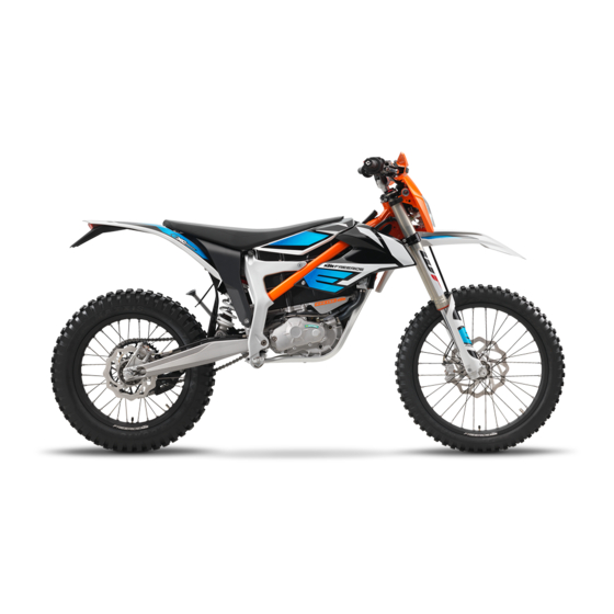
- Page 1 SETUP INSTRUCTIONS 2019 Freeride E‑XC Art. no. 3213880en...
- Page 3 KTM accepts no liability for delivery options, deviations from fig- ures and descriptions, misprints, and other errors. The models portrayed partly contain special equipment that does not belong to the regular scope of supply.
-
Page 4: Means Of Representation
Indicates an unexpected reaction (e.g. of a work step or a function). Identifies work requiring expert knowledge and technical understanding. In the interest of your own safety, only have these jobs performed by correspondingly trained KTM technical person- nel. All work identified by this symbol requires a level 1 qualification for high-voltage systems. Only this qualification authorizes you to perform non-electro-technical work on a vehicle or on units with a high-voltage system. - Page 5 MEANS OF REPRESENTATION 1 Formats used The typographical formats used in this document are explained below. Proprietary name Indicates a proprietary name. Name ® Indicates a protected name. Brand™ Indicates a brand available on the open market. Underlined terms Refer to technical details of the vehicle or indicate technical terms, which are explained in the glossary.
-
Page 6: Safety Advice
2 SAFETY ADVICE Work rules The KTM PowerPack does not contain any parts that require maintenance. Do not open the KTM PowerPack under any circumstances. Special tools are necessary for certain tasks. The tools are not a component of the vehicle, but can be ordered using the number in parentheses. - Page 7 Contact the KTM customer service immediately if major damage to the rechargeable lithium-ion bat- tery (KTM PowerPack) has occurred. There is no particular fire hazard for this vehicle when the rechargeable lithium-ion battery (KTM PowerPack) is intact. However, should the vehicle catch fire, inform the fire brigade responsible that an electric vehicle with a...
-
Page 8: Transport Mode
To operate the vehicle, the vehicle electronics must be enabled. This process is conducted during initial setup in KTM Dealer.net. Enabling ensures that the initial setup in KTM Dealer.net is docu- mented. Enabling can be performed either temporarily, e.g. for a test ride, or permanently for vehicle handover. - Page 9 SETUP 3 – Have a lift stand available. Lift stand (78129955100) – Carefully loosen and remove the tension belt of the footrest bracket. Info An assistant prevents the motorcycle from falling over. F01844-10 – Together with an assistant, take the vehicle off the pallet. –...
- Page 10 3 SETUP – Remove screws . Take off handlebar supports. – Place handlebar supports in required position. Mount and tighten screws Guideline Screw, handle- 40 Nm (29.5 lbf ft) Loctite ® 243™ bar support Info F01852-10 The handlebar supports can be mounted in four differ- ent positions.
- Page 11 SETUP 3 – Position the controls on the right half of the handlebar. – Route the cable without tension and secure with cable ties and cable holders. F01846-01 – Mount turn signal switch and route cable to the front. 402390-01 –...
- Page 12 3 SETUP – Mount the mirror clamps on both sides. H01060-01 – Mount and tighten the rear mirror on both sides. F01859-01 – Preassemble the hand guards on the left and right. E00962-01...
- Page 13 SETUP 3 – Mount the left hand guard. – Mount the right hand guard. F01860-10 – Position the front fender. Mount and tighten screws Guideline Remaining screws, 10 Nm (7.4 lbf ft) chassis – Mount and tighten screws Guideline Remaining screws, 10 Nm (7.4 lbf ft) chassis F01845-10...
- Page 14 3 SETUP – Position the turn signal on the headlight mask on both sides, mount nuts with washers and tighten. – Mount turn signal relay with lock washer screw F01854-10 – Position the turn signal on both sides on the license plate holder, mount nuts with washers and tighten.
- Page 15 SETUP 3 – Position turn signal indicator lamp in the combination instrument rack. F01857-10 – Join plug-in connector of the turn signal cable. – Make sure that the bulb is located in socket » If there is no bulb in the socket: –...
- Page 16 3 SETUP – Drill a hole at marking to the size of the marking. F01868-10 – Route the turn signal cable harness through the frame from the front to the rear paying attention to the plugs as you do so. F01869-10 –...
- Page 17 SETUP 3 – Route turn signal cable to the rear through the license plate holder extension. F01866-01 – Make sure that the bulb is located in the socket. » If there is no bulb in the socket: – Insert the bulb included in the accessory pack in the socket.
- Page 18 Set the kilometers or miles. ( p. 35) – Set the clock. ( p. 36) – Position all controls in their exact positions on the handlebar. F01875-10 Tighten all screws. – Unpack and mount the KTM PowerParts included in the deliv- ery (optional).
- Page 19 SETUP 3 Info Read the accompanying KTM PowerParts fitting instruc- tions. – Remove remaining protective film. – Attach the stickers included in the scope of supply (optional). – Prepare the vehicle according to the specifications in the KTM Dealer.net for handover to the customer.
- Page 20 22) – Remove the KTM PowerPack. p. 29) (Option: HV 2 technical personnel) – Ascertain that the KTM PowerPack is at zero potential. p. 36) – Ascertain that the discharge plug is de-energized. p. 37) – Mount the protection cap.
- Page 21 Remove the ignition key. A00169-11 Mounting the protection cap Note Material damage Components damaged or destroyed by water or dirt. – Mount the protection cap after you have removed the KTM PowerPack. Preparatory work – Deactivate the vehicle. p. 19) –...
- Page 22 4 WORK Removing the protection cap Note Material damage Components damaged or destroyed by water or dirt. – Mount the protection cap after you have removed the KTM PowerPack. Main work – Remove protection cap with one hand. F01672-10 Finishing work –...
- Page 23 Guideline Screw, fork stub 15 Nm (11.1 lbf ft) Finishing work – Install the KTM PowerPack. p. 30) (Option: HV 2 technical personnel) – Perform an equipotential bonding check (KTM PowerPack installed). p. 37) – Lock the seat. p. 22)
- Page 24 Locking the seat – Fold down the seat and push it down. The seat engages with an audible click. – Finally, check that the seat is correctly locked. F01671-10 4.10 Unlocking procedure for KTM PowerPack Condition The KTM PowerPack has been removed.
-
Page 25: Positioning The Battery Charger
Ensure that no fluids flow or drip onto the battery charger. Warning Risk of injury If the battery charger is used incorrectly, its intrinsic safety cannot be guaranteed. The battery charger is only suitable for use with a KTM PowerPack. – Only use the battery charger with a KTM PowerPack. - Page 26 4 WORK Info The battery charger contains sensitive electronics and must be handled with appropriate care. The battery charger may be damaged or destroyed if it is dropped, knocked or otherwise subject to mechanical overload. When transporting the battery charger, ensure appropriate means of securing the cargo. Damage caused due to improper handling or improper transport is excluded from the manufacturer war- ranty.
- Page 27 If the vehicle is activated while the vehicle is being charged with the KTM PowerPack installed, the vehi- cle switches to the fault state. The KTM PowerPack will continue to be recharged, however the 12 V bat- tery will stop recharging.
- Page 28 Switch on the battery charger using switch Charging starts automatically. The status indicator flashes during the charging process. C00769-10 – Monitor the charging level of the KTM PowerPack using the LEDs. LED 1: 20 % LED 2: 40 % C00770-10...
-
Page 29: Charging The 12-V Battery
After several seconds, all LEDs on the battery charger go out. – Disconnect the battery charger power plug from the mains con- nection. – Disconnect the charging cable from the KTM PowerPack. Guideline Pull on the structured part of the connector. Do not pull on C00769-11 the cable. –... - Page 30 The 12-V battery is maintenance-free. The acid level does not have to be checked. Info The 12-V battery is recharged by the KTM PowerPack when operating the vehicle. When the KTM PowerPack is recharged in the vehicle, then the 12-V battery is also recharged. Preparatory work –...
- Page 31 Environmental hazard A lithium-ion battery (KTM PowerPack) contains components and elements that are harmful to the environment. – Never throw a KTM PowerPack into the household trash. – Dispose of the KTM PowerPack properly and in compliance with the applicable regulations. Preparatory work – Deactivate the vehicle. p. 19) –...
- Page 32 Note Material damage Components damaged or destroyed by water or dirt. – Before installing the KTM PowerPack, check that the battery discharge plug on the electric motor and the bat- tery discharge socket on the KTM PowerPack are clean. – Check the battery discharge plug form ring.
- Page 33 WORK 4 4.17 Removing the 12 V battery Warning Risk of injury Battery gases cause serious chemical burns. – Keep the 12 V batteries out of the reach of children. – Wear suitable protective clothing and safety glasses. – Avoid contact with battery gases. –...
- Page 34 Install the headlight mask with the headlight. p. 33) – Install the KTM PowerPack. p. 30) (Option: HV 2 technical personnel) – Perform an equipotential bonding check (KTM PowerPack installed). p. 37) – Lock the seat. p. 22) – Check the headlight setting.
- Page 35 A00196-12 Finishing work – Install the KTM PowerPack. p. 30) (Option: HV 2 technical personnel) – Perform an equipotential bonding check (KTM PowerPack installed). p. 37) – Lock the seat. p. 22) – Check the headlight setting. p. 33) 4.21...
- Page 36 4 WORK Guideline 5 m (16 ft) Distance – The rider now sits down on the motorcycle with a full set of protective clothing. – Turn the ignition key in the ignition lock to the position – Push the main switch into the position –...
- Page 37 WORK 4 Info If no button is pressed for 10 - 12 seconds, the settings are automatically saved. If no button is pressed for 20 seconds, or if an impulse comes from the wheel speed sensor, the settings are automatically saved and the setup menu is closed. –...
- Page 38 4.26 Ascertaining that the KTM PowerPack is at zero potential Warning Risk of injury The measuring points could be live. – Use personal protective clothing and comply with the safety measures.
- Page 39 309699-10 Finishing work – Mount the protection cap. p. 19) 4.28 Performing an equipotential bonding check (KTM PowerPack installed) Warning Risk of injury The measuring points could be live. – Use personal protective clothing and comply with the safety measures. Condition The KTM PowerPack has been removed.
- Page 40 Spray silicone spray onto the new form ring. – Mount the form ring. 309693-10 Finishing work – Install the KTM PowerPack. p. 30) (Option: HV 2 technical personnel) – Perform an equipotential bonding check (KTM PowerPack installed). p. 37) – Lock the seat. p. 22)
-
Page 41: Technical Data
Screw, shock absorber adjusting 5 Nm (3.7 lbf ft) ring Screws, throttle grip 3 Nm (2.2 lbf ft) KTM PowerPack attachment 10 Nm (7.4 lbf ft) Remaining nuts, chassis 10 Nm (7.4 lbf ft) Remaining screws, chassis 10 Nm (7.4 lbf ft) Screw for spoiler attachment 5 Nm (3.7 lbf ft) - Page 42 5 TECHNICAL DATA Screw, motor guard 30 Nm (22.1 lbf ft) Screw, subframe top 45 Nm (33.2 lbf ft) Loctite ® 243™ Screw, bottom shock absorber 80 Nm (59 lbf ft) Loctite ® 2701™ Screw, top shock absorber 80 Nm (59 lbf ft) Loctite ®...
-
Page 43: Auxiliary Substances
AUXILIARY SUBSTANCES 6 Long-life grease Recommended supplier MOTOREX ® – Bike Grease 2000... - Page 44 *3213880en* 3213880en 01/2019 KTM Sportmotorcycle GmbH 5230 Mattighofen/Austria Photo: Mitterbauer/KISKA/KTM http://www.ktm.com...