
Related Manuals for Endress+Hauser Hart Proline Promag P 500


Summary of Contents for Endress+Hauser Hart Proline Promag P 500
- Page 1 Products Solutions Services BA01399D/06/EN/03.17 71389290 Valid as of version 01.01.zz (Device firmware) Operating Instructions Proline Promag P 500 HART Electromagnetic flowmeter...
- Page 2 • The manufacturer reserves the right to modify technical data without prior notice. Your Endress+Hauser Sales Center will supply you with current information and updates to these instructions. Endress+Hauser...
-
Page 3: Table Of Contents
......5.2.2 Measuring devices with lifting lugs . . 5.2.3 Transporting with a fork lift ..22 Endress+Hauser... - Page 4 12.3.1 Diagnostic message ... . . 152 10.4.2 Setting the system units ..12.3.2 Calling up remedial measures ..154 10.4.3 Displaying the I/O configuration ..98 Endress+Hauser...
- Page 5 13.2 Measuring and test equipment ... 170 13.3 Endress+Hauser services ....170 Repairs ......171 14.1 General notes .
-
Page 6: About This Document
• Inner ground terminal: Connects the protectiv earth to the mains supply. • Outer ground terminal: Connects the device to the plant grounding system. 1.2.3 Communication symbols Symbol Meaning Wireless Local Area Network (WLAN) Communication via a wireless, local network. Light emitting diode is off. Endress+Hauser... -
Page 7: Tool Symbols
Result of a step. Help in the event of a problem. Visual inspection. 1.2.6 Symbols in graphics Symbol Meaning 1, 2, 3, ... Item numbers , … Series of steps A, B, C, ... Views A-A, B-B, C-C, ... Sections Hazardous area Endress+Hauser... -
Page 8: Documentation
• The W@M Device Viewer : Enter the serial number from the nameplate (www.endress.com/deviceviewer) • The Endress+Hauser Operations App: Enter the serial number from the nameplate or scan the 2-D matrix code (QR code) on the nameplate. For a detailed list of the individual documents along with the documentation code →... -
Page 9: Basic Safety Instructions
Danger of breakage due to corrosive or abrasive fluids! ‣ Verify the compatibility of the process fluid with the sensor material. ‣ Ensure the resistance of all fluid-wetted materials in the process. ‣ Keep within the specified pressure and temperature range. Endress+Hauser... -
Page 10: Workplace Safety
Verification for borderline cases: ‣ For special fluids and fluids for cleaning, Endress+Hauser is glad to provide assistance in verifying the corrosion resistance of fluid-wetted materials, but does not accept any warranty or liability as minute changes in the temperature, concentration or level of contamination in the process can alter the corrosion resistance properties. -
Page 11: It Security
• WLAN passphrase The network key protects a connection between an operating unit (e.g. notebook or tablet) and the device via the WLAN interface which can be ordered as an option. Endress+Hauser... -
Page 12: Access Via Fieldbus
The device can be connected to a network via the CDI-RJ45 service interface. Device- specific functions guarantee the secure operation of the device in a network. It is advisable to take relevant security concepts into consideration, such as those issued by the Federal Office for Information Security. This includes organizational security measures Endress+Hauser... - Page 13 Proline Promag P 500 HART Basic safety instructions such as the assignment of access authorization as well as technical measures such as network segmentation. Endress+Hauser...
-
Page 14: Product Description
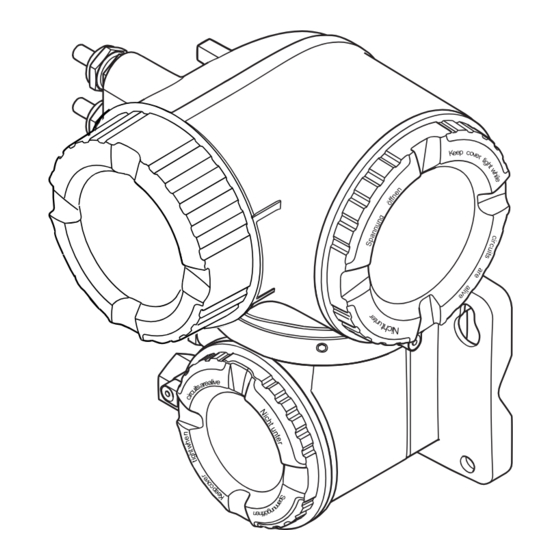
• A standard cable can be used as the connecting cable. • Not sensitive to external EMC interference. A0029593 1 Important components of a measuring device Electronics compartment cover Display module Transmitter housing Sensor connection housing with integrated ISEM electronics: connecting cable connection Sensor Endress+Hauser... - Page 15 I/ O – A0029589 2 Important components of a measuring device Connection compartment cover Display module Transmitter housing with integrated ISEM electronics Electronics compartment cover Sensor Sensor connection housing: connecting cable connection Connection compartment cover: connecting cable connection Endress+Hauser...
-
Page 16: Incoming Acceptance And Product
A0028673 and documents present? • If one of the conditions is not satisfied, contact your Endress+Hauser Sales Center. • Depending on the device version, the CD-ROM might not be part of the delivery! The Technical Documentation is available via the Internet or via the Endress+Hauser Operations App, see the "Product identification"... -
Page 17: Transmitter Nameplate
"Supplementary device-dependent documentation" → 8 • The W@M Device Viewer: Enter the serial number from the nameplate (www.endress.com/deviceviewer) • The Endress+Hauser Operations App: Enter the serial number from the nameplate or scan the 2-D matrix code (QR code) on the nameplate. 4.2.1 Transmitter nameplate Proline 500 –... - Page 18 Firmware version (FW) and device revision (Dev.Rev.) from the factory Space for additional information in the case of special products Permitted temperature range for cable Permitted ambient temperature (T Information on cable gland Available inputs and outputs, supply voltage Electrical connection data: supply voltage Endress+Hauser...
-
Page 19: Sensor Nameplate
(e.g. LA). If other optional specifications are also ordered, these are indicated collectively using the # placeholder symbol (e.g. #LA#). • If the ordered optional specifications do not include any safety and approval-related specifications, they are indicated by the + placeholder symbol (e.g. XXXXXX-ABCDE Endress+Hauser... -
Page 20: Symbols On Measuring Device
This symbol alerts you to a dangerous situation. Failure to avoid this situation can result in serious or fatal injury. Reference to documentation Refers to the corresponding device documentation. Protective ground connection A terminal which must be connected to ground prior to establishing any other connections. Endress+Hauser... -
Page 21: Storage And Transport
Center of gravity of the measuring device is higher than the suspension points of the webbing slings. Risk of injury if the measuring device slips. ‣ Secure the measuring device against slipping or turning. ‣ Observe the weight specified on the packaging (stick-on label). A0029214 Endress+Hauser... -
Page 22: Measuring Devices With Lifting Lugs
• Seaworthy packaging (optional): Wood crate, treated in accordance with ISPM 15 standard, which is confirmed by the affixed IPPC logo. • Carrying and mounting hardware: – Disposable plastic pallet – Plastic straps – Plastic adhesive strips • Dunnage: Paper cushion Endress+Hauser... -
Page 23: Installation
This measure also prevents the system losing prime. A0028981 6 Installation in a down pipe Vent valve Pipe siphon Length of down pipe Installation in partially filled pipes A partially filled pipe with a gradient necessitates a drain-type configuration. A0029257 Endress+Hauser... - Page 24 • Empty pipe detection only works if the transmitter housing is pointing upwards as otherwise there is no guarantee that the empty pipe detection function will actually respond to a partially filled or empty measuring tube. Endress+Hauser...
- Page 25 8 Order code for "Design", option C "Insertion length short ISO/DVGW until DN300, w/o inlet and outlet runs, constricted meas.tube" Installation dimensions For the dimensions and installation lengths of the device, see the "Technical Information" document, "Mechanical construction" section. Endress+Hauser...
-
Page 26: Requirements From Environment And Process
In the event of very strong vibrations, the pipe and sensor must be supported and fixed. • Information on the shock resistance of the measuring system → 187 • Information on the vibration resistance of the measuring system → 186 Endress+Hauser... - Page 27 2. From the nomogram read off the pressure loss as a function of flow velocity (downstream from the reduction) and the d/D ratio. [mbar] 8 m/s 7 m/s 6 m/s 5 m/s 4 m/s 3 m/s max. 8° 2 m/s 1 m/s d / D A0029002 Endress+Hauser...
-
Page 28: Special Mounting Instructions
– Open-ended wrench AF 10 – Torx screwdriver TX 25 • Proline 500 transmitter Open-ended wrench AF 13 For wall mounting: Drill with drill bit ⌀ 6.0 mm For sensor For flanges and other process connections: Corresponding mounting tools Endress+Hauser... -
Page 29: Preparing The Measuring Device
2. For "PFA" lining: generally additional seals are not required. 3. For "PTFE" lining: generally additional seals are not required. Mounting the ground cable/ground disks Comply with the information on potential equalization and detailed mounting instructions for the use of ground cables/ground disks . Endress+Hauser... - Page 30 16 × M27 – PN 25 16 × M33 – PN 10 20 × M24 – PN 16 20 × M27 – PN 25 20 × M33 – PN 10 20 × M24 – PN 16 20 × M30 – Endress+Hauser...
- Page 31 34 (25) 31 (23) Class 150 4 × 5/8 47 (35) 44 (32) Class 300 8 × 5/8 23 (17) 22 (16) Class 150 4 × 5/8 79 (58) 67 (49) Class 300 8 × ¾ 47 (35) 42 (31) Endress+Hauser...
- Page 32 8 × M16 8 × M20 8 × M20 8 × M22 8 × M20 12 × M22 12 × M20 12 × M22 12 × M22 – 12 × M24 – 16 × M22 – 16 × M24 – Endress+Hauser...
-
Page 33: Mounting The Transmitter Housing: Proline 500 - Digital
If operating outdoors: Avoid direct sunlight and exposure to weathering, particularly in warm climatic regions. CAUTION Excessive force can damage the housing! ‣ Avoid excessive mechanical stress. The transmitter can be mounted in the following ways: • Post mounting • Wall mounting Endress+Hauser... - Page 34 Engineering unit mm (in) Depends on order code for "Transmitter housing" Order code for "Transmitter housing" • Option A, aluminum coated: L =14 mm (0.55 in) • Option D, polycarbonate: L = 13 mm (0.51 in) 1. Drill the holes. Endress+Hauser...
-
Page 35: Mounting The Transmitter Housing: Proline 500
1. Drill the holes. 2. Insert wall plugs into the drilled holes. 3. Screw in the securing screws slightly at first. 4. Fit the transmitter housing over the securing screws and mount in place. 5. Tighten the securing screws. Endress+Hauser... -
Page 36: Turning The Transmitter Housing: Proline 500
1. Depending on the device version: Loosen the securing clamp of the connection compartment cover. 2. Unscrew the connection compartment cover. 3. Release the fixing screw. 4. Turn the housing to the desired position. 5. Firmly tighten the securing screw. 6. Screw on the connection compartment cover Endress+Hauser... -
Page 37: Turning The Display Module: Proline 500
Does the arrow on the sensor nameplate match the direction of flow of the fluid through the piping ? Are the measuring point identification and labeling correct (visual inspection)? Is the device adequately protected from precipitation and direct sunlight? Have the fixing screws been tightened with the correct tightening torque? Endress+Hauser... -
Page 38: Electrical Connection
Current output 4 to 20 mA HART A shielded cable is recommended. Observe grounding concept of the plant. Current output 0/4 to 20 mA Standard installation cable is sufficient. Pulse/frequency/switch output Standard installation cable is sufficient. Double pulse output Standard installation cable is sufficient. Endress+Hauser... - Page 39 Transmitter and sensor installed in the hazardous area: Zone 2; Class I, Division 2 oder Zone 1; Class I, Division 1 A: Connecting cable between sensor and transmitter: Proline 500 – digital Standard cable A standard cable with the following specifications can be used as the connecting cable. Endress+Hauser...
- Page 40 Coil current cable Design 3 × 0.75 mm (18 AWG) with common, braided copper shield (⌀ 9 mm (0.35 in)) and individual shielded cores Conductor resistance ≤37 Ω/km (0.011 Ω/ft) Capacitance: core/core, ≤120 pF/m (37 pF/ft) shield grounded Endress+Hauser...
-
Page 41: Terminal Assignment
Supply voltage Input/output Input/output Input/output Input/output 1 (+) 2 (–) 26 (+) 27 (–) 24 (+) 25 (–) 22 (+) 23 (–) 20 (+) 21 (–) Device-specific terminal assignment: adhesive label in terminal cover. Endress+Hauser... -
Page 42: Preparing The Measuring Device
1. Remove dummy plug if present. 2. If the measuring device is supplied without cable glands: Provide suitable cable gland for corresponding connecting cable. 3. If the measuring device is supplied with cable glands: Observe requirements for connecting cables → 38. Endress+Hauser... -
Page 43: Preparing The Connecting Cable: Proline 500 - Digital
2. In the case of the coil current cable: Insulate one core of the three-core cable at the level of the core reinforcement. You only require two cores for the connection. 3. For cables with fine-wire cores (stranded cables): Fit the cores with ferrules. Endress+Hauser... - Page 44 A = Terminate the cable B = Fit ferrules on cables with fine-wire cores (stranded cables) 1 = Red ferrules, 1.0 mm (0.04 in) 2 = White ferrules, 0.5 mm (0.02 in) * = Stripping only for reinforced cables Endress+Hauser...
-
Page 45: Connecting The Measuring Device: Proline 500 - Digital
Connection via terminals with order code for "Sensor connection housing": – Option A "Aluminum, coated"→ 46 – Option L "Cast, stainless"→ 46 Connecting the connecting cable to the transmitter The cable is connected to the transmitter via terminals → 47. Endress+Hauser... - Page 46 Housing degree of protection voided due to insufficient sealing of the housing. ‣ Screw in the thread on the cover without using any lubricant. The thread on the cover is coated with a dry lubricant. 8. Screw on the housing cover. 9. Tighten the securing clamp of the housing cover. Endress+Hauser...
- Page 47 This concludes the process for connecting the connecting cable. 9. Close the housing cover. 10. Tighten the securing screw of the housing cover. 11. After connecting the connecting cable: Connect the signal cable and the supply voltage cable → 48. Endress+Hauser...
-
Page 48: Connecting The Signal Cable And The Supply Voltage Cable
Supply voltage terminal assignment: Adhesive label in the terminal cover or → 41. 8. Firmly tighten the cable glands. This concludes the cable connection process. 9. Close the terminal cover. 10. Close the housing cover. Endress+Hauser... - Page 49 A0029598 17 Engineering unit mm (in) 1. To remove a cable from the terminal, use a flat-blade screwdriver to push the slot between the two terminal holes 2. while simultaneously pulling the cable end out of the terminal. Endress+Hauser...
-
Page 50: Connecting The Measuring Device: Proline 500
Connecting the connecting cable to the sensor connection housing Connection via terminals with order code for "Housing": Option A "Aluminum coated"→ 51 Connecting the connecting cable to the transmitter The cable is connected to the transmitter via terminals → 52. Endress+Hauser... - Page 51 Housing degree of protection voided due to insufficient sealing of the housing. ‣ Screw in the thread on the cover without using any lubricant. The thread on the cover is coated with a dry lubricant. 8. Screw on the housing cover. 9. Tighten the securing clamp of the housing cover. Endress+Hauser...
- Page 52 This concludes the process for connecting the connecting cables. 8. Screw on the connection compartment cover. 9. Tighten the securing clamp of the connection compartment cover. 10. After connecting the connecting cables: Connect the signal cable and the supply voltage cable → 53. Endress+Hauser...
-
Page 53: Connecting The Signal Cable And The Supply Voltage Cable
ö ff I/ O I/ O N ic ri r iz e e rg s io te n I/ O – – A0029814 5. Attach the holder to the edge of the electronics compartment. 6. Open the terminal cover. Endress+Hauser... - Page 54 This concludes the cable connection process. 12. Close the terminal cover. 13. Fit the display module holder in the electronics compartment. 14. Screw on the connection compartment cover. 15. Secure the securing clamp of the connection compartment cover. Endress+Hauser...
-
Page 55: Ensure Potential Equalization
19 Potential equalization via measuring tube 7.4.3 Connection example in special situations Unlined and ungrounded metal pipe This connection method also applies in situations where: • The customary potential equalization is not used • Equalizing currents are present Endress+Hauser... - Page 56 This connection method is only used if the following two conditions are met: • Metal pipe without liner or pipe with electrically conductive liner • Cathodic protection is integrated in the personal protection equipment Ground cable Copper wire, at least 6 mm (0.0093 in Endress+Hauser...
-
Page 57: Special Connection Instructions
Cable shield: the cable shield must be grounded at both ends to comply with EMC requirements; observe cable specifications Connection for HART operating devices → 83 Resistor for HART communication (≥ 250 Ω): observe maximum load → 179 Analog display unit: observe maximum load → 179 Transmitter Endress+Hauser... - Page 58 Pressure transmitter (e.g. Cerabar M, Cerabar S): see requirements Transmitter Current output 4-20 mA 4...20 mA A0028758 25 Connection example for 4-20 mA current output (active) Automation system with current input (e.g. PLC) Analog display unit: observe maximum load Transmitter Endress+Hauser...
- Page 59 Automation system with pulse/frequency input (e.g. PLC) Power supply Transmitter: Observe input values → 180 Switch output A0028760 28 Connection example for switch output (passive) Automation system with switch input (e.g. PLC) Power supply Transmitter: Observe input values → 180 Endress+Hauser...
- Page 60 Transmitter: Observe input values → 181 Double pulse output Double pulse output (slave), phase-shifted Relay output A0028760 31 Connection example for relay output (passive) Automation system with relay input (e.g. PLC) Power supply Transmitter: Observe input values → 181 Endress+Hauser...
-
Page 61: Ensuring The Degree Of Protection
1. Check that the housing seals are clean and fitted correctly. 2. Dry, clean or replace the seals if necessary. 3. Tighten all housing screws and screw covers. 4. Firmly tighten the cable glands. Endress+Hauser... -
Page 62: Post-Connection Check
Do the cables used meet the requirements? Do the cables have adequate strain relief? Are all the cable glands installed, firmly tightened and leak-tight? Cable run with "water trap" → 61 ? Is the potential equalization established correctly ? Endress+Hauser... -
Page 63: Operation Options
Overview of operation options A0034513 Local operation via display module Computer with Web browser (e.g. Internet Explorer) or with operating tool (e.g. FieldCare, DeviceCare, AMS Device Manager, SIMATIC PDM) Field Xpert SFX350 or SFX370 Mobile handheld terminal Control system (e.g. PLC) Endress+Hauser... -
Page 64: Structure And Function Of The Operating
Submenu 1 Submenu n Diagnostics Parameter 1 Parameter n Submenu 1 Submenu n Operating menu for experts Expert Access status display Parameter n System Sensor Input Output Communication Application Diagnostics A0018237-EN 34 Schematic structure of the operating menu Endress+Hauser... -
Page 65: Operating Philosophy
Configuration of the digital communication interface and the Web server. • Application Configure the functions that go beyond the actual measurement (e.g. totalizer). • Diagnostics Error detection and analysis of process and device errors and for device simulation and Heartbeat Technology. Endress+Hauser... -
Page 66: Access To The Operating Menu Via The Local Display
In the display area, each measured value is prefaced by certain symbol types for further description: Measured variable Measurement channel Diagnostic behavior number ↓ ↓ ↓ Example Appears only if a diagnostics event is present for this measured variable. Measured values Symbol Meaning Volume flow Conductivity Endress+Hauser... -
Page 67: Navigation View
• In the submenu: Omission symbol for Name of current Display symbol for menu operating menu levels in • Submenu • In the wizard: between • Wizard Display symbol for wizard • Parameters ↓ ↓ ↓ Examples / ../ Display Endress+Hauser... - Page 68 No display symbol exists for parameters in submenus. Locking Symbol Meaning Parameter locked When displayed in front of a parameter name, indicates that the parameter is locked. • By a user-specific access code • By the hardware write protection switch Endress+Hauser...
-
Page 69: Editing View
M N O P Q R S T U V W A0034114 36 For entering text in parameters (e.g. tag name) Entry display area Current input screen Change input screen Operating elements Move entry position Delete entry Reject or confirm entry Endress+Hauser... - Page 70 Umlauts and accents Controlling data entries Symbol Meaning Move entry position Reject entry Confirm entry Delete character immediately to the left of the entry position Delete character immediately to the right of the entry position Clear all the characters entered Endress+Hauser...
-
Page 71: Operating Elements
Press the key for 3 s: deactivate the keypad lock. 8.3.5 Opening the context menu Using the context menu, the user can call up the following menus quickly and directly from the operational display: • Setup • Data backup • Simulation Endress+Hauser... - Page 72 The context menu is closed and the operational display appears. Calling up the menu via the context menu 1. Open the context menu. 2. Press to navigate to the desired menu. 3. Press to confirm the selection. The selected menu opens. Endress+Hauser...
-
Page 73: Navigating And Selecting From List
A parameter number is assigned to every parameter to be able to access a parameter directly via the onsite display. Entering this access code in the Direct access parameter calls up the desired parameter directly. Navigation path Expert → Direct access Endress+Hauser... -
Page 74: Calling Up Help Text
Parameters can be changed via the numeric editor or text editor. • Numeric editor: Change values in a parameter, e.g. specifications for limit values. • Text editor: Enter text in a parameter, e.g. tag name. A message is displayed if the value entered is outside the permitted value range. Endress+Hauser... -
Page 75: User Roles And Related Access Authorization
Parameter write protection via local operation can be disabled by entering the user-specific access code in the Enter access code parameter (→ 119) via the respective access option. 1. After you press , the input prompt for the access code appears. Endress+Hauser... -
Page 76: Enabling And Disabling The Keypad
WLAN connection: order code for "Display; operation", option G "4-line, illuminated; touch control + WLAN". The device acts as an Access Point and enables communication by computer or a mobile handheld terminal. For additional information on the Web server, refer to the Special Documentation for the device Endress+Hauser... -
Page 77: Prerequisites
Network connections Only the active network connections to the measuring device should be used. Switch off all other network Switch off all other network connections such as WLAN. connections. In the event of connection problems: → 147 Endress+Hauser... -
Page 78: Establishing A Connection
3. If a 2nd network card is not used, close all the applications on the notebook. Applications requiring Internet or a network, such as e-mail, SAP applications, Internet or Windows Explorer. 4. Close any open Internet browsers. 5. Configure the properties of the Internet protocol (TCP/IP) as defined in the table: Endress+Hauser... - Page 79 SSID name to the measuring point (e.g. tag name) because it is displayed as the WLAN network. Disconnecting ‣ After configuring the device: Terminate the WLAN connection between the operating unit and measuring device. Starting the Web browser 1. Start the Web browser on the computer. Endress+Hauser...
-
Page 80: Logging On
2. Enter the user-specific access code. 3. Press OK to confirm your entry. Access code 0000 (factory setting); can be changed by customer If no action is performed for 10 minutes, the Web browser automatically returns to the login page. Endress+Hauser... -
Page 81: User Interface
End the operation and call up the login page Navigation area If a function is selected in the function bar, the submenus of the function open in the navigation area. The user can now navigate through the menu structure. Endress+Hauser... -
Page 82: Disabling The Web Server
Reset modified properties of the Internet protocol (TCP/IP) → 78. Access to the operating menu via the operating tool The structure of the operating menu in the operating tools is the same as for operation via the local display. Endress+Hauser... -
Page 83: Connecting The Operating Tool
Computer with Web browser (e.g. Internet Explorer) for accessing the integrated device Web server or computer with operating tool (e.g. FieldCare, DeviceCare, AMS Device Manager, SIMATIC PDM) with COM DTM "CDI Communication TCP/IP" Commubox FXA195 (USB) Field Xpert SFX350 or SFX370 VIATOR Bluetooth modem with connecting cable Transmitter Endress+Hauser... - Page 84 Service interface (CDI-RJ45) of the measuring device with access to the integrated Web server Via WLAN interface The optional WLAN interface is available on the following device version: Order code for "Display; operation", option G "4-line, illuminated, graphic display; touch control + WLAN" Endress+Hauser...
- Page 85 • Angle bracket: Stainless steel Configuring the Internet protocol of the mobile terminal NOTICE If the WLAN connection is lost during the configuration, settings made may be lost. ‣ Make sure that the WLAN connection is not disconnected while configuring the device. Endress+Hauser...
-
Page 86: Field Xpert Sfx350, Sfx370
FieldCare Function scope FDT-based plant asset management tool from Endress+Hauser. It can configure all smart field devices in a system and helps you manage them. By using the status information, it is also a simple but effective way of checking their status and condition. - Page 87 The CDI Communication TCP/IP (Configuration) window opens. 6. Enter the device address in the IP address field: 192.168.1.212 and press Enter to confirm. 7. Establish the online connection to the device. For additional information, see Operating Instructions BA00027S and BA00059S Endress+Hauser...
-
Page 88: Devicecare
DeviceCare Function scope Tool to connect and configure Endress+Hauser field devices. The fastest way to configure Endress+Hauser field devices is with the dedicated "DeviceCare" tool. Together with the device type managers (DTMs) it presents a convenient, comprehensive solution. For details, see Innovation Brochure IN01047S Source for device description files See information →... -
Page 89: Simatic Pdm
Source for device description files See data → 90 8.5.7 Field Communicator 475 Function scope Industrial handheld terminal from Emerson Process Management for remote configuration and measured value display via HART protocol. Source for device description files See data → 90 Endress+Hauser... -
Page 90: System Integration
Operating tool via Sources for obtaining device descriptions HART protocol FieldCare • www.endress.com → Download Area • CD–ROM (contact Endress+Hauser) • DVD (contact Endress+Hauser) DeviceCare • www.endress.com → Download Area • CD–ROM (contact Endress+Hauser) • DVD (contact Endress+Hauser) •... - Page 91 • 4 = conductivity • 7 = electronic temperature • 8 = totalizer 1 • 9 = totalizer 2 • 10 = totalizer 3 Visibility depends on order options or device settings Visibility depends on order options or device settings Endress+Hauser...
-
Page 92: Other Settings
X. • On Burst command 1 to n Select the HART command that is sent to the • Command 1 Command 2 HART master. • Command 2 • Command 3 • Command 9 • Command 33 • Command 48 Endress+Hauser... - Page 93 Positive integer 1 000 ms burst commands of burst message X. Max. update period Enter the maximum time span between two Positive integer 2 000 ms burst commands of burst message X. Visibility depends on order options or device settings Endress+Hauser...
-
Page 94: Commissioning
Betrieb Setup A0029420 42 Taking the example of the local display 10.4 Configuring the measuring device • The Setup menu with its guided wizards contains all the parameters needed for standard operation. • Navigation to the Setup menu Endress+Hauser... - Page 95 Relay output 1 to n → 114 ‣ Double pulse output → 116 ‣ Display → 109 ‣ Low flow cut off → 111 ‣ → 112 Empty pipe detection ‣ Advanced setup → 118 Endress+Hauser...
-
Page 96: Defining The Tag Name
System units Volume flow unit → 97 Volume unit → 97 Conductivity unit → 97 Temperature unit → 97 Mass flow unit → 97 Mass unit → 97 → 97 Density unit Endress+Hauser... - Page 97 Select corrected volume flow Unit choose list Country-specific: unit. • Nl/h • Sft³/h Result The selected unit applies for: Corrected volume flow parameter (→ 137) Corrected volume unit – Select corrected volume unit. Unit choose list Country-specific: • Nm³ • Sft³ Endress+Hauser...
-
Page 98: Displaying The I/O Configuration
Enter the code in order to change the I/O Positive integer configuration. Visibility depends on order options or device settings 10.4.4 Configuring the status input The Status input submenu guides the user systematically through all the parameters that have to be set for configuring the status input. Endress+Hauser... -
Page 99: Configuring The Current Input
The "Current input" wizard guides the user systematically through all the parameters that have to be set for configuring the current input. Navigation "Setup" menu → Current input ‣ Current input 1 to n → 100 Terminal number → 100 Signal mode Endress+Hauser... -
Page 100: Configuring The Current Output
Configuring the current output The Current output wizard guides you systematically through all the parameters that have to be set for configuring the current output. Navigation "Setup" menu → Current output ‣ Current output 1 to n → 101 Terminal number Endress+Hauser... - Page 101 One of the following options is Enter 4 mA value. Signed floating-point Country-specific: selected in the Current span number • 0 l/h parameter (→ 101): • 0 gal/min (us) • 4...20 mA NAMUR • 4...20 mA US • 4...20 mA • 0...20 mA Endress+Hauser...
- Page 102 • 4...20 mA • 0...20 mA Failure current The Defined value option is Enter current output value in 0 to 22.5 mA 22.5 mA selected in the Failure mode alarm condition. parameter. Visibility depends on order options or device settings Endress+Hauser...
-
Page 103: Configuring The Pulse/Frequency
→ 104 Terminal number → 104 Signal mode → 104 Assign pulse output → 104 Value per pulse → 104 Pulse width → 104 → 104 Failure mode Invert output signal → 104 Endress+Hauser... - Page 104 Invert output signal – Invert the output signal. • No • Yes Visibility depends on order options or device settings Configuring the frequency output Navigation "Setup" menu → Pulse/frequency/switch output ‣ Pulse/frequency/switch output 1 to n Operating mode → 105 Endress+Hauser...
- Page 105 One of the following options is Enter minimum frequency. 0.0 to 10 000.0 Hz 0.0 Hz selected in the Assign current output parameter (→ 101): • Volume flow • Mass flow • Corrected volume flow • Flow velocity • Conductivity • Electronic temperature Endress+Hauser...
- Page 106 (→ 101): • Volume flow • Mass flow • Corrected volume flow • Flow velocity • Conductivity • Electronic temperature Invert output signal – Invert the output signal. • No • Yes Visibility depends on order options or device settings Endress+Hauser...
- Page 107 Shows the terminal numbers • Not used – used by the PFS output • 24-25 (I/O 2) module. • 22-23 (I/O 3) • 20-21 (I/O 4) Signal mode – Select the signal mode for the • Passive Passive PFS output. • Active Endress+Hauser...
- Page 108 Switch-on delay • The Switch option is Define delay for the switch-on 0.0 to 100.0 s 0.0 s selected in the Operating of status output. mode parameter. • The Limit option is selected in the Switch output function parameter. Endress+Hauser...
-
Page 109: Configuring The Local Display
100% bargraph value 1 → 110 Value 2 display → 110 Value 3 display → 110 → 110 0% bargraph value 3 100% bargraph value 3 → 110 Value 4 display → 110 Endress+Hauser... - Page 110 Value 4 display A local display is provided. Select the measured value that For the picklist, see None is shown on the local display. the Value 2 display parameter (→ 110) Visibility depends on order options or device settings Endress+Hauser...
-
Page 111: Configuring The Low Flow Cut Off
One of the following options is Enter time frame for signal 0 to 100 s selected in the Assign process suppression (= active pressure variable parameter shock suppression). (→ 111): • Volume flow • Mass flow • Corrected volume flow Endress+Hauser... -
Page 112: 10.4.10 Configuring Empty Pipe Detection
S862 ' ' P ipe option is selected. empty' ' is displayed for empty pipe detection. 10.4.11 Configuring the HART input Navigation "Setup" menu → HART input ‣ HART input → 113 Capture mode Device ID → 113 Endress+Hauser... - Page 113 Capture • Command 9 mode parameter. • Command 33 Slot number The Burst network option or Define position of external 1 to 8 the Master network option is process variable in burst selected in the Capture mode command. parameter. Endress+Hauser...
-
Page 114: 10.4.12 Configuring The Relay Output
"Setup" menu → Relay output 1 to n ‣ RelaisOutput 1 to n Switch output function → 115 Assign flow direction check → 115 Assign limit → 115 Assign diagnostic behavior → 115 Assign status → 115 Endress+Hauser... - Page 115 Limit option is of status output. selected. Switch-on value In the Relay output function Enter measured value for the Signed floating-point Country-specific: parameter, the Limit option is switch-on point. number • 0 l/h selected. • 0 gal(us)/min Endress+Hauser...
-
Page 116: 10.4.13 Configuring The Double Pulse Output
Shows the terminal numbers used by the • Not used – master of the double pulse output module. • 24-25 (I/O 2) • 22-23 (I/O 3) Slave terminal number • Not used – • 24-25 (I/O 2) • 22-23 (I/O 3) Endress+Hauser... - Page 117 Define time width of the output pulse. 0.5 to 2 000 ms 0.5 ms Failure mode Define output behavior in alarm condition. • Actual value No pulses • No pulses Invert output signal Invert the output signal. • No • Yes Endress+Hauser...
-
Page 118: Advanced Settings
Special Documentation for the device. Navigation "Setup" menu → Advanced setup Advanced setup Enter access code → 119 ‣ Sensor adjustment → 119 ‣ Totalizer 1 to n → 119 ‣ SIL confirmation ‣ Deactivate SIL Endress+Hauser... -
Page 119: Using The Parameter To Enter The Access Code
Set sign of flow direction to match the • Flow in arrow direction Flow in arrow direction direction of the arrow on the sensor. • Flow against arrow direction 10.5.3 Configuring the totalizer In the "Totalizer 1 to n" submenu the individual totalizer can be configured. Endress+Hauser... - Page 120 – Select totalizer calculation • Net flow total Net flow total mode. • Forward flow total • Reverse flow total Failure mode – Define totalizer behavior in • Stop Stop alarm condition. • Actual value • Last valid value Endress+Hauser...
-
Page 121: Carrying Out Additional Display Configurations
→ 123 Decimal places 4 → 123 Display language → 123 Display interval → 123 Display damping → 123 Header → 123 Header text → 123 Separator → 124 Backlight → 124 Endress+Hauser... - Page 122 Value 2 display parameter (→ 110) 0% bargraph value 3 A selection was made in the Enter 0% value for bar graph Signed floating-point Country-specific: Value 3 display parameter. display. number • 0 l/h • 0 gal/min (us) Endress+Hauser...
- Page 123 • Device tag Device tag display. • Free text Header text In the Header parameter, the Enter display header text. Max. 12 characters ------------ Free text option is selected. such as letters, numbers or special characters (e.g. @, %, /) Endress+Hauser...
-
Page 124: Performing Electrode Cleaning
ECC recovery time For the following order code: Define recovery time after 1 to 600 s 60 s "Application package", option electrode cleaning. During this EC "ECC electrode cleaning" time the current output values will be held at last valid value. Endress+Hauser... -
Page 125: Wlan Configuration
4 octet: 0 to 255 (in 192.168.1.212 WLAN interface. the particular octet) Network security – Select the security type of the • Unsecured WPA2-PSK WLAN network. • WPA2-PSK • EAP-PEAP with MSCHAPv2 • EAP-PEAP MSCHAPv2 no server authentic. • EAP-TLS Endress+Hauser... -
Page 126: Configuration Management
Indicates how long the device has been in Days (d), hours (h), minutes – operation. (m) and seconds (s) Last backup Shows when the last data backup was saved Days (d), hours (h), minutes – to HistoROM backup. (m) and seconds (s) Endress+Hauser... -
Page 127: Using Parameters For Device Administration
While this action is in progress, the configuration cannot be edited via the local display and a message on the processing status appears on the display. 10.5.8 Using parameters for device administration The Administration submenu systematically guides the user through all the parameters that can be used for device administration purposes. Endress+Hauser... - Page 128 Restrict write-access to parameters to protect the configuration Max. 16-digit character string comprising of the device against unintentional changes. numbers, letters and special characters Confirm access code Confirm the entered access code. Max. 16-digit character string comprising numbers, letters and special characters Endress+Hauser...
-
Page 129: Simulation
Character string comprising 0x00 numbers, letters and special For a reset code, contact your characters Endress+Hauser service organization. The reset code can only be entered via: • Web browser • DeviceCare, FieldCare (via service interface CDI-RJ45) • Fieldbus Using the parameter to reset the device Navigation "Setup"... - Page 130 → 131 Switch status 1 to n → 131 Pulse output simulation → 132 Pulse value → 132 Device alarm simulation → 132 Diagnostic event category → 132 Diagnostic event simulation → 132 Endress+Hauser...
- Page 131 • On Switch status 1 to n The On option is selected in Select status of the relay • Open Open the Switch output simulation output for the simulation. • Closed 1 to n parameter parameter. Endress+Hauser...
-
Page 132: Protecting Settings From Unauthorized
2. Define a max. 16-digit character string comprising numbers, letters and special characters as the access code. 3. Enter the access code again in the Confirm access code parameter (→ 128) to confirm the code. The -symbol appears in front of all write-protected parameters. Endress+Hauser... - Page 133 Via Web browser, FieldCare, DeviceCare (via CDI-RJ45 service interface), fieldbus For a reset code, contact your Endress+Hauser service organization. 1. Navigate to the Reset access code parameter (→ 129). 2. Enter the reset code.
-
Page 134: Write Protection Via Write Protection
In the Locking status parameter the Hardware locked option is displayed → 136. In addition, on the local display the -symbol appears in front of the parameters in the header of the operational display and in the navigation view. X X X X X X X 20.50 A0029425 Endress+Hauser... - Page 135 (factory setting) disables hardware write protection. No option is displayed in the Locking status parameter → 136. On the local display, the -symbol disappears from in front of the parameters in the header of the operational display and in the navigation view. Endress+Hauser...
-
Page 136: Operation
The Process variables submenu contains all the parameters needed to display the current measured values for each process variable. Navigation "Diagnostics" menu → Measured values → Process variables ‣ Process variables Volume flow → 137 → 137 Mass flow Endress+Hauser... - Page 137 Positive floating-point • Order code for "Sensor option", option corrected. number CI "Medium temperature Dependency measurement" The unit is taken from the Conductivity unit parameter (→ 97). • The temperature is read into the flowmeter from an external device. Endress+Hauser...
-
Page 138: Totalizer" Submenu
The Input values submenu guides you systematically to the individual input values. Navigation "Diagnostics" menu → Measured values → Input values ‣ Input values ‣ Current input 1 to n → 139 ‣ Status input 1 to n → 139 Endress+Hauser... -
Page 139: Output Values
The Output values submenu contains all the parameters needed to display the current measured values for every output. Navigation "Diagnostics" menu → Measured values → Output values ‣ Output values ‣ Current output 1 to n → 140 Endress+Hauser... - Page 140 "Diagnostics" menu → Measured values → Output values → Pulse/frequency/switch output 1 to n ‣ Pulse/frequency/switch output 1 to n Output frequency 1 to n → 141 Pulse output 1 to n → 141 → 141 Switch status 1 to n Endress+Hauser...
- Page 141 "Diagnostics" menu → Measured values → Output values → Double pulse output ‣ Double pulse output → 141 Pulse output Parameter overview with brief description Parameter Description User interface Pulse output Shows the currently output pulse frequency. Positive floating-point number Endress+Hauser...
-
Page 142: Adapting The Measuring Device To The Process
The totaling process is stopped and the totalizer is reset to 0. Preset + hold The totaling process is stopped and the totalizer is set to its defined start value from the Preset value parameter. Reset + totalize The totalizer is reset to 0 and the totaling process is restarted. Endress+Hauser... -
Page 143: Function Scope Of The "Reset All Totalizers" Parameter
If the length of the logging interval or the assignment of the process variables to the channels is changed, the content of the data logging is deleted. Navigation "Diagnostics" menu → Data logging ‣ Data logging Assign channel 1 → 144 Assign channel 2 → 144 Assign channel 3 → 145 Endress+Hauser... - Page 144 Assign channel 2 The Extended HistoROM Assign process variable to Picklist, see Assign application package is logging channel. channel 1 parameter available. (→ 144) The software options currently enabled are displayed in the Software option overview parameter. Endress+Hauser...
- Page 145 • Active • Stopped Entire logging duration In the Data logging Displays the total logging Positive floating- parameter, the Not duration. point number overwriting option is selected. Visibility depends on order options or device settings Endress+Hauser...
-
Page 146: Diagnostics And Troubleshooting
Message on local display: Communication between the • Check the cable and the "Communication Error" display module and the electronics connector between the main "Check Electronics" is interrupted. electronics module and display module. • Order spare part → 171. Endress+Hauser... - Page 147 No WLAN network available • Check if WLAN reception is FieldCare or DeviceCare present: LED on display module is lit blue • Check if WLAN connection is enabled: LED on display module flashes blue • Switch on instrument function. Endress+Hauser...
-
Page 148: 12.2 Diagnostic Information Via Light Emitting
(via port 8000 or TFTP the network, the firewall must be ports) adapted or disabled to allow FieldCare/DeviceCare access. 12.2 Diagnostic information via light emitting diodes 12.2.1 Transmitter Proline 500 – digital Different LEDs in the transmitter provide information on the device status. Endress+Hauser... - Page 149 Communication Communication not active. White Communication active. Service interface (CDI) Not connected or no connection established. Yellow Connected and connection established. Flashing yellow Service interface active. Proline 500 Different LEDs in the transmitter provide information on the device status. Endress+Hauser...
-
Page 150: Sensor Connection Housing
Connected and connection established. Flashing yellow Service interface active. 12.2.2 Sensor connection housing Proline 500 – digital Various light emitting diodes (LED) on the ISEM electronics (Intelligent Sensor Electronic Module) in the sensor connection housing provide information on the device status. Endress+Hauser... - Page 151 Diagnostics and troubleshooting Communication Communication Alarm Power Power A0029699 Communication Device status Supply voltage Color Meaning Communication White Communication active Device status Error Flashing red Warning Supply voltage Green Supply voltage is ok Supply voltage is off or too low Endress+Hauser...
-
Page 152: Diagnostic Information On Local Display
• Outside its technical specification limits (e.g. outside the process temperature range) • Outside of the configuration carried out by the user (e.g. maximum flow in parameter 20 mA value) Maintenance required Maintenance is required. The measured value remains valid. Endress+Hauser... - Page 153 ↓ ↓ ↓ Example Curr.output 1 A0013962 A0013958 NAMUR 3-digit number NE 107 Operating elements Meaning Plus key In a menu, submenu Opens the message about remedy information. Enter key In a menu, submenu Opens the operating menu. Endress+Hauser...
-
Page 154: Calling Up Remedial Measures
The message for the remedial measures closes. 12.4 Diagnostic information in the Web browser 12.4.1 Diagnostic options Any faults detected by the measuring device are displayed in the Web browser on the home page once the user has logged on. Endress+Hauser... -
Page 155: Calling Up Remedy Information
Recommendation NE 107. 12.4.2 Calling up remedy information Remedy information is provided for every diagnostic event to ensure that problems can be rectified quickly. These measures are displayed in red along with the diagnostic event and the related diagnostic information. Endress+Hauser... -
Page 156: Diagnostic Information In Devicecare Or
Diagnostic information Diagnostic code Diagnostic Diagnostic Status signal Short text behavior number ↓ ↓ ↓ Example Curr.output 1 A0013962 A0013958 NAMUR 3-digit number NE 107 Endress+Hauser... -
Page 157: Calling Up Remedy Information
Adapting the status signal Each item of diagnostic information is assigned a specific status signal at the factory. The user can change this assignment for specific diagnostic information in the Diagnostic event category submenu. Expert → Communication → Diagnostic event category Endress+Hauser... -
Page 158: Overview Of Diagnostic Information
2. Replace sensor cable or sensor 3. Turn off temperature measurement Sensor connection 1. Check sensor cable and sensor Alarm 2. Execute Heartbeat Verification 3. Replace sensor cable or sensor Diagnostic of electronic Device failure 1. Restart device Alarm 2. Contact service Endress+Hauser... - Page 159 Sensor electronic (ISEM) 1. Replace sensor electronic module Warning faulty (ISEM) 2. Turn off diagnostic message Sensor electronic (ISEM) 1. Check sensor cable and sensor Warning faulty 2. Perform Heartbeat Verification 3. Replace sensor cable or sensor Endress+Hauser...
- Page 160 Current output 1 to n Deactivate simulation Warning simulation Simulation frequency Deactivate simulation frequency Warning output 1 to n output Simulation pulse output Deactivate simulation pulse output Warning 1 to n Switch output Deactivate simulation switch output Warning simulation 1 to n Endress+Hauser...
- Page 161 Low flow cut off active! Warning 1. Check low flow cut off configuration Input signal 1. Check input configuration Alarm 2. Check external device or process conditions Sensor symmetry 1. Eliminate external magnetic field Warning near sensor 2. Turn off diagnostic message Endress+Hauser...
-
Page 162: Pending Diagnostic Events
Previous diagnostics Two diagnostic events have already Shows the diagnostic event that Symbol for diagnostic occurred. occurred prior to the current diagnostic behavior, diagnostic code event along with its diagnostic and short message. information. Endress+Hauser... -
Page 163: Diagnostic List
• If the Extended HistoROM application package (order option) is enabled in the device, the event list can contain up to 100 entries . The event history includes entries for: • Diagnostic events → 158 • Information events → 164 Endress+Hauser... -
Page 164: 12.10.2 Filtering The Event Logbook
I1137 Electronic changed I1151 History reset I1155 Reset electronic temperature I1156 Memory error trend I1157 Memory error event list I1184 Display connected I1256 Display: access status changed I1264 Safety sequence aborted I1278 I/O module reset detected I1335 Firmware changed Endress+Hauser... - Page 165 Reset to factory settings I1635 Reset to delivery settings I1639 Max. switch cycles number reached I1643 Custody transfer logbook cleared I1649 Hardware write protection activated I1650 Hardware write protection deactivated I1651 Custody transfer parameter changed I1712 New flash file received Endress+Hauser...
-
Page 166: 12.11 Resetting The Measuring Device
→ 167 Device name → 167 Order code → 167 → 167 Extended order code 1 Extended order code 2 → 167 Extended order code 3 → 167 ENP version → 167 Endress+Hauser... - Page 167 (ENP). Device revision Shows the device revision with which the 2-digit hexadecimal number device is registered with the HART Communication Foundation. Device ID Shows the device ID for identifying the 6-digit hexadecimal number – device in a HART network. Endress+Hauser...
- Page 168 Shows the device type with which the 2-digit hexadecimal number 0x3A (for Promag 500) measuring device is registered with the HART Communication Foundation. Manufacturer ID Shows the manufacturer ID device is 2-digit hexadecimal number 0x11 (for Endress+Hauser) registered with the HART Communication Foundation. Endress+Hauser...
-
Page 169: 12.13 Firmware History
"Manufacturer' s information" document. The manufacturer' s information is available: • In the Download Area of the Endress+Hauser web site: www.endress.com → Downloads • Specify the following details: –... -
Page 170: Maintenance
Replacement seals (accessory part) → 202 13.2 Measuring and test equipment Endress+Hauser offers a wide variety of measuring and test equipment, such as W@M or device tests. Your Endress+Hauser Sales Center can provide detailed information on the services. List of some of the measuring and testing equipment: → 173 13.3... -
Page 171: Repairs
• The measuring devices have a modular design. • Spare parts are grouped into logical kits with the associated Installation Instructions. • Repairs are carried out by Endress+Hauser Service or by appropriately trained customers. • Certified devices can only be converted to other certified devices by Endress+Hauser Service or at the factory. -
Page 172: Disposal
Ensure that the measuring device and all cavities are free of fluid residues that are hazardous to health or the environment, e.g. substances that have permeated into crevices or diffused through plastic. Observe the following notes during disposal: ‣ Observe valid federal/national regulations. ‣ Ensure proper separation and reuse of the device components. Endress+Hauser... -
Page 173: Accessories
Various accessories, which can be ordered with the device or subsequently from Endress +Hauser, are available for the device. Detailed information on the order code in question is available from your local Endress+Hauser sales center or on the product page of the Endress+Hauser website: www.endress.com. -
Page 174: For The Sensor
For details, see "Technical Information" TI00025S and Operating Instructions BA00053S Fieldgate FXA520 Gateway for the remote diagnostics and remote configuration of connected HART measuring devices via a Web browser. For details, see "Technical Information" TI00025S and Operating Instructions BA00051S Endress+Hauser... -
Page 175: Service-Specific Accessories
Accessories Description Applicator Software for selecting and sizing Endress+Hauser measuring devices: • Choice of measuring devices for industrial requirements • Calculation of all the necessary data for identifying the optimum flowmeter: e.g. nominal diameter, pressure loss, flow velocity and accuracy. -
Page 176: Technical Data
(~ 2 pulse/s) (v ~ 0.04 m/s) (v ~ 2.5 m/s) [mm] [in] /min] /min] /min] ½ 4 to 100 9 to 300 – 15 to 500 1 ½ 25 to 700 35 to 1 100 – 60 to 2 000 Endress+Hauser... - Page 177 3600 600 to 19 000 4800 800 to 24 000 6000 1 000 to 30 000 7500 1 400 to 44 000 10500 Recommended measuring range "Flow limit" section → 189 Operable flow range Over 1000 : 1 Endress+Hauser...
- Page 178 • Reference density for calculating the corrected volume flow Various pressure transmitters and temperature measuring devices can be ordered from Endress+Hauser: see "Accessories" section → 175 It is recommended to read in external measured values to calculate the following measured...
-
Page 179: Output
0 to 700 Ω Resolution 0.38 µA Damping Adjustable: 0.07 to 999 s Assignable measured • Volume flow variables • Mass flow • Corrected volume flow • Flow velocity • Conductivity • Corrected conductivity • Temperature • Electronic temperature Endress+Hauser... - Page 180 • Conductivity • Corrected conductivity • Temperature • Electronic temperature Switch output Maximum input values DC 30 V, 250 mA (passive) Open-circuit voltage DC 28.8 V (active) Switching behavior Binary, conductive or non-conductive Switching delay Adjustable: 0 to 100 s Endress+Hauser...
- Page 181 • Flow velocity • Conductivity • Corrected conductivity • Temperature • Electronic temperature Relay output Function Switch output Version Relay output, galvanically isolated Switching behavior Can be set to: • NO (normally open), factory setting • NC (normally closed) Endress+Hauser...
- Page 182 • Last valid value 0 to 20 mA Failure mode Choose from: • Maximum alarm: 22 mA • Freely definable value between: 0 to 20.5 mA Pulse/frequency/switch output Pulse output Failure mode Choose from: • Actual value • No pulses Endress+Hauser...
- Page 183 • Device alarm/error has occurred Diagnostic information via light emitting diodes Low flow cut off The switch points for low flow cut off are user-selectable. Galvanic isolation The outputs are galvanically isolated from one another and from earth (PE). Endress+Hauser...
-
Page 184: Power Supply
Conductor cross-section 0.2 to 2.5 mm (24 to 12 AWG). Cable entries • Cable gland: M20 × 1.5 with cable ⌀ 6 to 12 mm (0.24 to 0.47 in) • Thread for cable entry: – NPT ½" – G ½" – M20 Endress+Hauser... -
Page 185: Performance Characteristics
The outputs have the following base accuracy specifications. Current output Accuracy ±5 µA Pulse/frequency output o.r. = of reading Accuracy Max. ±50 ppm o.r. (over the entire ambient temperature range) Repeatability o.r. = of reading Volume flow Max. ±0.1 % o.r. ± 0.5 mm/s (0.02 in/s) Endress+Hauser... -
Page 186: Installation
– 2 to 8.4 Hz, 7.5 mm peak – 8.4 to 2 000 Hz, 2 g peak • Vibration broad-band random, according to IEC 60068-2-64 – 10 to 200 Hz, 0.01 g – 200 to 2 000 Hz, 0.003 g – Total: 2.70 g rms Endress+Hauser... -
Page 187: Process
Hatched area: harsh environment IP69 only for fluid temperature range –20 to +130 °C (–4 to +266 °F) –20 to +150 °C (–4 to +302 °F) for PFA, DN 25 to 200 (1 to 8") –20 to +180 °C (–4 to +356 °F) for PFA high-temperature, DN 25 to 200 (1 to 8") Endress+Hauser... - Page 188 0 (0) – 0 (0) 0 (0) 0 (0) 0 (0) 0 (0) 0 (0) 0 (0) 0 (0) 0 (0) – 0 (0) 0 (0) 0 (0) 0 (0) 0 (0) 0 (0) 0 (0) 0 (0) 0 (0) Endress+Hauser...
- Page 189 → 176 Pressure loss • No pressure loss occurs if the sensor is installed in a pipe with the same nominal diameter. • Pressure losses for configurations incorporating adapters according to DIN EN 545 → 27 Endress+Hauser...
-
Page 190: 16.10 Mechanical Construction
ISO/DVGW to DN300, without inlet/outlet runs, constricted meas.tube" System pressure → 26 Vibrations → 26 16.10 Mechanical construction Design, dimensions For the dimensions and installation lengths of the device, see the "Technical Information" document, "Mechanical construction" section. Endress+Hauser... - Page 191 For flanges to AS, only DN 25 and 50 are available. Weight in US units Nominal diameter ASME [mm] [in] Pressure rating [lbs] ½ Class 150 9.92 Class 150 11.7 1 ½ Class 150 16.3 Class 150 19.0 Class 150 26.5 Endress+Hauser...
- Page 192 – – 19.2 PN 10 Class 150 – – – – 23.3 Materials Transmitter housing Proline 500 – digital transmitter housing Order code for "Transmitter housing": • Option A "Aluminum coated": aluminum, AlSi10Mg, coated • Option D "Polycarbonate": polycarbonate Endress+Hauser...
- Page 193 Stainless steel, 1.4404 (316L) • Adapter for cable entry with internal thread NPT ½" Only available for certain device versions: • Order code for "Transmitter housing": Option L "Cast, stainless" • Order code for "Sensor connection housing": Option L "Cast, stainless" Endress+Hauser...
- Page 194 Stainless steel, 1.4435 (F316L); Alloy C22, 2.4602 (UNS N06022); platinum; tantalum; titanium Seals As per DIN EN 1514-1, form IBC Accessories Protective cover Stainless steel, 1.4404 (316L) DN 15 to 300 (½ to 12") with Al/Zn protective coating; DN 350 to 600 (14 to 24") with protective varnish Endress+Hauser...
-
Page 195: 16.11 Operability
Two display modules are available: • Order code for "Display; operation", option F "4-line, illuminated, graphic display; touch control" • Order code for "Display; operation", option G "4-line, illuminated, graphic display; touch control + WLAN" Information about WLAN interface → 84 Endress+Hauser... - Page 196 Notebook, PC or tablet • CDI-RJ45 service Special Documentation for with Web browser interface device • WLAN interface DeviceCare SFE100 Notebook, PC or tablet • CDI-RJ45 service → 175 with Microsoft Windows interface system • WLAN interface • Fieldbus protocol Endress+Hauser...
- Page 197 – Flash firmware version for device firmware upgrade, for instance – Download driver for system integration – Visualize up to 1000 saved measured values (only available with the Extended HistoROM application package → 201) Webserver special documentation → 203 Endress+Hauser...
- Page 198 Manual Transfer of a device configuration to another device using the export function of the specific operating tool, e.g. with FieldCare, DeviceCare or Web server: to duplicate the configuration or to store in an archive (e.g. for backup purposes) Endress+Hauser...
-
Page 199: 16.12 Certificates And Approvals
EU Directives. These are listed in the corresponding EU Declaration of Conformity along with the standards applied. Endress+Hauser confirms successful testing of the device by affixing to it the CE mark. C-Tick symbol The measuring system meets the EMC requirements of the "Australian Communications and Media Authority (ACMA)". - Page 200 • With the identification PED/G1/x (x = category) on the sensor nameplate, Directive Endress+Hauser confirms conformity with the "Essential Safety Requirements" specified in Appendix I of the Pressure Equipment Directive 2014/68/EC. • Devices not bearing this marking (PED) are designed and manufactured according to good engineering practice.
-
Page 201: 16.13 Application Packages
The application packages can be ordered with the device or subsequently from Endress+Hauser. Detailed information on the order code in question is available from your local Endress+Hauser sales center or on the product page of the Endress+Hauser website: www.endress.com. -
Page 202: 16.14 Accessories
• The W@M Device Viewer : Enter the serial number from the nameplate (www.endress.com/deviceviewer) • The Endress+Hauser Operations App: Enter the serial number from the nameplate or scan the 2-D matrix code (QR code) on the nameplate. Standard documentation... - Page 203 Contents Comment Installation instructions for spare part sets and accessories • Access the overview of all the available spare part sets via W@M Device Viewer → 171 • Accessories available for order with Installation Instructions → 173 Endress+Hauser...
-
Page 204: Index
In the navigation view ..... 68 Proline 500 transmitter ....53 Endress+Hauser... - Page 205 Hardware write protection ....134 Endress+Hauser services HART certification ......200 Maintenance .
- Page 206 Switch-on ......94 Measuring instrument approval ....200 Endress+Hauser...
- Page 207 Low flow cut off ......111 Pressure tightness ......188 Endress+Hauser...
- Page 208 Turning the housing ..... . . 36 Reset access code ......129 Endress+Hauser...
- Page 209 Via write protection switch ....134 Write protection switch ..... . 134 Endress+Hauser...
- Page 210 www.addresses.endress.com...