
Related Manuals for Endress+Hauser Prosonic S FMU90 PROFIBUS DP


Summary of Contents for Endress+Hauser Prosonic S FMU90 PROFIBUS DP
- Page 1 Products Solutions Services BA00293F/00/EN/16.21 71526730 2021-05-31 Operating Instructions Prosonic S FMU90 PROFIBUS DP Ultrasonic measuring technology Flow measurement 1 or 2 sensors...
- Page 2 Prosonic S FMU90 PROFIBUS DP Order code: XXXXX-XXXXXX Ser. no.: XXXXXXXXXXXX Ext. ord. cd.: XXX.XXXX.XX Serial number www.endress.com/deviceviewer Endress+Hauser Operations App A0023555 Endress+Hauser...
-
Page 3: Table Of Contents
Prosonic S FMU90 PROFIBUS DP Table of contents Table of contents Important document information ..4 Commissioning ....52 Document function . -
Page 4: Important Document Information
Important document information Prosonic S FMU90 PROFIBUS DP Important document information Document function These Operating Instructions provide all of the information that is required in various phases of the life cycle of the device including: • Product identification • Incoming acceptance •... - Page 5 Prosonic S FMU90 PROFIBUS DP Important document information The ground terminals are located on the interior and exterior of the device: • Interior ground terminal: protective earth is connected to the mains supply. • Exterior ground terminal: device is connected to the plant grounding system.
-
Page 6: Documentation
For an overview of the scope of the associated Technical Documentation, refer to the following: • W@M Device Viewer (www.endress.com/deviceviewer): Enter the serial number from nameplate • Endress+Hauser Operations App: Enter the serial number from the nameplate or scan the 2D matrix code (QR code) on the nameplate 1.3.1 Technical Information (TI) -
Page 7: Basic Safety Instructions
Prosonic S FMU90 PROFIBUS DP Basic safety instructions Basic safety instructions Designated use Prosonic S FMU90 is a transmitter for ultrasonic sensors FDU90, FDU91, FDU91F, FDU92, FDU93 and FDU95. To support existing installations, the following sensors can also be connected: FDU80, FDU80F, FDU81, FDU81F, FDU82, FDU83, FDU84, FDU85, FDU86, FDU96. -
Page 8: Product Description
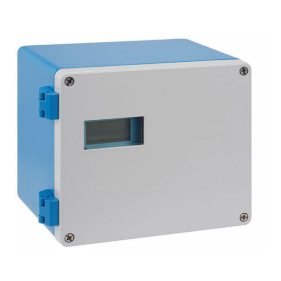
Product description Prosonic S FMU90 PROFIBUS DP Product description Product layout: polycarbonate field housing Valid for: Order code 030 (housing, material) Option 1 (PC field mounting, IP66 NEMA4x) A0035266 1 Parts of the Prosonic S in the polycarbonate field housing... -
Page 9: Product Layout: Din Rail Housing
Prosonic S FMU90 PROFIBUS DP Product description P ro > A0033256 2 Parts of the Prosonic S in the aluminum field housing Aluminum field housing, open Nameplate Terminal for potential equalization (protective ground) Display and operating module Aluminum field housing, closed... - Page 10 Product description Prosonic S FMU90 PROFIBUS DP A0035265 4 Parts of the Prosonic S with remote display and operating module DIN rail housing without display and operating module Remote display and operating module for mounting in a cabinet The cable (3m [9.8 ft]) is supplied One possible version of the DIN rail housing is illustrated in the graphic above.
-
Page 11: Incoming Acceptance And Product
• Do the data on the nameplate match the ordering information on the delivery note? • If required (see nameplate): are the Safety Instructions (XA) provided? If one of these conditions is not met, please contact your Endress+Hauser sales office. Product identification The following options are available for the identification of the measuring device: •... -
Page 12: Storage, Transport
Incoming acceptance and product identification Prosonic S FMU90 PROFIBUS DP Storage, transport • Pack the device so that it is protected against impact for storage and transportation. The original packaging provides optimum protection. • Permitted storage temperature: –40 to +60 °C (–40 to 140 °F) -
Page 13: Installation
Prosonic S FMU90 PROFIBUS DP Installation Installation Mounting the polycarbonate field housing Valid for: Order code 030 (housing, material) Option 1 (PC field mounting, IP66 NEMA4x) 5.1.1 Installation conditions Dimensions of polycarbonate field housing ø6.5 (0.26) ≥ ≥ 55 (2.17) 55 (2.17) - Page 14 Installation Prosonic S FMU90 PROFIBUS DP 5.1.2 Mounting the device Wall mounting • The housing bracket supplied can also be used as a drilling template. • Mount the housing bracket on a level surface so that it cannot become warped or bent.
-
Page 15: Mounting The Aluminum Field Housing
Prosonic S FMU90 PROFIBUS DP Installation Mounting the aluminum field housing Valid for: Order code 030 (housing, material) Option 3 (aluminum field mounting, IP66 NEMA4x) 5.2.1 Installation conditions Dimensions of the aluminum field housing 180 (7.09) 7 (0.28) 11 (0.43) ≥55 (2.17) -
Page 16: Mounting The Din Rail Housing
Installation Prosonic S FMU90 PROFIBUS DP 5.2.2 Mounting the device P ro O rd > A0033331 10 Wall-mounted aluminum field housing Mounting the DIN rail housing Valid for: Order code 030 (housing, material) Option 2 (DIN rail mounting PBT, IP20) WARNING The DIN rail housing meets protection class IP06. - Page 17 Prosonic S FMU90 PROFIBUS DP Installation 5.3.1 Installation conditions Dimensions Σ = 0 Σ = 1...3 EN 60715 EN 60715 TH 35x7.5/15 TH 35x7.5/15 (1.4x0.3/0.6) (1.4x0.3/0.6) Σ = 4 EN 60715 TH 35x7.5/15 (1.4x0.3/0.6) A0035915 11 Dimensions of Prosonic S with DIN rail housing; Σ: number of additional connection modules. Unit of...
-
Page 18: Installation Of The Remote Display And Operating Module
Installation Prosonic S FMU90 PROFIBUS DP 5.3.2 Mounting the device EN 60715 TH 35x7.5/15 (1.4x0.3/0.6) A0032559 12 Mounting/disassembling the DIN rail housing. Unit of measurement mm (in) Installation Disassembly Installation of the remote display and operating module Valid for:... - Page 19 Prosonic S FMU90 PROFIBUS DP Installation A0032562 14 Mounting in remote display of FMU860/861/862 Remote display of Prosonic S with adapter plate Opening of remote display of the FMU860/861/862 5.4.2 Mounting the device Scope of delivery • Display and operating module 96 x 96 mm (3.78 x 3.78 in) •...
-
Page 20: Mounting The Sensors
Installation Prosonic S FMU90 PROFIBUS DP Mounting the sensors Further information and the documentation currently available can be found on the Endress+Hauser website: www.endress.com → Downloads. Sensor documentation: • TI01469F (FDU90) • TI01470F (FDU91) • TI01471F (FDU91F) • TI01472F (FDU92) •... -
Page 21: Electrical Connection
Prosonic S FMU90 PROFIBUS DP Electrical connection Electrical connection Connection conditions 6.1.1 Cable specification • Conductor cross-section: 0.2 to 2.5 mm (26 to 14 AWG) • Wire sleeve cross-section: 0.25 to 2.5 mm (24 to 14 AWG) • Min. stripping length: 10 mm (0.39 in) Connecting the device 6.2.1... - Page 22 Electrical connection Prosonic S FMU90 PROFIBUS DP Cable entries Precut openings on the bottom of the housing for the following cable entries: • M20x1.5 (10 openings) • M16x1.5 (5 openings) • M25x1.5 (1 opening) Use a suitable tool to cut out the openings.
- Page 23 Prosonic S FMU90 PROFIBUS DP Electrical connection Access to terminal compartment A0034897 19 Access to terminal compartment: single DIN rail housing unit A0034898 20 Access to terminal compartment: several DIN rail housing units mounted side by side 6.2.4...
- Page 24 Electrical connection Prosonic S FMU90 PROFIBUS DP Terminal areas • Basic terminal area (A) Found on all device versions • Terminal area for additional inputs and outputs (B) Found on the following device versions: • FMU90 - *****2****** • FMU90 - *******2**** •...
- Page 25 Prosonic S FMU90 PROFIBUS DP Electrical connection Terminals for power supply (DC version) Terminal area A • Terminal 1: L+ (10.5 to 32 V • Terminal 2: L- • Terminal 3: potential equalization • Fuse: 2AT Terminals for relays Terminal area A...
-
Page 26: Special Connection Instructions
Electrical connection Prosonic S FMU90 PROFIBUS DP Terminals for temperature input Terminal area D Terminals 83, 84, 85: • Pt100 • Omnigrad S TR61 (Endress+ Hauser) Other elements on the terminal areas Terminal area A • Display Connection of the display or the remote display and operating module •... - Page 27 Prosonic S FMU90 PROFIBUS DP Electrical connection Sync Service Fuse Display HART 0/4…20mA FDU- Sensor Relay 90 … 253 VAC 10 5 … 32 VDC A0035934 22 Connection of the power supply in the polycarbonate field housing Terminal block in field housing for potential equalization Potential equalization;...
- Page 28 Electrical connection Prosonic S FMU90 PROFIBUS DP Sync Service Fuse Display HART 0/4…20mA FDU- Sensor Relay 90 … 253 VAC 10 5 … 32 VDC A0035933 23 Connection of the power supply in the aluminum field housing Potential equalization in aluminum field housing; wired on delivery...
- Page 29 • Signal attenuation: < 9 dB over the entire length of the cable segment • Shielding: copper braided shielding or braided shielding and foil shield Pre-terminated cables are available from Endress+Hauser. T-junction boxes It is recommended to connect the Prosonic S using T-junction boxes. Suitable junction boxes are available from Endress+Hauser. Endress+Hauser...
- Page 30 Electrical connection Prosonic S FMU90 PROFIBUS DP Spurs Information regarding spurs • The cable between the connector and the bus driver in the field device is known as a spur. • Total length of all spurs < 6.6 m (22 ft) at max. 1.5 Mbit/s.
- Page 31 Prosonic S FMU90 PROFIBUS DP Electrical connection Connection diagram for FDU9x → FMU90 FDU90/91/92 FDU90/91 ≤30 m (98 ft) BN BU ≤300 m (984 ft) YE BK RD YE BK RD 24 VDC FMU90/95 FMU90/95 FDU91F/93/95 FDU91F/93/95 ≤30 m (98 ft)
- Page 32 Electrical connection Prosonic S FMU90 PROFIBUS DP Valid for the following sensors • FDU91F • FDU93 • FDU95 These sensors are no longer available but can be connected to the Prosonic S in existing installations. • FDU96 • FDU83 • FDU84 •...
- Page 33 Prosonic S FMU90 PROFIBUS DP Electrical connection Sync Service Fuse Display HART 0/4…20mA FDU- Sensor Relay FDU91F/93/95/96 (FDU83/84/85/86) 90 … 253 VAC 10 5 … 32 VDC A0033333 27 Potential equalization of metallic sensors in aluminum field housing Potential equalization in the field housing; wired on delivery...
- Page 34 (18 to 14 AWG) • Resistance Max. 8 Ω per wire • Capacitance, wire to shield Max. 60 nF • Protective ground (for FDU91F/93/95) May not be within the shielding. Suitable connection cables are available from Endress+Hauser (→ 92). Endress+Hauser...
- Page 35 Prosonic S FMU90 PROFIBUS DP Electrical connection 6.3.5 Shortening the sensor cable NOTICE Damaged wires or no return conductor may cause malfunctions ‣ Do not damage the wires when removing the insulation. ‣ After shortening the cable, twist the shielding metal braiding and connect it to the "BK"...
- Page 36 Electrical connection Prosonic S FMU90 PROFIBUS DP Technical data for sensor heater • Supply voltage 24 V ±10 % • Residual ripple < 100 mV • Current consumption 250 mA per sensor Temperature compensation with sensor heater If the sensor heater is used, connect an external temperature sensor to correct the sound time-of-flight and assign this temperature sensor to the sensor.
- Page 37 Prosonic S FMU90 PROFIBUS DP Electrical connection WARNING Explosion Hazard ‣ Install the power supply unit outside the hazardous area. ‣ Use a cable that meets the requirements of the zone in which the aluminum field housing is installed. ‣...
- Page 38 Electrical connection Prosonic S FMU90 PROFIBUS DP FMU90 Sync Service Fuse Display HART 0/4…20mA FDU- Sensor Relay FDU90 FDU91 24 VDC A0032575 32 Connection of the sensor heater via a metal DIN rail in the cabinet External power supply unit...
- Page 39 Prosonic S FMU90 PROFIBUS DP Electrical connection Cable specification for synchronization • Max. length 10 m (33 ft) between the individual transmitters • Cross-section 2 x 0.75 to 2.5 mm (18 to 14 AWG) • Cable shield Required for cables > 1 m (3.3 ft); ground the shield.
- Page 40 Electrical connection Prosonic S FMU90 PROFIBUS DP FMU90 FMU90 FMU90 (24 V) (24 V) (24 V) 24 V A0034904 35 Connection of external switches Liquiphant connection Connection of external switches (passive) Connection of external switches (active) Inputs for external switches •...
- Page 41 Prosonic S FMU90 PROFIBUS DP Electrical connection 84 85 FMU90 Pt100 Pt100 A0034905 36 Connection of a Pt100 temperature sensor Pt100 with 3-wire connection Pt100 with 4-wire connection (one connector is not used) The use of a 2-wire connection is not permitted due to insufficient measuring accuracy.
- Page 42 Electrical connection Prosonic S FMU90 PROFIBUS DP Connection of the Omnigrad S TR61 temperature sensor in hazardous areas FMU90 83 84 FMU90 83 84 ↑↑ ↑↑ A0033403 38 Connection of the Omnigrad S TR61 in hazardous areas Temperature sensor in hazardous area...
- Page 43 Prosonic S FMU90 PROFIBUS DP Electrical connection Sync Service Fuse Display HART 0/4…20mA FDU- Sensor Relay A0034903 39 Connection of the remote display and operating module Pre-terminated connecting cable 3 m (9.8 ft) with display plug (supplied) Minimum diameter for cable entry 20 mm (0.79 in)
-
Page 44: Operating Options
Operating options Prosonic S FMU90 PROFIBUS DP Operating options Structure and function of the operating menu 7.1.1 Submenus and parameter sets Parameters that belong together are grouped into one parameter set in the operating menu. Each parameter set is identified by a five-digit code. -
Page 45: Access To The Operating Menu Via The Local Display
Prosonic S FMU90 PROFIBUS DP Operating options Access to the operating menu via the local display 7.2.1 Display and operating elements Elements of the display and operating module A0034921 Soft key symbols Keys Light emitting diodes to indicate the relay switching states... - Page 46 Operating options Prosonic S FMU90 PROFIBUS DP Scroll symbols Scroll list available Is displayed if the picklist contains more options than can be shown on the display. All the options in the list can be displayed by pressing repeatedly. Navigation in the envelope curve display (select the "Cyclic" display format) •...
- Page 47 Prosonic S FMU90 PROFIBUS DP Operating options • • Opens the list of errors which are currently detected. • If a warning is present, the symbol flashes. • If an alarm is present, the symbol is displayed permanently. • Displays the next page of measured values (only available if several pages of measured values have been defined;...
- Page 48 Operating options Prosonic S FMU90 PROFIBUS DP 7.2.2 Calling the operating menu from a standard screen (measured value display) • Left button ("Info") : shortcut menu Provides fast access to the most important parameters: • Daily counter • Tag marking •...
-
Page 49: System Integration
• www.endress.de → use the search function under "Downloads". • GSD library of the PROFIBUS User Organization (PNO): http://www.PROFIBUS.com • CD-ROM with all the GSD files for Endress+Hauser devices; Order No.: 50097200 Using the GSD files The GSD files must be loaded into a specific subdirectory of the PROFIBUS DP configuration software of the PLC. - Page 50 System integration Prosonic S FMU90 PROFIBUS DP Software addressing • Software addressing takes effect when DIP switch 8 on the PROFIBUS DP terminal area is set to "SW (on)" (factory setting). • The address can then be configured via an operating tool (e.g. "DeviceCare" or "FieldCare").
- Page 51 Prosonic S FMU90 PROFIBUS DP System integration 8.2.2 Bus termination A0038437 45 Bus termination on the device Termination not active Termination active ‣ For the last device on the bus: Switch all four terminating switches to "on" to activate the bus terminating resistor.
-
Page 52: Commissioning
Commissioning Prosonic S FMU90 PROFIBUS DP Commissioning Preparatory steps 9.1.1 Reset to factory settings NOTICE A reset may negatively impact the measurement. ‣ Perform a new basic setup after resetting the device. Using the reset function It is always advisable to reset the device if you want to use a device with an unknown history. -
Page 53: Configuring The Measuring Device
Prosonic S FMU90 PROFIBUS DP Commissioning Configuring the measuring device 9.3.1 Navigation to the menu "Basic setup" Operating mode: "Level+flow" or "Flow" Flow → Flow → Flow N → Basic setup Operating mode: "Flow+backwater detection" Flow → Flow 1 +backwater → Flow → Basic setup 9.3.2... - Page 54 Commissioning Prosonic S FMU90 PROFIBUS DP 9.3.3 Parameter set "Linearization" Purpose of linearization To calculate the flow Q from the measured upstream level h. Navigation Basic setup → Linearization Parameters • Type • "Flume/weir" option Select this option to use a pre-programmed linearization curve.
- Page 55 Prosonic S FMU90 PROFIBUS DP Commissioning 0,0000 0,0000 0,0000 0,0000 0,0000 0,0000 … 0,0000 0,0000 A0040752 Line number Column for level Column for flow 1. Press to navigate inside the table. 2. Press to navigate inside the column with the line numbers.
- Page 56 Commissioning Prosonic S FMU90 PROFIBUS DP 9.3.5 Parameter set "Empty calibration" A0035535 46 Empty calibration for flume Ultrasonic sensor Measured distance Upstream level Empty calibration: "Empty E" A0035536 47 Empty calibration for weirs Ultrasonic sensor Measured distance Upstream level Empty calibration: "Empty E"...
- Page 57 Prosonic S FMU90 PROFIBUS DP Commissioning Parameter • Flow N Displays the flow Q currently measured for verification purposes. • Level Displays the level h currently measured for verification purposes. • Distance Displays the distance D currently measured for verification purposes.
- Page 58 Commissioning Prosonic S FMU90 PROFIBUS DP 9.3.7 Parameter set "Check value" • This parameter set starts interference echo suppression (mapping). • To record all the interference echoes, perform mapping at the minimum level possible (ideally in an empty channel). • If it is not possible to empty the channel during commissioning, record preliminary mapping when the channel is partially filled.
- Page 59 Prosonic S FMU90 PROFIBUS DP Commissioning 9.3.8 Parameter set "Distance mapping" Navigation Basic setup → Check value → Distance mapping Parameters • Actual distance Displays the distance D currently measured between the sensor membrane and the surface of the liquid.
-
Page 60: Advanced Settings
Commissioning Prosonic S FMU90 PROFIBUS DP Advanced settings 9.4.1 Configuration of backwater or dirt detection General principles FMU90 A0035517 49 Backwater detection with two ultrasonic sensors Upstream sensor Upstream level Downstream sensor Downstream level Flow measurement can be compromised by backwater on the downstream side or by dirt within the flume. - Page 61 Prosonic S FMU90 PROFIBUS DP Commissioning 4. Configure the downstream sensor (backwater or dirt detection). Parameter set "Backwater sensor selection" Navigation Flow → Flow 1 +backwater → Backwater → Basic setup → Backw. sensor sel. Parameter • Input Assign the downstream sensor to the channel.
- Page 62 Commissioning Prosonic S FMU90 PROFIBUS DP Parameter set "Backwater check value" • This parameter set starts mapping (inference echo suppression) for the downstream sensor. • To record all the interference echoes, perform mapping at the minimum level possible (ideally in an empty channel).
- Page 63 Prosonic S FMU90 PROFIBUS DP Commissioning Parameter set "Backwater mapping" Navigation Flow → Flow 1 +backwater → Backwater → Basic setup → Backwater mapping Parameter • Actual distance Displays the distance D currently measured between the sensor membrane and the surface of the liquid.
- Page 64 Commissioning Prosonic S FMU90 PROFIBUS DP 9.4.2 Configuring simultaneous level and flow measurement with one sensor Q(l/s) L (m) Q (l/s) 1 2 3 m A0038435 51 Simultaneous level and flow measurement with one sensor Sensor Prosonic S transmitter...
- Page 65 Prosonic S FMU90 PROFIBUS DP Commissioning • Error handling • Actual value: the current flow value is used for counting • Hold: the counter uses the flow value that was present when the error occurred. • Stop: the counter is stopped.
- Page 66 Commissioning Prosonic S FMU90 PROFIBUS DP A0036767 55 "Type" = "alter.3x2 val.". Up to six values can be displayed. These values are spread over three pages with two values on each. These pages are displayed cyclically. Press in the main display screen to change to the next value immediately.
- Page 67 Prosonic S FMU90 PROFIBUS DP Commissioning 9.4.5 Configuring the limit value relay Limit type = "Standard" or "Tendency/speed" A0036325 56 Parameters for "Limit type" = "Standard" or "Tendency/speed" "Switch-on point" > "Switch-off point" "Switch-off point" > "Switch-on point" Switch-on point...
- Page 68 Commissioning Prosonic S FMU90 PROFIBUS DP Configuration of the limit relay 1. Navigate to the parameter set Relay/controls → Relay configurat. → Relay N 2. In the Function parameter, select the Limit option. The Function picklist is displayed. 3. Select the variable to which the limit value refers.
- Page 69 Prosonic S FMU90 PROFIBUS DP Commissioning A0036676 58 Configuration of a time pulse relay Pulse time Pulse width Relay energized Relay de-energized Navigation Relay/controls → Relay configurat. → Relay N Parameter • Select function Select the Time pulse option.
- Page 70 Commissioning Prosonic S FMU90 PROFIBUS DP • Stop counter Specify the upper flow limit for counting. Flows above this value are ignored during counting. • Invert Specify whether the switching direction of the relay should be inverted. (Factory setting: No).
- Page 71 Prosonic S FMU90 PROFIBUS DP Commissioning 9.4.12 Configuration of the cyclic data telegram • The general principles of cyclic data exchange between the measuring device and an automation system (e.g. PLC) are described in Operating Instructions BA00034S, "PROFIBUS DP/PA - Guidelines for planning and commissioning".
- Page 72 Commissioning Prosonic S FMU90 PROFIBUS DP Default configuration of the cyclic data telegram (1-channel version) Valid for FMU90 - *****1*** "Level" operating mode • AI 1 • Bytes 0 - 3: Level 1 (IEEE754); unit: m • Byte 4: Status level 1 •...
- Page 73 Prosonic S FMU90 PROFIBUS DP Commissioning • AI 6 • Bytes 25 - 28: Overflow totalizer 1 (IEEE754) • Byte 29: Status totalizer 1 • AI 7 • Bytes 30 - 33: Value daily counter 1 (IEEE754) • Byte 34: Status daily counter 1 •...
-
Page 74: Simulation
Commissioning Prosonic S FMU90 PROFIBUS DP • AI 8 • Bytes 35 - 38: Overflow totalizer 1 (IEEE754) • Byte 39: Status totalizer 1 • AI 9 • Bytes 40 - 43: Value totalizer 2 (IEEE754) • Byte 44: Status totalizer 2 •... -
Page 75: Protecting Settings From Unauthorized Access
Prosonic S FMU90 PROFIBUS DP Commissioning Parameter • Simulation Select the variable to be simulated (level or volume). • Sim. level value Only available if Simulation = Sim. level. Specify the level to be simulated. The calculated flow and the output signal follow this value. - Page 76 Commissioning Prosonic S FMU90 PROFIBUS DP 9.6.3 Hardware locking Sync Service Fuse Display A0038472 59 Hardware locking Unlocked Locked A write protection switch, which can be used to lock the device against parameter changes, is located on the basic terminal area in the terminal compartment. When the device is locked the symbol is shown on the display.
-
Page 77: Diagnostics And Troubleshooting
Prosonic S FMU90 PROFIBUS DP Diagnostics and troubleshooting Diagnostics and troubleshooting 10.1 General troubleshooting 10.1.1 Calibration error Measured value incorrect Check the Actual distance parameter. • The Actual distance is incorrect: • For measurements in a bypass or ultrasound guide pipe: Set the appropriate option in the LVL N appl. - Page 78 Diagnostics and troubleshooting Prosonic S FMU90 PROFIBUS DP 3. Select which type of curve is to be displayed: envelope curve, floating average curve (FAC), mapping curve. 4. Select the display format: single curve or cyclic. The envelope curve display now appears: A0036421 ...
- Page 79 Prosonic S FMU90 PROFIBUS DP Diagnostics and troubleshooting Envelope curve display in FieldCare/DeviceCare A0036420 1. Click F (functions) on the menu bar. 2. Select the sensor whose envelope curve is to be displayed. 3. To display a single curve, click the Read curve button.
-
Page 80: Overview Of Diagnostic Information
Diagnostics and troubleshooting Prosonic S FMU90 PROFIBUS DP 10.2 Overview of diagnostic information 10.2.1 Error signal Displaying errors that occur during commissioning or operation: • Local display: • Error symbol • Error code • Error description • Cyclic data telegram Status that is transmitted with the measured value. - Page 81 Prosonic S FMU90 PROFIBUS DP Diagnostics and troubleshooting • A 0x 231 Distance: BAD Temperature: GOOD • A 0x 281 Distance: BAD Temperature: BAD • W 0x 281 Distance: UNCERTAIN Temperature: UNCERTAIN • W 0x 501 Distance: BAD Temperature: BAD • A 0x 502 Distance: BAD Temperature: BAD • W 0x 521...
- Page 82 Diagnostics and troubleshooting Prosonic S FMU90 PROFIBUS DP Error in the Flow Block (FS) • W 0x 602 Flow: BAD • W 0x 603 Flow: BAD • A 0x 605 Flow: BAD • A 0x 606 Flow: BAD • W 0x 612 Flow: BAD • W 0x 613 Flow: BAD • W 0x 803 Flow: UNCERTAIN •...
- Page 83 Checksum error → Total reset and recalibration • A 00 111/112/114/115 Electronics defect • → Switch off device and switch it on again. • → If the error persists: call Endress+Hauser Service. • A 00 116 Download error → Repeat download. • A 00 117 Hardware after change not identified •...
- Page 84 Diagnostics and troubleshooting Prosonic S FMU90 PROFIBUS DP • A 00 250 Faulty external temperature sensor → Check temperature sensor. • A 0x 281 Temperature readings sensor 01 or 02 defect - check connection → Check that the sensor is connected correctly. • W 0x 501 No sensor selected for input 01 or 02 →...
-
Page 85: Firmware History
Prosonic S FMU90 PROFIBUS DP Diagnostics and troubleshooting • W 0x 70y Operating hours alarm pump y PST x → Reset operating hours (Op.hour alarm submenu). • W 0x 71y Failure pump y PST x → Check pump 1. After rectifying the pump error, reset the pump controller or switch the device off and on again. -
Page 86: Maintenance
Maintenance Prosonic S FMU90 PROFIBUS DP Maintenance No special maintenance work is required. 11.1 Exterior cleaning When cleaning the exterior, always use cleaning agents that do not corrode the surface of the housing and the seals. Endress+Hauser... -
Page 87: Repair
Endress+Hauser sales representative. 12.1.2 Repair of Ex-certified devices • Only specialist personnel or Endress+Hauser-Service can carry out repairs to Ex certified devices. • Comply with the prevailing standards, national Ex-area regulations, Safety Instructions (XA) and certificates. -
Page 88: Disposal
Repair Prosonic S FMU90 PROFIBUS DP 2. Return the device if repairs or a factory calibration are required, or if the wrong device was ordered or delivered. 12.4 Disposal Observe the following notes during disposal: • Observe valid federal/national regulations. -
Page 89: Accessories
Accessories Accessories 13.1 Communication-specific accessories 13.1.1 Commubox FXA291 • Connects the CDI interface (Common Data Interface) of Endress+Hauser devices with the USB port of a computer. • Order number: 51516983 • Additional information: Technical Information TI00405C 13.2 Device-specific accessories 13.2.1... - Page 90 Accessories Prosonic S FMU90 PROFIBUS DP 13.2.2 Mounting plate for polycarbonate field housing A0034923 62 Mounting plate for polycarbonate field housing • Compatible with the Prosonic S housing bracket • Pipe diameter: 25 to 50 mm (1 to 2 in) •...
- Page 91 Prosonic S FMU90 PROFIBUS DP Accessories Material 316L (1.4404) Order number 71452327 Frame, 1 400 mm (55.1 in) 3.2 (0.13) 60 (2.36) ø33.7 (1.3) 4 (0.16) 20 (0.8) 55 (2.17) 109 (4.29) (3.94) 130 (5.12) 150 (5.91) A0037800 64 Dimensions.
- Page 92 Accessories Prosonic S FMU90 PROFIBUS DP 13.2.3 Adapter plate for remote display A0035916 65 Use of adapter plate Remote display of Prosonic S FMU9x with adapter plate Installation opening of the remote display of the FMU86x predecessor transmitter To mount the remote display of the Prosonic S FMU9x in the housing of the larger remote display of the FMU86x predecessor •...
- Page 93 Prosonic S FMU90 PROFIBUS DP Accessories FDU95 • Cable type: Li2G2G 2x(0.75)D+1x0.75 • Material: silicone • Ambient temperature:–40 to +150 °C (–40 to +302 °F) • Order number: 71027745 13.2.6 Temperature sensor Omnigrad S TR61 125 (4.92) 28 (1.1) 78 (3.01) A0035035 ...
-
Page 94: Operating Menu
Operating menu Prosonic S FMU90 PROFIBUS DP Operating menu 14.1 Menu "Level → Level (LVL N)" 14.1.1 Submenu "Basic setup" Parameter set L1003 "LVL N sensor sel." • Input • Sensor selection • Detected Parameter set L1004 "LVL N appl. param."... -
Page 95: Menu "Flow N
Prosonic S FMU90 PROFIBUS DP Operating menu Parameter set L1017 "LVL N check value" Correction Parameter set L1018 "LVL N correction" Offset Parameter set L1020 "LVL N blocking distance" Blocking distance Parameter set L1019 "LVL N limitation" • Limitation • Upper limit •... - Page 96 Operating menu Prosonic S FMU90 PROFIBUS DP Parameter set F1005 "Flow N" • Flow N • Level • Distance Parameter set F1006 "Flow N check value" • Distance • Check distance Parameter set F1008 "Flow N mapping" • Distance • Range of mapping •...
-
Page 97: Menu "Backwater
Prosonic S FMU90 PROFIBUS DP Operating menu 14.3 Menu "Backwater" Navigation to the submenu Flow → Flow 1+ backw. → Backwater 14.3.1 Submenu "Basic setup" Parameter set F1304 "Backwater sensor selection" • Input • Sensor selection • Detected Parameter set F1305 "Backw. empty cal."... -
Page 98: Menu "Flow Counter
Operating menu Prosonic S FMU90 PROFIBUS DP 14.3.3 Submenu "Simulation" Parameter set F1600 "Backw. simulation" • Simulation • Sim. level value 14.4 Menu "Flow counter" Navigation to the submenu: Flow → Flow counter 14.4.1 Submenu "Totalizer" Parameter set F1202 "Totalizer N"... -
Page 99: Menu "Relay/Controls
Prosonic S FMU90 PROFIBUS DP Operating menu Parameter set AX105 "In safety dist." • In saf. dist.s N • Reset sen N Parameter set AX107 "React. high temp." • Overtemp. sen. N • Max. temp. sen. N Parameter set A0000 "Defect temp. sen."... - Page 100 Operating menu Prosonic S FMU90 PROFIBUS DP Parameter set R13A3 "Pump control N" • Switch-on point • Switch-off point • Min. pump rate/min • Crust reduction • Switch on border • Hook up interval • Alternate Parameter set R13A2 "Pump control N"...
- Page 101 Prosonic S FMU90 PROFIBUS DP Operating menu Parameter set R1408 "Relay allocation → Relay K" • Function • Invert 14.6.4 Submenu "Pump control N → Basic setup" (extended - pump rate control) Valid for: • FMU90-*3********** • FMU90-*4********** Navigation to the submenu: Relay/controls →...
- Page 102 Operating menu Prosonic S FMU90 PROFIBUS DP Parameter set R1601 "Storm function N" • Storm function • Switch-on point • Switch-off point • Storm time 14.6.6 Submenu "Pump control N → Function test" Valid for: • FMU90-*3********** • FMU90-*4********** Navigation to the submenu: Relay/controls →...
- Page 103 Prosonic S FMU90 PROFIBUS DP Operating menu 14.6.9 Submenu "Pump control N → Pump data" Valid for: • FMU90-*3********** • FMU90-*4********** Navigation to the submenu: Relay/controls → Pump control N → Pump data → Pump M Parameter set R1611 "Pump dat. P M"...
- Page 104 Operating menu Prosonic S FMU90 PROFIBUS DP 14.6.12 Submenu "Rake control" Parameter set R1200 "Rake control" • Upstream water • Downstream water • Function Parameter set R1201 "Rake control" • Switch-on point • Switch-off point Parameter set R1202 "Rake control"...
-
Page 105: Overview Of The "Output/Calculat." Menu
Prosonic S FMU90 PROFIBUS DP Operating menu Parameter set R1204 "Relay N" • Invert • Failure mode 14.6.16 Submenu "Relay configurat. → Relay N" (function: alarm/ diagnost.) Parameter set R2103 "Relay N" • Function → Alarm/diagnost. • Alarm relay • Diagnostics •... -
Page 106: Overview Of The "Device Properties" Menu
Operating menu Prosonic S FMU90 PROFIBUS DP 14.8 Overview of the "Device properties" menu 14.8.1 Submenu "Operating param." Parameter set D1101 "Distance unit" Distance unit Parameter set D110B "Temperature unit" Temperature unit Parameter set D110C "Operating mode" Operating mode Parameter set D110D "Controls"... - Page 107 Prosonic S FMU90 PROFIBUS DP Operating menu 14.9.2 Submenu "In/output info" Parameter set IX108 "Level N" • Input • Sensor selection • Detected Parameter set IX109 "Flow N" • Input • Sensor selection • Detected Parameter set IX10B "Relay N"...
-
Page 108: 14.10 Menu "Display
Operating menu Prosonic S FMU90 PROFIBUS DP Parameter set E1405 "Act. meas. value" • Level N • Flow N Parameter set E1405 "Application par." Sensor N Parameter set E1406 "Echo quality sen." Echo quality N 14.10 Menu "Display" Parameter set DX202 "Display"... - Page 109 Prosonic S FMU90 PROFIBUS DP Operating menu Parameter set D1022 "Ext. temp. sensor" • Failure mode • Value at warning 14.11.3 Submenu "Sensor management → FDU sensor → External digin" Parameter set D1025 "Ext. digin N" • Invert • Value...
- Page 110 *71526730* 71526730 www.addresses.endress.com...