
Related Manuals for Extreme Networks ExtremeSwitching VDX 6740


Summary of Contents for Extreme Networks ExtremeSwitching VDX 6740
- Page 1 HARDWARE INSTALLATION GUIDE ExtremeSwitching VDX 6740 Hardware Installation Guide 9036108-00 April 2019...
- Page 2 Legal Notice Extreme Networks, Inc. reserves the right to make changes in specifications and other information contained in this document and its website without prior notice. The reader should in all cases consult representatives of Extreme Networks to determine whether any such changes have been made.
-
Page 3: Table Of Contents
Installing the device in the rack........................................ 33 Attaching the rear brackets to the front brackets................................34 Attaching the rear brackets to the rack rails..................................35 Installing the 1U, 1.5U, and 2U Universal Kit for Four Post Racks (XBR-R000295)....................35 ExtremeSwitching VDX 6740 Hardware Installation Guide 9036108-00... - Page 4 Connecting a DC power cord to a 250W DC power supply............................88 Verifying operation..............................................89 Establishing a serial connection........................................89 Assigning permanent passwords ........................................90 Changing the default account passwords ..................................90 Configuring the device IP address........................................91 ExtremeSwitching VDX 6740 Hardware Installation Guide 9036108-00...
- Page 5 Replacing a 500W AC power supply....................................113 Determining the need to replace a fan assembly................................115 Time and items required to replace a fan assembly..............................115 Replacing a fan assembly........................................115 Technical Specifications....................................... 117 ExtremeSwitching VDX 6740 Switch Technical Specifications............................117 ExtremeSwitching VDX 6740 Hardware Installation Guide 9036108-00...
- Page 6 Japan power cord ..............................................127 Cautions and Danger Notices..................................... 129 Cautions................................................... 129 General cautions............................................129 Electrical cautions............................................131 Danger Notices..............................................133 General dangers............................................134 Electrical dangers............................................134 Dangers related to equipment weight....................................134 Laser dangers.............................................. 135 ExtremeSwitching VDX 6740 Hardware Installation Guide 9036108-00...
-
Page 7: Preface
Getting Help..........................................8 • Providing Feedback to Us....................................9 ® This section discusses the conventions used in this guide, ways to provide feedback, additional help, and other Extreme Networks publications. Conventions This section discusses the conventions used in this guide. Notes, cautions, and warnings Notes, cautions, and warning statements may be used in this document. -
Page 8: Command Syntax Conventions
Training Extreme Networks offers product training courses, both online and in person, as well as specialized certifications. For more information, visit www.extremenetworks.com/education/. Getting Help If you require assistance, contact Extreme Networks using one of the following methods:... -
Page 9: Subscribing To Service Notifications
Providing Feedback to Us Quality is our first concern at Extreme Networks, and we have made every effort to ensure the accuracy and completeness of this document. We are always striving to improve our documentation and help you work better, so we want to hear from you! We welcome all feedback but especially want to know about: •... - Page 10 ExtremeSwitching VDX 6740 Hardware Installation Guide 9036108-00...
-
Page 11: About This Document
What’s new in this document..................................11 Supported hardware and software This document includes information specific to the ExtremeSwitching VDX 6740 and ExtremeSwitching VDX 6740T running Extreme Network OS version 7.1.0 and later. The VDX 6740T information in this guide also covers the VDX 6740T-1G variant running Extreme Network OS version 7.1.0 and later. - Page 12 ExtremeSwitching VDX 6740 Hardware Installation Guide 9036108-00...
-
Page 13: Product Overview
Product features......................................... 13 • Hardware components....................................18 Product features The ExtremeSwitching VDX 6740 product family includes three top-of-rack, Gigabit Ethernet (GbE) line-rate, low latency, lossless Data Center Bridging (DCB) devices: The VDX 6740 has the following features: • Base models support 24 Ethernet ports. A 10G Port Upgrade license can add ports in increments of 8, 16, and 24 ports, for a total of 48 Ethernet ports. -
Page 14: Flexport
However, if the FlexPort is configured as FC port, it won't become an ISL port. For details on the FlexPort feature, including port ranges on VDX 6740 models that can be configured as FlexPorts, connector groups, and configuration procedures, refer to the Network OS Management Configuration Guide. ExtremeSwitching VDX 6740 Hardware Installation Guide 9036108-00... -
Page 15: Using The Vdx 6740T As A Dhcp Server
Using the VDX 6740T as a DHCP server You can connect the VDX 6740T to the management port on any Extreme Networks switch (DHCP client) and use the VDX 6740T as a DHCP server to support DHCP Automatic Deployment (DAD), DHCP zero touch provisioning (ZTP), obtaining switch IP addresses, and other services. -
Page 16: Extreme Networks Inter-Switch Link Trunks
Extreme Networks inter-switch link trunks In VCS mode, unless specifically disabled, inter-switch link (ISL) Extreme Networks trunking between adjacent devices is automatic. All ports must be in the same port group and must be configured at the same speed. There is a limit of sixteen ports per trunk group. No separate licensing is required. -
Page 17: Supported Transceivers
Extreme Networks inter-switch link trunks In VCS mode, unless specifically disabled, inter-switch link (ISL) Extreme Networks trunking between adjacent devices is automatic. All ports must be in the same port group and must be configured at the same speed. There is a limit of sixteen ports per trunk group. No separate licensing is required. -
Page 18: Hardware Components
Up to 48 1/10G Base-T copper ports. These ports support 100 Mbps operation (Network OS v4.1.0 and later). Note that forty-eight 1G Base-T copper ports are supported on the VDX 6740T-1G variant, which can be upgraded to 1/10G operation through 10G Port Upgrade licensing. ExtremeSwitching VDX 6740 Hardware Installation Guide 9036108-00... -
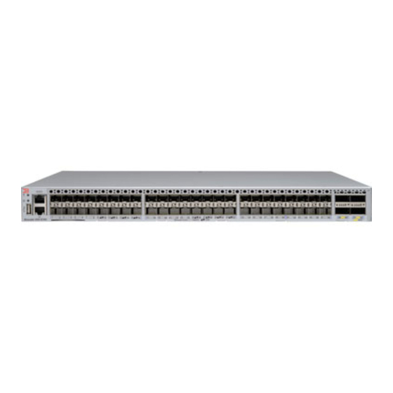
Page 19: Port Side View
A USB port for firmware upgrades and system log downloads – Support for inter-switch link (ISL) Extreme Networks Trunking (10, 40, and 100 GbE ports only) – Extensive diagnostics and system-monitoring capabilities for enhanced high Reliability, Availability, and Serviceability (RAS) –... -
Page 20: Nonport Side View
**FlexPort allows configuration of specific VDX 6740T 40 GbE QSFP+ ports as 1/10 GbE or 4, 8, or 16 Gbps FC ports. Nonport side view The following illustration shows the non-port side of the VDX 6740, which contains the combined power supply and fan assemblies. ExtremeSwitching VDX 6740 Hardware Installation Guide 9036108-00... - Page 21 The following illustration shows the non-port side of the VDX 6740T, which house the separate power supplies and fans. NOTE The un-numbered features on the DC power supply are identical to the features on the AC power supply. ExtremeSwitching VDX 6740 Hardware Installation Guide 9036108-00...
-
Page 22: Extreme Networks Inter-Switch Link Trunks
Extreme Networks inter-switch link trunks In VCS mode, unless specifically disabled, inter-switch link (ISL) Extreme Networks trunking between adjacent devices is automatic. All ports must be in the same port group and must be configured at the same speed. There is a limit of sixteen ports per trunk group. No separate licensing is required. - Page 23 For the VDX 6740T-1G variant, if you release Dynamic Ports On Demand (DPOD) licenses from any 10GbE ports on a 16-port trunk configured with static 10G speed, reserve back those licenses, then enable the shutdown and no shutdown commands on all trunk ports, the trunk bandwidth will not restore to the maximum 160 Gbps. ExtremeSwitching VDX 6740 Hardware Installation Guide 9036108-00...
- Page 24 ExtremeSwitching VDX 6740 Hardware Installation Guide 9036108-00...
-
Page 25: Preparing For The Installation
Installation and safety considerations You can install the devices in the following ways: • As a standalone unit on a flat surface. • For the ExtremeSwitching VDX 6740 device: – In a four-post EIA rack. – In a two-post telecommunications (Telco) rack. -
Page 26: Environmental Precautions
Cables can be organized and managed in a variety of ways; for example, use cable channels on the sides of the EIA rack or patch panels to reduce the potential for tangling the cables. The following list provides some recommendations for cable management: ExtremeSwitching VDX 6740 Hardware Installation Guide 9036108-00... -
Page 27: Items Required For The Installation
(Optional) Access to an FTP server or Extreme-branded USB device for backing up the device configuration. • (Optional) If mounting in the iDataplex IBM 15.5-inch depth rack, the Extreme Networks iDataplex rack mount kit. Items included with the device The following items are included with the standard shipment of a fully-configured VDX 6740. When you open the packaging, verify that the items are included in the package and that no damage has occurred during shipping. - Page 28 ExtremeSwitching VDX 6740 Hardware Installation Guide 9036108-00...
-
Page 29: Mounting The Device
Installing the Universal Two-Post Rack Kit (XBR-R000294)......................74 Mounting options You can mount the ExtremeSwitching VDX 6740 device in the following locations: • As a standalone unit on a flat surface, for example, a table top. Use the rubber feet included with the shipment to secure the device on the surface. -
Page 30: Mounting Precautions
Provide power to the device as described under "Providing power to the device." NOTE Do not connect the device to the network until the IP address is correctly set. For instructions on how to set the IP address, refer to "Configuring the device IP address." ExtremeSwitching VDX 6740 Hardware Installation Guide 9036108-00... -
Page 31: Installing The 1U Slim Rail Rack Mount Kit For Four-Post Racks (Xbr-000291)
The device must be turned off and disconnected from the fabric during this procedure. Parts List The following parts are provided with the 1U Slim Rail Rack Mount Kit for Four-Post Racks (XBR-000291). ExtremeSwitching VDX 6740 Hardware Installation Guide 9036108-00... -
Page 32: Attaching The Front Brackets
Not all parts may be used with certain installations depending on the device type. CAUTION Use the screws specified in the procedure. Using longer screws can damage the device. Attaching the front brackets Complete the following steps to attach the front brackets to the device. ExtremeSwitching VDX 6740 Hardware Installation Guide 9036108-00... -
Page 33: Installing The Device In The Rack
Do not attempt to mount the device with standard rail kits. • ExtremeSwtiching 6510 • ExtremeSwtiching 6505 • ExtremeSwtiching VDX 6740 ExtremeSwitching VDX 6740 Hardware Installation Guide 9036108-00... -
Page 34: Attaching The Rear Brackets To The Front Brackets
Position the right rear bracket inside the right front bracket as shown in the following figure. Attach the brackets using four 6-32 x 1/4 in. screws. Adjust the brackets to rack depth and tighten the screws to a torque of 9 in-lb (10 cm-kg). ExtremeSwitching VDX 6740 Hardware Installation Guide 9036108-00... -
Page 35: Attaching The Rear Brackets To The Rack Rails
The device can be installed so that the port side is either flush with the front posts or recessed with the non-port side flush with the rear posts. A recessed position allows a more gradual bend in the fiber-optic cables connected to the device and less interference in the aisle at the front of the rack. ExtremeSwitching VDX 6740 Hardware Installation Guide 9036108-00... -
Page 36: Time And Items Required
The following items are required to install the device using the 1U, 1.5U, and 2U Universal Kit for Four-Post Racks: • #2 Phillips torque screwdriver • 1/4-inch slotted-blade torque screwdriver Parts list The following parts are provided with the 1U, 1.5U, and 2U Universal Kit for Four Post Racks Installation (XBR-R000295). ExtremeSwitching VDX 6740 Hardware Installation Guide 9036108-00... -
Page 37: Flush-Front Mounting The Device In The Rack
Use the screws specified in the procedure. Using longer screws can damage the device. Flush-front mounting the device in the rack CAUTION The device must be turned off and disconnected from the fabric during this procedure. ExtremeSwitching VDX 6740 Hardware Installation Guide 9036108-00... -
Page 38: Attaching The Front Brackets
Use the upper and lower screw holes, leaving the center holes empty. Repeat Step 1 and Step 2 to attach the left front bracket to the left side of the device. ExtremeSwitching VDX 6740 Hardware Installation Guide 9036108-00... -
Page 39: Attaching The Bracket Extensions To The Device
Use the upper and lower screw holes, leaving the center holes empty. Repeat step 1 and step 2 to attach the left bracket extension to the left side of the device. ExtremeSwitching VDX 6740 Hardware Installation Guide 9036108-00... -
Page 40: Installing The Device In The Rack
Attach the left front bracket to the left front rack post using two 10-32 x 5/8-in. panhead screws and two retainer nuts. Use the upper and lower holes in the bracket. ExtremeSwitching VDX 6740 Hardware Installation Guide 9036108-00... -
Page 41: Attaching The Rear Brackets To The Extensions
Attach the brackets using four 6-32 x 1/4-in. panhead screws. Repeat Step 2 Step 3 to attach the left rear bracket to the left extension. ExtremeSwitching VDX 6740 Hardware Installation Guide 9036108-00... - Page 42 Adjust the brackets to the rack depth and tighten all the 6-32 x 1/4-in. screws to a torque of 9 in-lb (10 cm-kg). FIGURE 22 Attaching the short rear brackets to the extensions Rear brackets Screws, 6-32 x 1/4-in., panhead Phillips FIGURE 23 Attaching the medium or long rear brackets to the extensions ExtremeSwitching VDX 6740 Hardware Installation Guide 9036108-00...
-
Page 43: Attaching The Rear Brackets To The Rack Posts
Tighten all the 10-32 x 5/8-in. screws to a torque of 25 in-lb (29 cm-kg). FIGURE 24 Attaching the rear brackets to the rack posts Screws, 10-32 x 5/8-in., panhead Phillips Retainer nuts, 10-32 ExtremeSwitching VDX 6740 Hardware Installation Guide 9036108-00... -
Page 44: Flush-Rear (Recessed) Mounting The Device In The Rack
Use the upper and lower screw holes, leaving the center holes empty. Repeat Step 1 Step 2 to attach the left front bracket to the left rear side of the device. ExtremeSwitching VDX 6740 Hardware Installation Guide 9036108-00... -
Page 45: Attaching The Bracket Extensions To The Front Of The Device
Use the upper and lower screw holes, leaving the center holes empty. Repeat step 1 and step 2 to attach the left front bracket extension to the left side of the device. ExtremeSwitching VDX 6740 Hardware Installation Guide 9036108-00... -
Page 46: Installing The Device In The Rack
Attach the left front bracket to the left rear rack post using two 10-32 x 5/8-in. panhead screws and two retainer nuts. Use the upper and lower holes in the bracket. ExtremeSwitching VDX 6740 Hardware Installation Guide 9036108-00... -
Page 47: Attaching The Rear Brackets To The Bracket Extensions At The Front Of The Device
Attach the brackets using four 6-32 x 1/4-in. panhead screws. Repeat Step 2 Step 3 to attach the left rear bracket to the left extension. ExtremeSwitching VDX 6740 Hardware Installation Guide 9036108-00... - Page 48 Adjust the brackets to the rack depth and tighten all the 6-32 x 1/4-in. screws to a torque of 9 in-lb (10 cm-kg). FIGURE 28 Attaching the short rear brackets to the extensions at the front of the device Rear brackets, short Screws, 6-32 x 1/4-in., panhead Phillips ExtremeSwitching VDX 6740 Hardware Installation Guide 9036108-00...
-
Page 49: Attaching The Rear Brackets To The Front Rack Posts
30. Use the upper and lower holes in the bracket. Attach the left rear bracket to the left front rack post using two 10-32 x 5/8-in. screws and two retainer nuts. Use the upper and lower holes in the bracket. ExtremeSwitching VDX 6740 Hardware Installation Guide 9036108-00... -
Page 50: Installing The 1U, 1.5U, And 2U Mid-Mount Kit For Two-Post Racks (Xbr-000165, Xbr-000175, And Xbr-R000292)
Two people are required to install the device in a rack. One person holds the device, while the other secures the device to the rack. • Before mounting your device, review any specific installation and facility requirements in this Hardware Installation Guide. ExtremeSwitching VDX 6740 Hardware Installation Guide 9036108-00... -
Page 51: Time And Items Required
The following parts are provided with the 1U, 1.5U, or 2U Mid-Mount Rack Kit for Two-Post Racks (XBR-000165, XBR-000175, and XBR-R000292). NOTE Depending on the device type, not all parts may be used in an installation. ExtremeSwitching VDX 6740 Hardware Installation Guide 9036108-00... -
Page 52: Attaching The Front Brackets To The Device
To install the device in a recessed position in the rack, use the bracket holes that are set back from the end of the bracket. Insert 8-32 x 5/16-in. screws through the rest of the holes in the bracket and into the corresponding holes in the device. ExtremeSwitching VDX 6740 Hardware Installation Guide 9036108-00... -
Page 53: Attaching The Device To A Rack
Attach the right front bracket to the right rack rail using three 10-32 x 5/8-in. screws and three 10-32 retainer nuts. Attach the left front bracket to the left rack rail using three 10-32 x 5/8-in. screws and three 10-32 retainer nuts. ExtremeSwitching VDX 6740 Hardware Installation Guide 9036108-00... -
Page 54: Attaching The Rear Brackets To The Rack
Attaching the rear brackets to the rack NOTE Do not use the rear brackets for the Extreme Networks 6505, 6510, or 6520 switches. Complete the following steps to attach the rear brackets to the rack. Position the right rear bracket in the right rear of the device as shown in the following figure. -
Page 55: Attaching The Rear Brackets To The Device
Align the left rear bracket to the left rear of the device and use two 8-32 x 5/16-in. screws to attach the bracket to the device as shown in the following figure. ExtremeSwitching VDX 6740 Hardware Installation Guide 9036108-00... -
Page 56: Installing The 1U And 2U Flush-Mount Rack Kit For Two-Post Racks (Xbr-000307 And Xbr-R000293)
The following items are required to install a device using the 1U and 2U Flush-Mount Rack Kit for Two-Post Racks (XBR-000307 and XBR-R000293). • Phillips #2 torque screwdriver • 1/4-inch slotted blade torque screwdriver ExtremeSwitching VDX 6740 Hardware Installation Guide 9036108-00... -
Page 57: Parts List
FIGURE 36 Rack kit parts Front brackets, right and left (2) Screw, 10-32 x 5/8-in., panhead Phillips (8) Rear brackets, right and left (2) Retainer nut, 10-32 (8) Screw, 8-32 x 5/16-in., panhead Phillips (12) ExtremeSwitching VDX 6740 Hardware Installation Guide 9036108-00... -
Page 58: Attaching The Front Brackets To The Device
Repeat step 1 through step 3 to attach the left front bracket to the left side of the device. Tighten all 8-32 x 5/16-in. screws to a torque of 15 in-lbs. (17 cm-kgs). FIGURE 37 Attaching the front brackets Front brackets, right and left Screw, 8-32 x 5/16-in., panhead Phillips ExtremeSwitching VDX 6740 Hardware Installation Guide 9036108-00... -
Page 59: Attaching The Front Brackets To The Rack
Attach the brackets to the right rack upright using three 10-32 x 5/8-in. screws and retainer nuts. Repeat step 1 and step 2 to attach the left rear bracket to the left rack upright. ExtremeSwitching VDX 6740 Hardware Installation Guide 9036108-00... -
Page 60: Attaching The Rear Brackets To The Device
Align the right rear bracket to the right rear of the device and using two 8-32 x 5/16-in. screws, attach the bracket to the device as shown in the following figure. Align the left rear bracket to the left rear of the device and using two 8-32 x 5/16-in. screws, attach the bracket to the device. ExtremeSwitching VDX 6740 Hardware Installation Guide 9036108-00... -
Page 61: Installing The Universal Four-Post Rack Kit (Xbr-R000296)
The maximum rack depth for a chassis less than 40.64 cm (16 in.) is 81.28 cm (32 in.) minus the difference between the chassis depth and 40.64 cm (16 in.). For example, a chassis with a depth (L) of 35.56 cm (14 in.) is 5.08 cm (2 ExtremeSwitching VDX 6740 Hardware Installation Guide 9036108-00... -
Page 62: Time And Items Required
The following items are required to install the device using the Universal Four-Post Rack Kit: • #2 Phillips torque screwdriver • 1/4-inch slotted-blade torque screwdriver Parts list The following parts are provided wit the 1U, 1.5U, and 2U Universal Kit for Four Post Racks Installation (XBR-R000296). ExtremeSwitching VDX 6740 Hardware Installation Guide 9036108-00... - Page 63 Ensure that the items listed and illustrated are included in the kit. Note that not all parts may be used with certain installations depending on the device type. CAUTION Use the screws specified in the procedure. Using longer screws can damage the device. ExtremeSwitching VDX 6740 Hardware Installation Guide 9036108-00...
-
Page 64: Flush-Front Mounting
Use the upper and lower screw holes, leaving the center holes empty. Repeat step 1 and step 2 to attach the left front bracket to the left side of the device. ExtremeSwitching VDX 6740 Hardware Installation Guide 9036108-00... - Page 65 Use the upper and lower screw holes, leaving the center holes empty. Repeat step 2 and step 3 to attach the left bracket extension to the left side of the device. ExtremeSwitching VDX 6740 Hardware Installation Guide 9036108-00...
- Page 66 Attach the left front bracket to the left front rack post using two 10-32 x 5/8-in. panhead screws and two retainer nuts. Use the upper and lower holes in the bracket. ExtremeSwitching VDX 6740 Hardware Installation Guide 9036108-00...
- Page 67 If possible, leave at least one empty vertical pair of holes between the screws for better support. Repeat step 2 and 3 to attach the left rear bracket to the left bracket extension. ExtremeSwitching VDX 6740 Hardware Installation Guide 9036108-00...
- Page 68 46. Use the upper and lower holes in the bracket. Attach the left rear bracket to the left rear rack post using two 10-32 x 5/8-in. panhead screws and two retainer nuts. Use the upper and lower holes in the bracket. ExtremeSwitching VDX 6740 Hardware Installation Guide 9036108-00...
-
Page 69: Flush-Rear (Recessed) Mounting
Installing the device in the rack on page 71 Attaching the rear brackets to the extensions at the front of the device on page 72 Attaching the rear brackets to the front rack posts on page 74 ExtremeSwitching VDX 6740 Hardware Installation Guide 9036108-00... - Page 70 Insert four 8-32 x 5/16-in. flathead screws through the vertically aligned holes in the bracket extension and then into the holes on the side of the device. Use the upper and lower screw holes, leaving the center holes empty. ExtremeSwitching VDX 6740 Hardware Installation Guide 9036108-00...
- Page 71 Attach the left front bracket to the left rear rack post using two 10-32 x 5/8-in. panhead screws and two retainer nuts. Use the upper and lower holes in the bracket. ExtremeSwitching VDX 6740 Hardware Installation Guide 9036108-00...
- Page 72 Attach the brackets using four 6-32 x 1/4-in. panhead screws. Repeat step 2 and step 3 to attach the left rear bracket to the left extension. ExtremeSwitching VDX 6740 Hardware Installation Guide 9036108-00...
- Page 73 FIGURE 50 Attaching the rear brackets to the extensions at the front of the device Rear brackets, short Screws, 6-32 x 1/4-in., panhead Phillips FIGURE 51 Attaching the short or long rear brackets to the extensions ExtremeSwitching VDX 6740 Hardware Installation Guide 9036108-00...
-
Page 74: Installing The Universal Two-Post Rack Kit (Xbr-R000294)
Installing the Universal Two-Post Rack Kit (XBR- R000294) Use the following instructions to install an Extreme Networks 1U or 2U device in a two-post telecommunications (Telco) rack using the Universal Two-Post Rack Kit (XBR-R000294). There are two ways you can mount the device in a two-post rack: •... -
Page 75: Time And Items Required
The following items are required to install the device using the Universal Two-Post Rack Kit: • #2 Phillips torque screwdriver • 1/4-inch slotted-blade torque screwdriver Parts list The following parts are provided with the Universal Two-Post Rack Kit Installation (XBR-R000294). ExtremeSwitching VDX 6740 Hardware Installation Guide 9036108-00... -
Page 76: Flush-Front Mounting
Use the screws specified in the procedure. Using longer screws can damage the device. Complete the following tasks to install the device in a rack: Attaching the front brackets to the device on page 77 Attaching the front brackets to the rack on page 77 ExtremeSwitching VDX 6740 Hardware Installation Guide 9036108-00... - Page 77 Attach the right front bracket to the right rack upright using two 10-32 x 5/8-in. panhead screws and two retainer nuts. Use the upper and lower holes in the bracket. ExtremeSwitching VDX 6740 Hardware Installation Guide 9036108-00...
- Page 78 Attach the bracket to the right rack upright using two 10-32 x 5/8-in. panhead screws and two retainer nuts. Use the upper and lower holes in the bracket. Repeat step 2 and step 3 to attach the left rear bracket to the left rack upright. ExtremeSwitching VDX 6740 Hardware Installation Guide 9036108-00...
- Page 79 Align the left rear bracket to the left rear of the device and use four 8-32 x 5/16-in. panhead screws to attach the bracket to the device. Again, use the upper and lower slots in the bracket. ExtremeSwitching VDX 6740 Hardware Installation Guide 9036108-00...
-
Page 80: Mid-Mounting
Attaching the front brackets to the device Complete the following steps to attach the front brackets to the device. Position the right front bracket with the flat side against the right side of the device, as shown in Figure ExtremeSwitching VDX 6740 Hardware Installation Guide 9036108-00... - Page 81 Attach the left front bracket to the left rack upright using two 10-32 x 5/8-in. screws and two retainer nuts. Use the upper and lower holes in the bracket. ExtremeSwitching VDX 6740 Hardware Installation Guide 9036108-00...
- Page 82 Attach the brackets to the right rack upright using two 10-32 x 5/8-in. panhead screws and two retainer nuts. Repeat step 2 and step 3 to attach the left rear bracket to the left rack upright. ExtremeSwitching VDX 6740 Hardware Installation Guide 9036108-00...
- Page 83 Align the left rear bracket to the left rear of the device and use four 8-32 x 5/16-in. panhead screws to attach the bracket to the device. Again, use the upper and lower slots in the bracket. ExtremeSwitching VDX 6740 Hardware Installation Guide 9036108-00...
- Page 84 Installing the Universal Two-Post Rack Kit (XBR-R000294) Tighten all the 8-32 x 5/16-in. screws to a torque of 15 in-lb (17 cm-kg). FIGURE 61 Attaching the rear brackets to the device Screws, 8-32 x 5/16-in., panhead Phillips ExtremeSwitching VDX 6740 Hardware Installation Guide 9036108-00...
-
Page 85: Initial Configuration
ExtremeSwitching VDX 6740 Hardware Installation Guide 9036108-00... -
Page 86: Items Required
Route the cords so they will be out of the way when connected to the power source. Ensure that the power cords have a minimum service loop of 15.2 cm (6 in.) available and are routed to avoid stress. ExtremeSwitching VDX 6740 Hardware Installation Guide 9036108-00... -
Page 87: Connecting A Power Cord To A 500W Dc Power Supply
To ensure adequate bonding when attaching the ground lug, a minimum of 20 in-lb (2.76 Nm) of torque is required to be applied to the mounting hardware used to attach the ground lug. ExtremeSwitching VDX 6740 Hardware Installation Guide 9036108-00... -
Page 88: Connecting A Dc Power Cord To A 250W Dc Power Supply
Tighten the wire tightening screws and reinstall the wiring assembly onto the power supply. Tighten the assembly screws on the wiring assembly to secure it to the power supply. Connect the wires from the power supply wiring assembly to your DC power source. ExtremeSwitching VDX 6740 Hardware Installation Guide 9036108-00... -
Page 89: Verifying Operation
If the serial port on the workstation or terminal device is RJ-45 instead of RS-232, remove the adapter on the end of the serial cable and insert the exposed RJ-45 connector into the RJ-45 serial port on the workstation. ExtremeSwitching VDX 6740 Hardware Installation Guide 9036108-00... -
Page 90: Assigning Permanent Passwords
Assigning permanent passwords When you log in for the first time, Extreme Networks recommends that you change the passwords for the default accounts. The factory-configured default accounts are admin, user, and root. Use the default administrative account as shown in the following table to log in to the device for the first time and to perform the basic configuration tasks. -
Page 91: Configuring The Device Ip Address
Using DHCP to set the IP address When using DHCP, the Extreme Networks devices obtain the IP address, subnet mask, and default gateway address from the DHCP server. The DHCP client can only connect to a DHCP server that is on the same subnet as the device. If your DHCP server is not on the same subnet as the Extreme Networks device, use a static IP address. -
Page 92: Stateless Ipv6 Autoconfiguration
The enabled or disabled state of autoconfiguration does not affect any static IPv6 addresses that may have been configured. Stateless IPv6 autoconfiguration and static IPv6 addresses can coexist. Setting stateless IPv6 autoconfiguration To configure stateless IPv6 autoconfiguration, complete the following steps. Enter the configure terminal command to enter global configuration mode. ExtremeSwitching VDX 6740 Hardware Installation Guide 9036108-00... -
Page 93: Setting The Date And Time
Setting the date and time Extreme Networks devices maintain the current date and time inside a real-time clock (RTC) circuit. Date and time are used for logging events. The device does not depend on the date and time for its operation; even with an incorrect date and time value, the device functions properly. -
Page 94: Setting The Clock (Date And Time) Manually
Log into the device using an account that has the admin role. Enter the clock timezone region/city command. The following example changes the time zone to US/Pacific Standard Time: device# clock timezone America/Los_Angeles Reboot the device. ExtremeSwitching VDX 6740 Hardware Installation Guide 9036108-00... -
Page 95: Changing The Rbridge Id And Vcs Id
Fiber cabling is required for direct attachment to Gigabit NICs or switches and routers through fiber ports. Network device For direct attachment from the Extreme Networks device to a Gigabit NIC, switch, or router, you can use either a fiber cabling with an LC connector or a copper cable with an RJ-45 connector. -
Page 96: Testing Connectivity
This operation may fail as a result of limited available reservations. • Configure the interface speed to auto to allow dynamic link speed selection up to 10 Gbps. device(config)# interface tengigabitethernet 1/0/1 device(conf-if-int-1/0/1)# speed auto ExtremeSwitching VDX 6740 Hardware Installation Guide 9036108-00... - Page 97 Upgrading port speeds on the VDX 6740T Enable the 10G interface using the no shutdown command. device(config)# interface tengigabitethernet 1/0/1 device(conf-if-te-1/0/1)# no shutdown ExtremeSwitching VDX 6740 Hardware Installation Guide 9036108-00...
- Page 98 ExtremeSwitching VDX 6740 Hardware Installation Guide 9036108-00...
-
Page 99: Operation And Maintenance
LEDs do not indicate a healthy state after all boot processes and diagnostic tests are complete. LEDs The ExtremeSwitching VDX 6740 devices have the following LEDs: • One bicolor system status LED (green and amber) on the port side. - Page 100 The following illustration shows the LEDs on the non-port side of the VDX 6740T. FIGURE 66 LEDs on the non-port side of the VDX 6740T Fan assembly status LEDs Power supply status LEDs ExtremeSwitching VDX 6740 Hardware Installation Guide 9036108-00...
-
Page 101: Led Patterns
Port is good except ISL is No action required. segmented. Fast blinking green Beaconing enabled. No action required. Flickering green Online, frames flowing through the No action required. port. VDX 6740T and VDX 6740 Ethernet ports ExtremeSwitching VDX 6740 Hardware Installation Guide 9036108-00... - Page 102 (one LED [green] per power is turned off. seated and the power cord is supply and fan assembly)VDX connected to a functioning power 6740 source. Steady green Assembly is operating normally. No action required. ExtremeSwitching VDX 6740 Hardware Installation Guide 9036108-00...
- Page 103 Verify the fan assembly is NOTE enabled (use the show When the device is first environment fan powered on, the fan command). Re-enable if status LED will show necessary. amber until POST has completed. ExtremeSwitching VDX 6740 Hardware Installation Guide 9036108-00...
-
Page 104: Post And Boot Specifications
If there is no device prompt when POST completes, press Enter. If the device prompt still does not display, try opening a Telnet session or accessing the device through another management tool. If this is not successful, the device did not successfully complete POST. Contact your service provider for repair. ExtremeSwitching VDX 6740 Hardware Installation Guide 9036108-00... -
Page 105: Powering Off The Device
Making sure that the bail (wire handle) is in the unlocked position, place the SFP+ transceiver in the correctly oriented position on the port, as shown in the following figure. Slide the SFP+ transceiver into the port until you feel it click into place; then close the bail. ExtremeSwitching VDX 6740 Hardware Installation Guide 9036108-00... -
Page 106: Installing A Fc Sfp
Insert the transceiver into the port until it is firmly seated and the latching mechanism clicks, and then close the bail. Transceivers are keyed so that they can only be inserted with the correct orientation. If a transceiver does not slide in easily, ensure that it is correctly oriented. ExtremeSwitching VDX 6740 Hardware Installation Guide 9036108-00... -
Page 107: Diagnostic Tests
The tests are implemented by command, either through a Telnet session or through a console set up to the serial connection to the device. Some tests require the ports to be connected by external cables to allow diagnostics to verify the serializer/deserializer interface, ExtremeSwitching VDX 6740 Hardware Installation Guide 9036108-00... -
Page 108: Upgrading Firmware
File Transfer Protocol (FTP), SSH File Transfer Protocol (SFTP), Secure Copy Protocol (SCP), or you can download firmware from an attached Extreme Networks-branded USB device. For procedures to update firmware, refer to the "Basic firmware upgrade" section of the Extreme Network OS Software Upgrade Guide. For details on command usage, refer to the Extreme Network OS Command Reference. -
Page 109: Removal And Replacement Procedures
Ensure that the airflow direction of the power supply unit matches that of the installed fan tray. The power supplies and fan trays are clearly labeled with either a green arrow with an "E", or an orange arrow with an "I." ExtremeSwitching VDX 6740 Hardware Installation Guide 9036108-00... -
Page 110: Fru Replacement In A Vdx 6740
FRU replacement in a VDX 6740 Field replaceable units (FRUs) in the ExtremeSwitching VDX 6740, consist of combined power supply and fan assemblies. This section includes procedures to remove and replace these assemblies, time and items required for replacement, and determining if replacement is needed, and procedures to remove and replace the combined power supply and fan assemblies. -
Page 111: Determining The Need To Replace An Assembly
Remove the power supply and fan assembly from the chassis by pulling the handle out and away from the chassis. Ensure that the new power supply and fan assembly has the same part number as the FRU being replaced. ExtremeSwitching VDX 6740 Hardware Installation Guide 9036108-00... -
Page 112: Fru Replacement In The Vdx 6740T
For locations of these assemblies, captive screws, LEDs, labels, and other components, refer to the non-port side view of the VDX 6740T in Hardware components on page 18. ExtremeSwitching VDX 6740 Hardware Installation Guide 9036108-00... -
Page 113: Determining The Need To Replace A Power Supply
If leaving the device in service while replacing a power supply, verify that the other power supply (the one not being replaced) has been powered on for at least four seconds and has a steady green status LED. ExtremeSwitching VDX 6740 Hardware Installation Guide 9036108-00... - Page 114 Do not force the installation. If the power supply does not slide in easily, ensure that the power supply is correctly oriented before continuing. 11. Secure the power supply to the chassis by tightening the two captive screws using the Phillips screwdriver. ExtremeSwitching VDX 6740 Hardware Installation Guide 9036108-00...
-
Page 115: Determining The Need To Replace A Fan Assembly
Ensure that the replacement fan assembly has the same part number and airflow label as the fan assembly being replaced. Remove the fan assembly from the chassis by pulling the handle on the fan assembly out and away from the chassis. ExtremeSwitching VDX 6740 Hardware Installation Guide 9036108-00... - Page 116 You can enter one of the following commands at the command line prompt to display fan status: • show chassis • show environment fan The fan status can also be viewed using the Web Tools application. ExtremeSwitching VDX 6740 Hardware Installation Guide 9036108-00...
-
Page 117: Technical Specifications
Technical Specifications • ExtremeSwitching VDX 6740 Switch Technical Specifications....................117 ExtremeSwitching VDX 6740 Switch Technical Specifications This document highlights the features and specifications for the ExtremeSwitching VDX 6740 family of switches. System specifications System component Description Enclosure 1U, 19-inch EIA-compliant Power inlet AC: C14;... -
Page 118: Other
ExtremeSwitching VDX 6740 Switch Technical Specifications System component Description • One triangle-shaped bicolor port status LED (green and amber) for each 40 GbE port on the switch • One power supply and fan assembly LED (green) above the AC power switch on each combined... -
Page 119: Power Supply Specifications (Per Psu)
ExtremeSwitching VDX 6740 Switch Technical Specifications Power supply specifications (per PSU) Power supply Maximum output Input voltage Input line Maximum input Input line Maximum inrush model power rating (DC) frequency current protection current AC to DC - VDX 250 W... -
Page 120: Power Consumption Vdx 6740 (Typical Configuration)
ExtremeSwitching VDX 6740 Switch Technical Specifications Power consumption VDX 6740 (typical configuration) All ports fully configured with 48x10 GbE and 4x40 GbE ports at 25 percent traffic rate. Fans are set at nominal speed. Model name @100 VAC input @200 VAC input... -
Page 121: Power Consumption Vdx 6740 And 6740T (Maximum Configuration)
ExtremeSwitching VDX 6740 Switch Technical Specifications Model name @100 VAC input @200 VAC input @-48 VDC input Minimum number of Notes power supplies VDX 6740T 4.728 A 2.34 A 9.6 A Input current is with one power supply; 470 W... -
Page 122: Serial Port Specifications (Pinout Rj-45)
ExtremeSwitching VDX 6740 Switch Technical Specifications Serial port specifications (pinout RJ-45) Signal Description Not supported Not supported UART1_RXD Receive data Logic ground Logic ground UART1_TXD Transmit data Not supported Not supported Serial port specifications (protocol) Parameter Value Baud 9600 Data bits... -
Page 123: Regulatory Compliance (Safety)
ExtremeSwitching VDX 6740 Switch Technical Specifications Regulatory compliance (safety) • CAN/CSA-C22.2 No. 60950/UL 60950 • EN 60825 Safety of Laser Products • EN 60950/IEC 60950 Safety of Information Technology Equipment Regulatory compliance (environmental) • 2011/65/EU - Restriction of the use of certain hazardous substance in electrical and electronic equipment (EU RoHS). - Page 124 ExtremeSwitching VDX 6740 Hardware Installation Guide 9036108-00...
-
Page 125: Regulatory Statements
The standards compliance label on this device contains the CE mark which indicates that this system conforms to the provisions of the following European Council directives, laws, and standards: • Electromagnetic Compatibility (EMC) Directive 2014/30/EU • Low Voltage Directive (LVD) 2014/35/EU ExtremeSwitching VDX 6740 Hardware Installation Guide 9036108-00... -
Page 126: China Rohs
Machine noise information regulation - 3. GPSGV, the highest sound pressure level value is 79.0 dB(A) in accordance with EN ISO 7779. Maschinenlärminformations-Verordnung - 3. GPSGV, der höchste Schalldruckpegel beträgt 79.0 dB(A) gemäss EN ISO 7779. KCC statement (Republic of Korea) ExtremeSwitching VDX 6740 Hardware Installation Guide 9036108-00... -
Page 127: Japan (Vcci Class A)
Japan power cord English translation of above statement ATTENTION: Never use the power cord packed with your equipment for other products. ExtremeSwitching VDX 6740 Hardware Installation Guide 9036108-00... - Page 128 ExtremeSwitching VDX 6740 Hardware Installation Guide 9036108-00...
-
Page 129: Cautions And Danger Notices
Stellen Sie sicher, dass an der Vorderseite, den Seiten und an der Rückseite der Luftstrom nicht behindert wird. MISE EN GARDE Vérifiez que rien ne restreint la circulation d'air devant, derrière et sur les côtés du dispositif et qu'elle peut se faire librement. ExtremeSwitching VDX 6740 Hardware Installation Guide 9036108-00... - Page 130 Si vous remarquez que le commutateur s'éteint deux minutes après le remplacement d'un bloc d'alimentation, il est probable que le nouveau bloc d'alimentation ait un flux d'air différent de l'ancien. Vérifiez que la console n'affiche aucun message d'erreur. ExtremeSwitching VDX 6740 Hardware Installation Guide 9036108-00...
-
Page 131: Electrical Cautions
Avant de brancher un câble à un port, assurez-vous de décharger la tension du câble en reliant les contacts électriques à la terre. PRECAUCIÓN Antes de conectar un cable en cualquier puerto, asegúrese de descargar la tensión acumulada en el cable tocando la superficie de conexión a tierra con los contactos eléctricos. ExtremeSwitching VDX 6740 Hardware Installation Guide 9036108-00... - Page 132 -60 VCC, bipolar, en la entrada al bloque terminal. El cableado de entrada para la conexión al producto deberá ser de cable de cobre catalogado, 16 AWG, marcado con VW-1, y tener una capacidad nominal mínima para 90 grados centígrados. ExtremeSwitching VDX 6740 Hardware Installation Guide 9036108-00...
-
Page 133: Danger Notices
Una advertencia de peligro indica condiciones o situaciones que pueden resultar potencialmente letales o extremadamente peligrosas. También habrá etiquetas de seguridad pegadas directamente sobre los productos para advertir de estas condiciones o situaciones. ExtremeSwitching VDX 6740 Hardware Installation Guide 9036108-00... -
Page 134: General Dangers
Gestell oder der Schrank nicht wackeln oder umfallen kann. DANGER Vérifiez que le bâti abritant le dispositif est bien fixé afin qu'il ne devienne pas instable ou qu'il ne risque pas de tomber. ExtremeSwitching VDX 6740 Hardware Installation Guide 9036108-00... -
Page 135: Laser Dangers
GEFAHR Alle Glasfaser-Schnittstellen verwenden Laser der Klasse 1. DANGER Toutes les interfaces en fibre optique utilisent des lasers de classe 1. PELIGRO Todas las interfaces de fibra óptica utilizan láser de clase 1. ExtremeSwitching VDX 6740 Hardware Installation Guide 9036108-00...