Table of Contents

Related Manuals for Extreme Networks ExtremeSwitching ISW Series


Summary of Contents for Extreme Networks ExtremeSwitching ISW Series
- Page 1 ISW Series Managed Industrial Ethernet Switch Quick Installation Guide ISW 4-10/100P, 2-10/100T, 2-SFP (PN 16801) ISW 4GbP, 2GbT, 2-SFP (PN 16803) ISW 8-10/100P, 4-SFP (PN 16802) ISW 8GbP, 4-SFP (PN 16804) 9034964 Rev. 03 Published August 2019...
- Page 2 Copyright © 2019 Extreme Networks, Inc. All rights reserved. Legal Notice Extreme Networks, Inc. reserves the right to make changes in specifications and other information contained in this document and its website without prior notice. The reader should in all cases consult representatives of Extreme Networks to determine whether any such changes have been made.
-
Page 3: Table Of Contents
Table of Contents Preface............................4 Text Conventions...................................4 Getting Help.................................... 4 Related Publications................................5 Providing Feedback to Us..............................5 Chapter 1: Industrial Series Switch Overview................ 7 Package Checklist................................. 7 Safety Instructions................................8 Technical Specifications..............................8 Faceplate and Panels................................9 Alarm Relay and Ground Connection......................... 11 LED Status Indicators................................ -
Page 4: Preface
Italics emphasize a point or denote new terms at the place where they are defined in the text. Italics are also used when referring to publication titles. Getting Help If you require assistance, contact Extreme Networks using one of the following methods: Extreme Search the GTAC (Global Technical Assistance Center) knowledge base, manage support cases... -
Page 5: Related Publications
ISW-Series Managed Industrial Ethernet Switch Web Configuration Guide Providing Feedback to Us Quality is our first concern at Extreme Networks, and we have made every effort to ensure the accuracy and completeness of this document. We are always striving to improve our documentation and help... - Page 6 Ideas for improvements to our documentation so you can find the information you need faster. • Broken links or usability issues. If you would like to provide feedback to the Extreme Networks Information Development team, you can do so in two ways: •...
-
Page 7: Chapter 1: Industrial Series Switch Overview
Industrial Series Switch Overview Package Checklist Safety Instructions Technical Specifications Faceplate and Panels Alarm Relay and Ground Connection LED Status Indicators ISW-Series Managed Industrial Ethernet Switch deliver high quality, wide operation temperature range, extended power input range, and advanced VLAN (Virtual LAN) & QoS (Quality of Service) features. It's ideal for harsh environments and mission-critical applications. -
Page 8: Safety Instructions
Industrial Series Switch Overview Safety Instructions When a connector is removed during installation, testing, or servicing, or when an energized fiber is broken, a risk of ocular exposure to optical energy that may be potentially hazardous occurs, depending on the laser output power. The primary hazards of exposure to laser radiation from an optical-fiber communication system are: •... -
Page 9: Faceplate And Panels
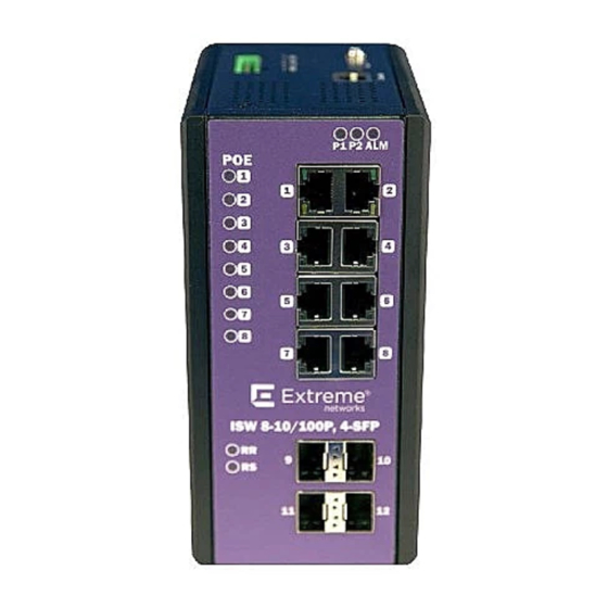
Industrial Series Switch Overview Faceplate and Panels Figure 1: 4-Port PoE Series Faceplate ISW Series Managed Industrial Ethernet Switch Quick Installation Guide... - Page 10 Industrial Series Switch Overview Figure 2: 8-Port PoE Series Faceplate Front Panel System Status LED P1, P2 and Alarm Gigabit Ethernet Copper Ports RJ45 Gigabit Ethernet SFP ports SFP Slots POE LED POE port status RR/RS LED Device info/status ISW Series Managed Industrial Ethernet Switch Quick Installation Guide...
-
Page 11: Alarm Relay And Ground Connection
Industrial Series Switch Overview Figure 3: Top Panel Top Panel Power Input (Dual) 6P Terminal Block Console (RS232) RJ45 Reset Push Button Alarm Relay and Ground Connection The alarm relay output contacts are in the middle of the DC terminal block connector as shown in Figure The alarm relay out is “Normal Open,”... -
Page 12: Led Status Indicators
Industrial Series Switch Overview Figure 4: Alarm Relay and Ground Connector LED Status Indicators Table 3: LED Status Indicators State Description On Green P1 power line has power P1 power line disconnect or does not have supply power On Green P2 power line has power P2 power line disconnect or does not have supply power... - Page 13 Industrial Series Switch Overview Table 3: LED Status Indicators (continued) State Description RR (Redundant Role) Redundant Master (Ring Master, Ring Coupling Backup, Dual Homing, Chain Head, Balancing Chain Central Block ) is enabled in the system. No Redundant Master is enabled in the system.
- Page 14 Industrial Series Switch Overview ISW Series Managed Industrial Ethernet Switch Quick Installation Guide...
-
Page 15: Chapter 2: Installation
Installation Mounting the ISW (DIN-Rail) Mounting the ISW (Wall) Connecting the Ethernet Interface (RJ45 Ethernet) Connecting the Ethernet Interface (Fiber) Connecting the Power Terminal Block Console Connection Mounting the ISW (DIN-Rail) Mounting steps: Screw the DIN-Rail bracket on with the bracket and screws in the accessory kit. 2 Hook the unit over the DIN rail. -
Page 16: Mounting The Isw (Wall)
Installation Figure 5: DIN-Rail Mounting Mounting the ISW (Wall) Attach the wall-mounting plates with the screws provided in the accessory kit. ISW Series Managed Industrial Ethernet Switch Quick Installation Guide... -
Page 17: Connecting The Ethernet Interface (Rj45 Ethernet)
Installation Connecting the Ethernet Interface (RJ45 Ethernet) ISW provides two types of electrical (RJ45) and optical (mini-GBIC) interfaces. • To connect to a PC, use a straight-through or a cross-over Ethernet cable. • To connect the ISW copper port to an Ethernet device, use UTP (Unshielded Twisted Pair) or STP (Shielded Twisted Pair) Ethernet cables. -
Page 18: Connecting The Ethernet Interface (Fiber)
Installation Figure 6: RJ45 Connector Pins Table 4: RJ45 Connector Pin Assignment Assignment PoE Assignment 1, 2 T/Rx+, T/Rx- Positive VPort 3, 6 T/Rx+, T/Rx- Negative VPort 4, 5 T/Rx+, T/Rx- 7, 8 T/Rx+, T/Rx- Connecting the Ethernet Interface (Fiber) For both 100/1000 Mbps fiber speed connections, the SFP slots are available. - Page 19 Installation Figure 8: Connect the optical fiber to the SFP socket Danger Never attempt to view optical connectors that might be emitting laser energy. Do not power up the laser product without connecting the laser to the optical fiber and putting the cover in position, as laser outputs will emit infrared laser light at this point.
-
Page 20: Connecting The Power Terminal Block
Installation Connecting the Power Terminal Block The DC power interface is a 6-pin terminal block with polarity signs on the top panel. The ISW can be powered from two power supply (input range 12V – 58V). The DC power connector is a 6-pin terminal block;... - Page 21 Installation Figure 10: ISW Console Port To connect the host PC to the switch, use the supplied RJ45 (male) connector-to-RS232 DB9 (female) connector. Connect the RJ45 connector to the switch's Console port shown in Figure 10, and then connect the DB9 connector to the PC COM port. Important Using a different cable than the one provided with the switch may cause bootup issues.
- Page 22 Installation Figure 11: Console Cable Pin Assignment ISW Series Managed Industrial Ethernet Switch Quick Installation Guide...
-
Page 23: Chapter 3: Configuration
Configuration Connecting & Logging in to the Switch Connecting & Logging in to the Switch Connect to ISW Ethernet port (RJ45 Ethernet port) using factory default IP: 192.0.2.1. 2 Log in with default account and password (admin / [none]) 3 Optional: Change the IP with commands listed below: enable configure terminal interface vlan 1... - Page 24 Configuration Chrome Google Chrome with the following default settings is recommended: Web page font Times New Roman Encoding Unicode (UTF-8) Text size Medium ISW Series Managed Industrial Ethernet Switch Quick Installation Guide...
-
Page 25: Appendix A: Regulatory And Compliance Information
Regulatory and Compliance Information Federal Communications Commission (FCC) Notice This device complies with Part 15 of the FCC rules. Operation is subject to the following two conditions: (1) this device may not cause harmful interference, and (2) this device must accept any interference received, including interference that may cause undesired operation. - Page 26 Regulatory and Compliance Information FCC 47 CFR Part 15 Subpart B Class A (US), ICES-003 (Canada) EN 55022 (ITE Emissions), EN 55024 (ITE Immunity) 2014/30/EU (EMC Directive), EN 50121‐1: 2017, EN 50121-4: 2016, EN 55011(ISM) EN 61000-6-2 (Ind. Immunity), EN61000-6-4 Ind. Emissions) EN 61000-3-2: 2014, EN 61000-3-3: 2013 RCM (Australia), MSIP KCC (Korea), BSMI (Taiwan) Korea EMC Statement (KCC)
-
Page 27: Glossary
Glossary ad hoc mode An 802.11 networking framework in which devices or stations communicate directly with each other, without the use of an AP. Address Resolution Protocol is part of the TCP/IP suite used to dynamically associate a device's physical address (MAC address) with its logical address (IP address). - Page 28 WEP keys. Unlike EAP-TLS, EAP-TTLS requires only server-side certificates. (See also PEAP (Protected Extensible Authentication Protocol).) ESRP Extreme Standby Router Protocol is an Extreme Networks-proprietary protocol that provides redundant Layer 2 and routing services to users. Extreme Access Control EAC, formerly NAC ™...
- Page 29 Glossary This can be used to better understand customer behavior on the network, identify the level of user engagement, and assure business application delivery to optimize the user experience. The software also provides visibility into network and application performance allowing IT to pinpoint and resolve performance issues in the infrastructure whether they are caused by the network, application, or server.
- Page 30 Glossary over a wide band of frequencies. This technique reduces interference. If synchronized properly, a single logical channel is maintained. (Compare with DSSS (Direct-Sequence Spread Spectrum).) IBSS An IBSS is the 802.11 term for an ad hoc network. See ad hoc mode. Message Integrity Check (or Code), also called ‘Michael’, is part of WPA and TKIP.
- Page 31 Glossary device generates a messages, a relay receives and forwards the messages, and a collector (a syslog server) receives the messages without relaying them. syslog uses the UDP as its underlying transport layer mechanism. The UDP port that has been assigned to syslog is 514.