
Related Manuals for Extreme Networks VSP 4900 Series


Summary of Contents for Extreme Networks VSP 4900 Series
-
Page 1: Hardware Installation Guide
VSP 4900 Series Switches: Hardware Installation Guide 9036268-00 Rev. AA Published October 2019... -
Page 2: Legal Notice
Copyright © 2019 Extreme Networks, Inc. All rights reserved. Legal Notice Extreme Networks, Inc. reserves the right to make changes in specifications and other information contained in this document and its website without prior notice. The reader should in all cases consult representatives of Extreme Networks to determine whether any such changes have been made. -
Page 3: Table Of Contents
Chapter 10: Removing and Replacing Components............52 Replacing an 1100 W AC Power Supply........................52 Replacing Fan Modules..............................54 Chapter 11: Replacing a Versatile Interface Module in a VSP 4900 Series Switch..56 Chapter 12: Monitoring the Switch..................57 VSP 4900 Switch LEDs..............................57 Appendix A: Technical Specifications.................. - Page 4 Table of Contents ExtremeSwitching VSP 4900 Series Switches Technical Specifications..........60 1100 W Power Supplies Technical Specifications....................65 Power Cord Requirements for AC-Powered Switches and AC Power Supplies......... 66 Appendix B: Safety and Regulatory Information..............67 Considerations Before Installing..........................67 General Safety Precautions............................68 Maintenance Safety................................68...
-
Page 5: Preface
See the and the for information about configuring ExtremeSwitching switches. Note If the information in an installation note or release note shipped with your Extreme Networks equipment differs from the information in this guide, follow the installation or release note. -
Page 6: Providing Feedback To Us
Providing Feedback to Us Quality is our first concern at Extreme Networks, and we have made every effort to ensure the accuracy and completeness of this document. We are always striving to improve our documentation and help... -
Page 7: Documentation And Training
Preface The Hub A forum for Extreme Networks customers to connect with one another, answer questions, and share ideas and feedback. This community is monitored by Extreme Networks employees, but is not intended to replace specific guidance from GTAC. Call GTAC For immediate support: 1-800-998-2408 (toll-free in U.S. - Page 8 Preface Training Extreme Networks offers product training courses, both online and in person, as well as specialized certifications. For more information, visit www.extremenetworks.com/education/. VSP 4900 Series Switches: Hardware Installation Guide...
-
Page 9: Chapter 1: Overview Of The Vsp 4900 Series Switch
Management A serial console port on the rear panel of the VSP 4900 series switch allows you to connect a terminal and perform local management. An Ethernet management port can be used to connect the system to a... -
Page 10: Vsp 4900-48P Features
Overview of the VSP 4900 Series Switch out of bound management network for administration. Alternatively, you can use an Ethernet cable to connect this port directly to a laptop to view and locally manage the switch configuration. The Ethernet management port supports 10/100/1000 Mbps speeds. -
Page 11: Vsp License Options
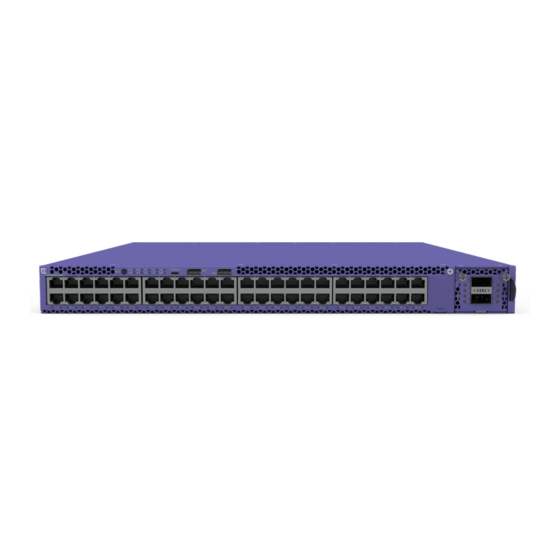
Overview of the VSP 4900 Series Switch Figure 1: VSP 4900 Series Switch: Front Panel 1 = Mode Button and System LEDs 3 = USB A ports 5 = VIM slot, shown with VIM installed 2 = USB micro B management port... -
Page 12: Chapter 2: Power Supplies For Use With Your Switch
Switch 1100 W AC Power Supplies Each VSP 4900 Series switch runs with two replaceable internal power supply units that provide all of the power needed for the switch to operate. You can remove one power supply without interrupting the switch's operation. -
Page 13: Chapter 3: Expansion Modules
You can install a VIM5 versatile interface module in a dedicated slot in the front panel of the ExtremeSwitching VSP 4900 Series switch to provide a dedicated high speed port. The front panel of every VSP 4900 switch provides one slot to install the following: •... - Page 14 Disabled Enabled for DAC negotiation Disabled for Fiber Auto-FEC enabled for DAC and Fiber MACsec 256bit 256bit * The user must set vim-speed to 10G or 25G for VIM5-2Y. The default is 25G. VSP 4900 Series Switches: Hardware Installation Guide...
- Page 15 The VIM5-4XE versatile interface module provides four 10-GbE (SFP+) ports, LRM/MACsec capable. For information about the supported optical modules, refer to the most recent version of the Extreme Hardware/Software Compatibility and Recommendation Matrices. VSP 4900 Series Switches: Hardware Installation Guide...
- Page 16 The user must set vim-speed to 10G or 25G for VIM5-2Y. The default is 25G. For details about the vim-speed command, see the Command Line Interface Commands Reference for VOSS. For information about the supported optical modules, refer to the most recent version of the Extreme Hardware/Software Compatibility and Recommendation Matrices. VSP 4900 Series Switches: Hardware Installation Guide...
- Page 17 Command Line Interface Commands Reference for VOSS. For information about the supported optical modules, refer to the most recent version of the Extreme Hardware/Software Compatibility and Recommendation Matrices. VSP 4900 Series Switches: Hardware Installation Guide...
- Page 18 For the VIM5-2Q versatile interface module, only the first 40-GbE (QSFP) port is supported. For information about the supported optical modules, refer to the most recent version of the Extreme Hardware/Software Compatibility and Recommendation Matrices. VSP 4900 Series Switches: Hardware Installation Guide...
- Page 19 Figure 8: VIM5-2Q Versatile Interface Module Table 11: Port Numbers for Ports on the VIM5-2Q Module ExtremeSwitching VSP4900 Port Number for 48-port Models 49 in unchannelized mode 49/1, 49/2, 49/3, and 49/4 in channelized mode VSP 4900 Series Switches: Hardware Installation Guide...
-
Page 20: Chapter 4: Preparing To Install
Meeting Power Requirements Following Applicable Industry Standards Before you install your Extreme Networks equipment, careful planning can help ensure that it is used effectively and help prepare you for future growth. Only qualified service personnel should install, maintain, or remove a switch, chassis, or its components. -
Page 21: Operating Environment Requirements
“UL Approved” or “UL Listed.” National Electrical Manufacturing Association (NEMA) (USA NEMA www.nema.org only) 1300 N. 17th Street Organization of electrical product manufacturers. Members Rosslyn, VA 22209 develop consensus standards for cables, wiring, and electrical components. VSP 4900 Series Switches: Hardware Installation Guide... - Page 22 Controlling the Temperature Extreme Networks equipment generates a significant amount of heat. It is essential that you provide a temperature-controlled environment for both performance and safety. Install the equipment only in a temperature- and humidity-controlled indoor area that is free of airborne materials that can conduct electricity.
-
Page 23: Rack Specifications And Recommendations
Alternately, you can restart the system immediately by removing and then restoring all line power to the system. Safeguards are built into all Extreme Networks switches and power supply units to minimize the risk of fire. Controlling the Humidity Level To maximize equipment life, keep operating humidity between 50% and 70% relative humidity (non- condensing) during typical operation. -
Page 24: Mechanical Recommendations For The Rack
This will ensure good grounding between the chassis, rack, and earth ground. Note Because building codes vary worldwide, Extreme Networks strongly recommends that you consult an electrical contractor to ensure proper equipment grounding for your specific installation. -
Page 25: Evaluating And Meeting Cable Requirements
Evaluating and Meeting Cable Requirements Use professional consultants for site planning and cabling. Extreme Networks recommends using the Building Industry Consulting Service International (BICSI) Registered Communications Distribution Designer (RCDD), which is globally recognized as a standard in site planning and cabling. -
Page 26: Installing Cable
Assign a unique block of sequential numbers to the group of cables that run between each pair of wiring closets. • Assign a unique identification number to each equipment rack. • Identify all wiring closets by labeling the front panel of your Extreme Networks equipment and other hardware. • Keep accurate and current cable identification records. •... - Page 27 Every cable has a minimum bend radius, example, and fibers will be damaged if the cables are bent too sharply. It is also important not to stretch the cable during installation. Extreme Networks recommends VSP 4900 Series Switches: Hardware Installation Guide...
- Page 28 Table 13: Cable Distances and Types Standard Media Type MHz•km Maximum Distance Rating (Meters) 1000BASE-SX 50/125 µm multimode fiber (850nm optical window) 50/125 µm multimode fiber 62.5/125 µm multimode fiber 62.5/125 µm multimode fiber VSP 4900 Series Switches: Hardware Installation Guide...
- Page 29 10BASE-T Category 3 and higher UTP cable – Proprietary to Extreme Networks. Connections between two Extreme Networks 1000BASE-LX interfaces that use 10/125 µm single-mode fiber can use a maximum distance of 10,000 meters. VSP 4900 Series Switches: Hardware Installation Guide...
- Page 30 Preparing to Install Table 14 Table 15 on page 30 list direct-attach cables available from Extreme Networks. Table 14: Extreme Networks 100Gb Direct-Attach Cables Cable Type Part Number Length QSFP28-QSFP28 Direct attach passive copper cable 10411 or AA1405029-E6 1 meter...
-
Page 31: Meeting Power Requirements
In areas or applications where these situations cannot be avoided, use fiber optic cabling or shielded twisted pair cabling. Meeting Power Requirements Observe the following requirements and precautions for powering your hardware. Power Supply Requirements Follow these recommendations when you plan power supply connections for your equipment: VSP 4900 Series Switches: Hardware Installation Guide... - Page 32 Extreme Networks equipment. The web page provides specifications for power cords in each country so that you can purchase cords locally. UPS (Uninterruptible Power Supply) Requirements...
-
Page 33: Following Applicable Industry Standards
UPS transfer time. UPS transition times vary between UPS models and implementations, but shorter transition times are preferred. For Extreme Networks stacking products, we recommend a UPS transition time of 20 milliseconds or less to ensure optimum performance and minimize service interruptions. - Page 34 Preparing to Install • ANSI/TIA/EIA-606—cabling system administration • ANSI/TIA/EIA-607—commercial building grounding and bonding requirements You can access these standards at: www.ansi.org or www.tiaonline.org. VSP 4900 Series Switches: Hardware Installation Guide...
-
Page 35: Chapter 5: Installing Your Switch
Installing Optional Components Installing Internal AC Power Supplies Powering up the Switch Connecting Network Interface Cables Before you attempt to install or remove an Extreme Networks switch, read the precautions in Safety Considerations for Installing Switches on page 36. Extreme Networks switches fit into standard 19-inch equipment racks. -
Page 36: Safety Considerations For Installing Switches
20, and ensure that you have the appropriate people and tools on hand. Installing Extreme Networks switches is easiest when there are two people to maneuver the switch and attach mounting hardware. Provide enough space in front of and behind the switch so that you can service it easily. Allow a minimum of 122 cm (48 in) in front of the rack and 76 cm (30 in) behind the rack. -
Page 37: Attaching The Switch To A Rack Or Cabinet
• Figure 14 shows a front-mount configuration using a short mounting bracket. Note For some switch models, only short mounting brackets are provided. Figure 13: Mid-Mount: Attaching a Long Mounting Bracket VSP 4900 Series Switches: Hardware Installation Guide... - Page 38 Figure 15: Sliding the Switch into the Rack 5 Secure the mounting bracket flanges to the rack, using screws that are appropriate for the rack. (Rack-mounting screws are not provided.) VSP 4900 Series Switches: Hardware Installation Guide...
- Page 39 Installing Optional Components on page 40. Then, if your switch does not have an installed power supply, install one or two power supplies using the instructions in Installing Internal AC Power Supplies on page 40. VSP 4900 Series Switches: Hardware Installation Guide...
-
Page 40: Installing Optional Components
An AC power cord is not included with an AC power supply. You can purchase AC power cords for use in the US and Canada from Extreme Networks or from your local supplier. The cord must meet the requirements listed under... - Page 41 An AC power cord is not included with the AC power supply. You can purchase AC power cords for use in the US and Canada from Extreme Networks or from your local supplier. The cord must meet the requirements listed in Power Cord Requirements for AC-Powered Switches and AC Power Supplies page 66.
-
Page 42: Powering Up The Switch
An AC power cord is not included with the AC power supply. You can purchase AC power cords for use in the US and Canada from Extreme Networks or from your local supplier. The cord must meet the requirements listed in Power Cord Requirements for AC-Powered Switches and AC Power Supplies page 66. - Page 43 Installing Your Switch 6 Dress and secure the cable bundle to provide appropriate strain relief and protection against bends and kinks. VSP 4900 Series Switches: Hardware Installation Guide...
-
Page 44: Chapter 6: Activating And Verifying The Switch
Using a terminal emulator such as PuTTY or TeraTerm, connect to the switch using the serial port connection. Be sure that your serial connection is set properly: • Baud rate: 115200 • Data bits: 8 • Stop bit: 1 VSP 4900 Series Switches: Hardware Installation Guide... - Page 45 4 Follow the steps for provisioning and verifying the switch in Quick Start Configuration for VOSS. The switch is ready for use. To configure security, see Configuring Security. To configure other switch features, see Documentation Reference. VSP 4900 Series Switches: Hardware Installation Guide...
-
Page 46: Chapter 7: Installing Expansion Modules
Installing Expansion Modules Installing a Versatile Interface Module in a VSP 4900 Series Switch This chapter describes how to install expansion modules: • Versatile interface modules (VIM5s) Note Read the information in this chapter thoroughly before trying install or remove an expansion module. - Page 47 Insert and tighten the retaining screws you removed in step on page 47, using the screws provided. Figure 19: Tighten Screws on the Inserted VIM5 Module 1 = VIM5 module retaining screw locations VSP 4900 Series Switches: Hardware Installation Guide...
-
Page 48: Chapter 8: Removing Switches From Service
2 Remove the switch from the rack, following the steps in Removing the Switch from the Rack page 49. Note Read the information in this chapter thoroughly before you attempt to remove a switch. VSP 4900 Series Switches: Hardware Installation Guide... -
Page 49: Chapter 9: Removing The Switch From The Rack
Carefully slide the switch out of the slider assembly and place it on a flat surface. You can leave the slider assemblies in place. If you want to remove them, continue with step 3.d. VSP 4900 Series Switches: Hardware Installation Guide... - Page 50 Removing the Switch from the Rack d On one of the slider assemblies, push the rear clamp until it separates from the rear rack post. Figure Figure 21: Removing the Slider Assembly: Rear Rack Post VSP 4900 Series Switches: Hardware Installation Guide...
- Page 51 If you plan to use the switch again later, we recommend storing it with the mounting brackets attached. VSP 4900 Series Switches: Hardware Installation Guide...
-
Page 52: Chapter 10: Removing And Replacing Components
Disconnect the AC power cord from the wall outlet and from the power supply. 2 Note the orientation of the installed power supply, and the location of the latching tab at the right of the unit. VSP 4900 Series Switches: Hardware Installation Guide... - Page 53 Unoccupied bays must always be covered to maintain proper system ventilation and EMI levels. 5 Verify that the replacement power supply is oriented the same way as the unit you removed, and has the same airflow direction. VSP 4900 Series Switches: Hardware Installation Guide...
-
Page 54: Replacing Fan Modules
All installed fan modules must blow air in the same direction and must match the airflow direction of the installed power supplies. • If the switch's fan tray has a red tab, the airflow is front-to-back. Use a fan module labeled Air Out. VSP 4900 Series Switches: Hardware Installation Guide... - Page 55 Fans with back-to-front airflow have blue tabs and are labeled Air In. 4 Carefully slide the replacement fan module into the switch. Push until the fan module snaps into place. The fan will automatically start to operate. VSP 4900 Series Switches: Hardware Installation Guide...
-
Page 56: Chapter 11: Replacing A Versatile Interface Module In A Vsp 4900 Series Switch
#1 Phillips screwdriver (for clock module) or flat-bladed screwdriver (for all other VIM modules) Caution Extreme Networks VIMs are not hot-swappable. Disconnect power to the switch before removing an installed VIM or installing a new VIM. The replacement procedure is the same all VSP 4900 VIM5s. -
Page 57: Chapter 12: Monitoring The Switch
Mode button is used to cylce through two display modes for the port LEDs. SYS and SPD display modes will expire after 30 seconds, at which time the port LEDs will revert to the default SYS mode. VSP 4900 Series Switches: Hardware Installation Guide... - Page 58 Color and blink pattern indicate speeds, as referenced by the following table: Table 18: Port LEDs in SPD Mode Color/State Speed Steady green 10Mbps Blinking green 100Mbps Steady amber 1000Mbps Steady green 10Gbps VSP 4900 Series Switches: Hardware Installation Guide...
- Page 59 Monitoring the Switch Table 18: Port LEDs in SPD Mode (continued) Color/State Speed Blinking amber 25Gbps Blinking green 40Gbps VSP 4900 Series Switches: Hardware Installation Guide...
-
Page 60: Appendix A: Technical Specifications
Power Cord Requirements for AC-Powered Switches and AC Power Supplies This section lists technical specifications for the hardware products described in this document. ExtremeSwitching VSP 4900 Series Switches Technical Specifications The ExtremeSwitching VSP 4900 series includes the following switch: • VSP4900-48P switch Table 19: VSP 4900 Unpackaged Dimensions VSP4900-48P switch Height: 1.72 inches (4.36 cm) - Page 61 Height: 1.57 inches (3.99 cm) Width: 1.92 inches (4.88 cm) Length: 6.16 inches (15.64 cm) VIM5-4YE 18.77 lb (8.51 kg) Height: 1.57 inches (3.99 cm) Width: 1.92 inches (4.88 cm) Length: 6.16 inches (15.64 cm) VSP 4900 Series Switches: Hardware Installation Guide...
-
Page 62: Power Options
50/60 Hz, 10.5A/5.0 A max per PS Bystander Sound pressure is presented for comparison to other products measured using Bystander Sound Pressure. Declared Sound Power is presented in accordance with ISO 7779:2010(E), ISO 9296:2010 per ETSI/EN 300 753:2012-01. VSP 4900 Series Switches: Hardware Installation Guide... - Page 63 EN 60825-1:2007 (Lasers Safety) IEC/EN 62368-1 2nd, IEC/EN 60950-1 A2 EN 62368-1:2014/A11:2017 International Safety of ITE CB Report & Certificate per IEC 60950-1:2005 2nd Ed., + National Differences AS/NZX 60950-1 (Australia /New Zealand) VSP 4900 Series Switches: Hardware Installation Guide...
- Page 64 Table 34: IEEE 802.3 Media Access Standards IEEE 802.3ab 1000BASE-T IEEE 802.3z 1000BASE-X IEEE 802.3ae 10GBASE-X IEEE 802.3ba 40GBASE-X IEEE 802.3bz 2.5GBASE-T and 5GBASE-T (for X460-G2-16mp-32p-10GE4) IEEE 802.3at PoE Plus IEEE 802.3az (EEE) VSP 4900 Series Switches: Hardware Installation Guide...
-
Page 65: 1100 W Power Supplies Technical Specifications
14 drops minimum on sides and corners at 42 inches (<15 kg box) 1100 W Power Supplies Technical Specifications AC Power Supplies The following 1100 W AC power supply is available for use in VSP 4900 series switches. • 1100 W AC power supply: front-to-back airflow (part no. 10941) -
Page 66: Power Cord Requirements For Ac-Powered Switches And Ac Power Supplies
The power cords for switches that use either the 1100 W or 715 W power supplies are keyed with a “notch” to ensure the proper orientation when plugged in. These cords are of 3x14 AWG. For details about obtaining AC power cords for use in your country, refer to http:// www.extremenetworks.com/product/powercords/. VSP 4900 Series Switches: Hardware Installation Guide... -
Page 67: Appendix B: Safety And Regulatory Information
Only trained and qualified service personnel (as defined in IEC 60950-1 and AS/NZS 3260) should install, replace, or perform service to Extreme Networks switches and their components. Qualified personnel have read all related installation manuals, have the technical training and experience necessary to be aware of the hazards to which they are exposed in performing a task, and are aware of measures to minimize the danger to themselves or other persons. -
Page 68: General Safety Precautions
Make sure that your power supplies meet the site DC power or AC power requirements of all the network equipment. • Racks for Extreme Networks equipment must be permanently attached to the floor. Failure to stabilize the rack can cause the rack to tip over when the equipment is removed for servicing. •... -
Page 69: Fiber Optic Ports And Optical Safety
Install all cables in a manner that avoids strain. Use tie wraps or other strain relief devices. Fiber Optic Ports and Optical Safety The following safety warnings apply to all optical devices used in Extreme Networks equipment that are removable or directly installed in an I/O module or chassis system. -
Page 70: Cable Routing For Lan Systems
47 CFR Part 15, Class A when installed into Extreme products Cable Routing for LAN Systems Extreme Networks equipment meets the requirements for LAN system equipment. LAN systems are designed for intra-building installations; that is, cable runs between devices must be in the same building as the connected units, except under the conditions listed in the next paragraph. -
Page 71: Installing Power Supply Units And Connecting Power
When you install DC power supplies or connect DC power: • Extreme Networks DC power supplies do not have switches for turning the unit on and off. Make sure that the DC circuit is de-energized before connecting or disconnecting the DC power cord at the DC input power socket. -
Page 72: Battery Notice
Il y a risque d’explosion si la pile est remplacée par un type de pile incorrect. Éliminez les piles usées en conformité aux règlements locaux d'élimination des piles. Battery Warning - Taiwan VSP 4900 Series Switches: Hardware Installation Guide... -
Page 73: Emc Warnings
This is a Class A product based on the standard of the VCCI Council. If this equipment is used in a domestic environment, radio interference may occur, in which case the user may be required to take corrective actions. VSP 4900 Series Switches: Hardware Installation Guide... -
Page 74: Korea Emc Statement
Safety and Regulatory Information Korea EMC Statement VSP 4900 Series Switches: Hardware Installation Guide... -
Page 75: Index
5 26 temperature 22 fiber optic 27, 42 wiring closet 22 for switch ports 42 equipment installing 26, 27 installing 35 labeling 25 tools needed to install 36 network interface 42 equipment rack optical 40 grounding 24 plenum-rated 26 mechanical recommendations 24 RJ45 30 mounting holes 24 slack 26 securing 25 VSP 4900 Series Switches: Hardware Installation Guide... - Page 76 VSP 4900 switch 62, 63 VIM5 module 46 power supply unit (PSU) 1100 W AC 12, 40 2000 W AC 40 715 W AC 40 jackets for VSP 4900 switches 62 RJ45 connector 30 installing 40 VSP 4900 Series Switches: Hardware Installation Guide...
- Page 77 VOSS switches initial login 44 attaching to cabinet 37 license options 11 attaching to rack 37 VSP 4900 series switches connecting power 42 acoustic noise 61 initial login 44 fan speed 62 installing 35 features 9, 10 installing optional components 40 VSP 4900 Series Switches: Hardware Installation Guide...
- Page 78 (PSU) 62 specifications 60, 62, 63 VSP4900-48P switch 9, 10 VSP 4900 Series switches features 10 LEDs 57, 58 VSP Series switches license options 11 wiring closet electrostatic discharge (ESD) 23 floor coverings 22 grounding 22 humidity 23 rack, securing 25 temperature 22 wiring terminals 24 VSP 4900 Series Switches: Hardware Installation Guide...