Table of Contents
Advertisement
Advertisement
Table of Contents

Related Manuals for Siemens ADVIA 2400


Summary of Contents for Siemens ADVIA 2400
- Page 1 ADVIA ® 2400 Chemistry System Operator's Guide 073D0403-01 Rev. A, 2009-06...
- Page 2 If the system is used in a manner not specified by Siemens, the protection provided by the equipment may be impaired. Observe all warning and hazard statements. The ADVIA Chemistry system is manufactured in Japan for Siemens.
-
Page 3: Table Of Contents
Table of Contents 1 System Overview ........................... 13 Operating principle ........................... 13 Hardware Overview........................... 14 Display and power panel............................15 Analyzer back view ..............................15 Analyzer top view..............................16 Vertical Pumps.................................17 Horizontal Pumps ..............................17 Workstation (front view) ............................18 PC (front view) .................................18 PC (back view).................................19 Sampling and analysis .............................19 Sampling mechanisms.............................19 Sampling operation .............................19... - Page 4 View Calibration Curve window...........................45 Calibration/RBL History ............................45 Sample Select window*............................46 Calibration Setup window* ..........................46 Maintenance windows..............................46 System Startup/Shutdown Setting window......................46 User Maintenance window ..........................47 System Monitor window ............................47 System Maintenance Monitor window .........................47 Lamp Energy Monitor window ..........................47 ADVIA 2400 Operator’s Guide...
- Page 5 ISE Operation window............................47 ISE Monitor window.............................48 Manual Operation window...........................48 On-Line Monitor window............................48 Error Report window* ............................49 Reagent windows ..............................49 Reagent Inventory window ..........................49 CTT Monitor window ............................49 Reagent Container Settings window ........................49 Active Test List window*............................50 Reagent Information window* ..........................50 Reagent Barcode Maintenance window*......................51 QC windows................................51 ADVIA QC window ..............................51...
- Page 6 Viewing the sample log entries..........................84 Searching the sample log............................84 Deleting a specific sample log entry ........................85 Deleting all sample log entries ..........................85 Printing a list of the sample log entries........................85 Exporting the sample log entries .........................86 ADVIA 2400 Operator’s Guide...
- Page 7 Reviewing the calibration results ..........................86 Reviewing the sample results ..........................86 Reporting results..............................86 Real-time reporting..............................86 Batch transmission to a host computer .......................87 Printing sample data ..............................87 Batch Printing..............................88 Shutting down the ADVIA Chemistry system ..................88 Examples of shutdown settings ..........................89 System available during the night ........................89 Automatic startup from the Sleep state .......................89 Automatic startup with analyzer power kept ON....................89...
- Page 8 Every 2 months maintenance ........................ 131 Cleaning the dilution tray cuvettes .........................131 Cleaning and replenishing the cuvette conditioner bottle..................132 Every 3 months maintenance ........................ 133 Replacing the lamp ..............................133 Washing the ISE electrodes lines ..........................135 Every 4 months maintenance ........................ 137 ADVIA 2400 Operator’s Guide...
- Page 9 Cleaning the ancillary reagent bottle filters ......................137 Cleaning the pure-water bottle filter ........................137 Replacing the reaction and dilution cuvettes......................140 As required maintenance ........................143 Backing up system files ............................143 Restoring system files............................144 Replacing the SPP, RPP1, and RPP2 probes .......................144 Remove the probe.............................145 Install a new probe..............................146 Replacing DPP probes equipped with crash detection ..................147...
- Page 10 Replacement of parts.............................184 Warranty and service exclusions ...........................184 Design changes and retrofitting of instruments ....................186 OSHA requirements ............................186 Software License ..............................186 ADVIA Contact information ............................187 Siemens Worldwide............................187 Appendix C –Customer replaceable parts.................... 188 Appendix D – Specifications........................190 ADVIA 2400 Operator’s Guide...
- Page 11 Specifications – all ..............................190 Appendix E – Symbols ........................... 194 Explanations of symbols associated with the ADVIA 2400 system ..........194 Warning and caution symbols..........................194 System operation symbols.............................195 System rating label symbols ..........................196 Hardware component symbols ..........................197 Ancillary reagent symbols ............................197 Connector symbols ..............................198...
- Page 12 ADVIA 2400 Operator’s Guide...
-
Page 13: System Overview
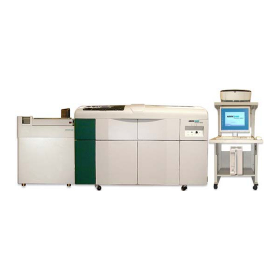
1800 photometric tests per hour and 600 electrolyte tests per hour. The ADVIA 2400 Chemistry System is for in vitro diagnostic use. Operating principle This sequence summarizes a photometric analysis on the Chemistry System: 1. -
Page 14: Hardware Overview
Isotonic saline diluent bottle Reaction bath oil pump Horizontal pumps Cuvette detergent bottle Reaction bath oil filter Vertical pumps Cell conditioner bottle Power panel ISE buffer bottle Reaction bath oil heater Display panel Figure 1-2. Analyzer front view ADVIA 2400 Operator’s Guide... -
Page 15: Display And Power Panel
Display and power panel READY lamp lights when the instrument is ready. START lamp lights when analysis is being performed. ALARM lamp lights when a problem occurs. SYSTEM RESET button resets the computer controlling the instrument (not normally used). EMERGENCY STOP button is pressed to stop the instrument in an emergency. -
Page 16: Analyzer Top View
Reaction tray (RRV) Dilution tray (DTT) Reagent tray 2 (RTT2) Dilution washer (DWUD) Reagent tray 1 (RTT1) Sample probe (SPP) Reagent probe 1 (RPP1) Reaction tray washer (WUD) Reagent probe 2 (RPP2) Figure 1-5. Analyzer top view ADVIA 2400 Operator’s Guide... -
Page 17: Vertical Pumps
Vertical Pumps Dilution wash pump (DCP) Reagent dispensing pump 1 (RP1) Dilution aspiration pump (DIP) Reagent wash pump 1 (RWP1) Dilution discharge pump (DOP) Reagent dispensing pump 2 (RP2) Sampling wash pump (SCP) Reagent wash pump 2 (RWP2) Sampling pump (SP) Figure 1-6. -
Page 18: Workstation (Front View)
PC hard disk drive access lamp. Lights when reading or writing to the PC hard disk. PC power lamp. Lights when the power for the personal computer is ON. USB ports Figure 1-9. PC front view ADVIA 2400 Operator’s Guide... -
Page 19: Pc (Back View)
PC (back view) PC power connector Mouse connection Keyboard connector Communication port 1 (LIS-TDC) Printer connector LCD monitor connection Analyzer Ethernet connection Communication port 2 (URH) Sleep ITF board potentiometer Figure 1-10. PC back view Sampling and analysis Sampling mechanisms The sample probe (SPP) aspirates sample from the dilution tray (DTT) and dispenses it into reaction tray (RRV) cuvettes for analysis, according to specified conditions. -
Page 20: Sample Probe
After the sample is aspirated, the SPP moves to the wash port, where its outside is washed. Sample probe valve (SPEV2) is open during this process, allowing water to flow over the outside of the SPP. ADVIA 2400 Operator’s Guide... -
Page 21: Clot Detection
After the sample is dispensed, the SPP moves back to the wash port, where its inside is washed. Sample probe valve (SPEV1) opens, allowing the SCP to send degassed water through the SPP’s inside. After the wash, the water drains down the wash port. Clot detection The clot detection system utilizes a pressure transducer to monitor the pressure in the sample dilution probe line (DPP) for a complete obstruction during the sample aspiration... -
Page 22: Reaction Tray Mixers
Mixing is performed using a spinning, reciprocating, and vibrating paddle. Strong and weak stirring options are available. Both mixers are located behind the reaction tray. MIXR1 mixes sample with reagent 1 (R1). MIXR2 mixes sample with reagent 2 (R2). Reaction tray wash mechanisms Reaction washer (WUD) ADVIA 2400 Operator’s Guide... - Page 23 Figure 1-15 Reaction tray washer The reaction washer (WUD) washes reaction tray (RRV) cuvettes after sample analysis is complete. This allows the reuse of cuvettes without the risk of contaminating the next sample. The WUD has seven nozzles, each performing a stage of the wash. Each nozzle works on a different cuvette, so the WUD washes seven cuvettes simultaneously (the cuvettes are being washed in different stages at the same time).
-
Page 24: Reaction Tray Washer Operation
The fourth (4) and fifth (5) nozzles are NOTE: separated by a width of six cuvettes. 5 Fifth nozzle Aspirates cell conditioner. Dispenses wash water. Absorbs overflow liquid (abnormal conditions). 6 Sixth nozzle Aspirates wash water. 7 Seventh nozzle Figure 1-16. Nozzle separation ADVIA 2400 Operator’s Guide... -
Page 25: Reaction Tank
Reaction tank Reaction tank Three liquid surface level sensors Figure 1-17 Reaction tank The reaction tank contains non reactive oil, which keeps the temperature of the liquid in reaction tray (RRV) cuvettes at a constant 37 °C ±0.1 °C. The temperature is controlled by a heater and a thermostat. -
Page 26: Sample Tray Operation
The text on the SMP Pause button located on the Operation Panel is gray when inactive and black when active. • For more information on using the SMP Pause button, refer to the online Operator’s Guide. ADVIA 2400 Operator’s Guide... -
Page 27: Spectrophotometer
Spectrophotometer Photometer Halogen Lamp Cooling Tank Figure 1-19. Location of the Spectrophotometer The spectrophotometer measures the amount of light absorbed at 14 specific wavelengths by liquids contained in reaction cuvettes. Every six seconds, the reaction tray (RRV) moves cuvettes containing reaction liquid (sample and reagent) in front of a halogen lamp, which sends light through the cuvettes. -
Page 28: Reagent Trays
Each tray has 50 positions. RTT1 contains the first reagent (R1); RTT2 contains the second reagent (R2). You can use any reagent container for more than one test item; a test item may require more than one reagent container. Each reagent tray has a barcode reader (RBC-1 and RBC-2). ADVIA 2400 Operator’s Guide... -
Page 29: Reagent Probes
Reagent probes Reagent probe 1 (RP1) Reagent wash pump 1 (RWP1) Reagent wash pump 2 (RWP2) Reagent probe 2 (RP2) Figure 1-21 Reagent probes Reagent pumps Reagent pump 1 (RP1) Reagent pump 2 (RP2) Reagent wash pump 1 (RWP1) Reagent wash pump 2 (RWP2) Figure 1-22 Reagent pumps The reagent pumps (RP1 and RP2) withdraw reagent from the reagent trays, and also discharge the reagent into the RRV cuvettes. -
Page 30: Reagent Tray Operation
• sample diluted with special purpose diluent • undiluted sample For more detailed information on how sampling is dispensed, refer to the online under Operator’s Guide Hardware Overview – Sample dilution ADVIA 2400 Operator’s Guide... -
Page 31: Dilution Tray Mixer
Dilution tray mixer The dilution tray (DTT) mixer (DMIX) stirs the contents of DTT cuvettes brought to the mixer position. Mixing is performed using a reciprocating rod. Dilution Mixer (DMIX) Figure 1-23. Dilution tray mixer Dilution tray mixer operation At the time of system initialization, the mixer moves to the mixer position, then goes to the down position. - Page 32 After a cuvette is washed by one nozzle, it moves to the next until washing is complete. While the DTT rotates, the DWUD is in the up position. ADVIA 2400 Operator’s Guide...
-
Page 33: Dilution Tray Wash Mechanism Operation
Dilution tray wash mechanism operation At initialization, the DWUD moves to the up position. If it is already up, it is lowered, then raised. During each 2-second cycle on the DTT, the 10 nozzles operate as follows: Nozzle Probe Description First nozzle Aspirates wash water. -
Page 34: Ise (Electrolyte Analyzer)
DPEV Cl Electrode ISE Degassing Unit Mixer Buffer Solution Waste Block Figure 1-26. ISE components To ensure data accuracy, undiluted sample is aspirated from the sample tray and electrolyte analysis is always performed before photometric sampling. ADVIA 2400 Operator’s Guide... -
Page 35: Universal Rack Handler - Functional Description (Optional)
Universal rack handler – functional description (optional) The universal rack handler is a separate sample delivery mechanism designed to allow operators to continuously load samples. The operator can load five sample containers into each rack and up to fifteen racks (75 samples) on each rack carrier to improve workflow efficiency. -
Page 36: Software Overview
This window opens after you start the system software from the Startup window. Use this window for the following tasks: • perform routine tasks on the Chemistry system • check the system status and alarm messages ADVIA 2400 Operator’s Guide... -
Page 37: Buttons
Buttons You select buttons on the Operation Panel to perform routine tasks. Start Wash Initialize Pause Stop Prime Host Pause On/Off Error log Audible Operator's Alarm Guide Figure 1-28. Operation Panel buttons Status and message boxes The boxes on the right of the Operation Panel provide information on current system conditions. -
Page 38: Menu Panel
2. Enter the new user name (access level) and the corresponding password. Or, do not type a password at the Password window to log in as a user. 3. Select You are now logged in as the new user. ADVIA 2400 Operator’s Guide... - Page 39 Changing the system password Use this procedure to change the password for the supervisor ID. 1. At the System menu, select Change password 2. At the Change Password window, enter the old password, then enter the new password. 3. Enter the new password again in the Confirm password box. If you are setting the password for the first time, leave the Old password box blank.
-
Page 40: Description Of Software Windows
Rerun Description Results • search the sample log • delete a specific sample log entry • delete all sample log entries • print a list of the sample log entries • export the sample log entries ADVIA 2400 Operator’s Guide... -
Page 41: Test Result Monitor Window
Test Result Monitor window Use this window to monitor an analysis while it is running. At the Test Result Monitor window, you can monitor the following: • processing status • The center of the window resembles the sample tray. The outer ring is the STT tray; the inner ring is the CTT tray. - Page 42 TT No. list box. If this is a barcode analysis, the TT number is 0. To view the status of prior tray samples that are still in process, select the down arrow of the TT No. list box, then select the number of the tray you want to view. ADVIA 2400 Operator’s Guide...
-
Page 43: Review/Edit Window
Review/Edit window CAUTION Tests on the Review/Edit window must be in the same order as they appear in the System Test List window to avoid incorrect positioning of results on the print report. You must not modify the order of the test items on the System Test List window after initial setup. -
Page 44: Print Report Window
For the current analysis, you can override the settings in the Temp cup/tube select window. Test Utilization Statistics window Use this window to monitor the test utilization against Patient, Calibrations, and Controls. All tests defined on the system are displayed. NOTE: ADVIA 2400 Operator’s Guide... -
Page 45: Correlation Window
Correlation window* Use this window to create and display correlation charts and the data that displays in the charts. When needed, use the correlation data to create a real time correction formula in the Analytical Parameters (Chemistry) window (or ISE Parameters of Setting window). Perform any of the following tasks at this window: •... -
Page 46: Sample Select Window
Maint. System Startup/Shutdown Setting window Perform any of the following tasks at this window: • perform a system-assisted startup (Start set) • perform a system-assisted shutdown (Shutdown set) • perform an automatic startup (Auto start set) ADVIA 2400 Operator’s Guide... -
Page 47: User Maintenance Window
User Maintenance window Perform any of the following tasks at this window: • water blank measurement • cell blank measurement • batch printing • filing of measurement data • save of text file System Monitor window Perform any of the following tasks at this window: •... -
Page 48: Ise Monitor Window
• transfer calibration data to the ISE * The selectivity check must be performed under the supervision of authorized Siemens service personnel. Please call your local technical support provider or distributor. Manual Operation window Perform any of the following tasks at this window: •... -
Page 49: Error Report Window
Error Report window* Use the Error Report window to review system status and error messages. If the column has a drop-down arrow you can sort the column. You can also search by Samp ID, Safe No, and Test Name. For each message, the following information displays: Icon Samp.ID Safe. -
Page 50: Active Test List Window
The Reagent Inventory and Reagent Container Set windows use this information. is the test method name. Assay Name is the reagent code for each Siemens barcoded reagent container or a 5 digit user R-Code defined code for non-barcoded reagents. specifies the on-system reagent stability. -
Page 51: Reagent Barcode Maintenance Window
Reagent Barcode Maintenance window* Access to this window is through a tech_manager and service logon level only. NOTE: Please contact your technical service provider or distributor in order to change the default settings on this window. Use this window to maintain barcode information for the reagents in RTT1 and RTT2. To confirm that the correct barcode is scanned, use the Reagent Barcode Confirmation window. -
Page 52: Real-Time Qc Window
QC cumulative window as a data point for the current day. IMPORTANT To avoid losing QC statistics, please observe the following: Update the QC Cumulative window before more than 20 daily control samples are run. ADVIA 2400 Operator’s Guide... -
Page 53: Qc Cumulative Window
The QC Daily Precision Control window can manage a maximum of 20 results for each control product (level). Only the most current QC data are saved when more than twenty controls are run in a day. (If an additional control sample is run, the oldest control sample is deleted to make room for the new one. -
Page 54: Sample Select Window
Settings that take effect after the next New Start • basic system composition • basic system operation Settings that take effect after startup operation from READY state • sample containers • reagent bottles • Serum indices specifications ADVIA 2400 Operator’s Guide... -
Page 55: Analytical Parameters (Chemistry) Window
Analytical Parameters (Chemistry) window* Use this window to set up chemistry methods. Siemens methods are predefined when the system is received. For predefined methods, only expected values, rerun conditions, and correction formulas should be modified. You can define new methods. The system can store up to 200 chemistry methods in this window (including predefined methods). -
Page 56: System Test List Window
Methods 1–150 are predefined methods. The analytical conditions are predefined. Some of the fields of the analytical conditions are grayed out and cannot be edited. These are Siemens defined methods, only edit user-defined parameters. NOTE: Methods 151–200 are reserved for user-defined methods. -
Page 57: Process Sequence Window
Process Sequence window* CAUTION To avoid having quality control data reported for the wrong tests, do not switch after control results have been accumulated. Patient Process Sequence numbers results are also affected. Use this window to set the order in which: •... -
Page 58: User Code Settings Window
(for example, test name, result value, and flags) on a form page that has the same dimensions and orientation as the printed page. A grid overlays the form page. This helps you to position precisely the design elements. ADVIA 2400 Operator’s Guide... -
Page 59: Online Settings Window
Perform any of the following tasks at this window: • start a new print form or open an existing one • create or edit a print form a. Select the page size, paper source, orientation, and margins b. Determine the number of reports you want printed on each page c. -
Page 60: System Parameters Settings Window
Use this procedure to log on a different user. All results obtained for this operator will be annotated with the corresponding user code from the User Code Settings window. • exit the system Use this procedure to close the software. ADVIA 2400 Operator’s Guide... -
Page 61: Version Information Window
Version Information window Use this window to display version information for files listed below and currently in the software. Select one of the options in the lower left corner of the window. ADVIA o.p. This option displays information on the program files in the system. Column Description Group... -
Page 62: Etc
This may take a few seconds. Help topics which contain an instance of the word are displayed in the bottom frame. Select a topic name to display it in the content frame. ADVIA 2400 Operator’s Guide... -
Page 63: Viewing The Content
7. Select . A glossary of relevant terms displays. Select any word in the list to Glossary display its definition in the bottom frame. 8. Select the tab to print information displayed in the content frame. To print the Print contents of a popup, right-select in the popup and select Print from the menu. - Page 64 ADVIA 2400 Operator’s Guide...
-
Page 65: Operating The System
Access for Siemens service personnel You are automatically logged on at the user level during startup. No operator is required. If you log on at the supervisor or tech_manager levels, when done, you should log on to the user level (no password required). -
Page 66: Performing A System-Assisted Startup (Start Set)
1. Verify that sufficient system reagents and wash solutions are available for the startup you want to run. 2. At the Menu Panel, select . then select Maint System Startup/Shutdown Settings 3. In the Mode set list, select Start set ADVIA 2400 Operator’s Guide... -
Page 67: Checking The Analyzer
4. Verify the selections for the startup you want to run. If no startup is defined or you want to change an existing one, proceed as follows: a. For each of the Proc. set, Set1, Set2, or Set3, you can select one of the following: (1) In the PRIME list, select the prime you want run or select NONE A Prime is required only if you replenish a system reagent or replace a... - Page 68 If the temperature is lower than normal, a supply problem may exist. Also, check your exterior water supply to confirm that it is adequately supplying the internal water bottle. ADVIA 2400 Operator’s Guide...
- Page 69 Operating condition Normal Abnormal indicator and corrective indicator action Diluent vol. Indicates the status of the liquid volume of Fill the diluent bottle with 0.9% saline diluent (saline solution). Insufficient liquid solution. is detected by a liquid level sensor in the Make sure the sensor is in the proper bottle.
- Page 70 You should change both reagents at the same time. If the 2 reagents that you replaced have new lot numbers, you must re-calibrate the new set of reagents before you continue to run samples. ADVIA 2400 Operator’s Guide...
-
Page 71: Times Required To Perform Prime, Washes, And Cell Blank
(1) At the Menu Panel, select , then select Reagent Reagent Inventory (2) Execute a Barcode Scan at the Reagent Inventory window. (3) Evaluate calibration status. 4. Perform a start-up wash. WASH 3 or Startup wash, 26 minutes CTT position 51 DI water (tube) RTT1 position 50 DI water (70-mL container) -
Page 72: Daily Operation
After the workorders are downloaded, you can manage them in the same way as the system workorders. If a workorder already exists for the sample, the host workorder is used. See managing host and system workorders for details. ADVIA 2400 Operator’s Guide... -
Page 73: Creating Workorders At The Analyzer
Creating workorders at the analyzer 1. At the Menu Panel, select , then select Request Order Entry 2. Select Routine Interr 3. In the Posi.no. boxes, enter the sample position number. 4. In the Samp.no. box, enter the sample identification number. 5. -
Page 74: Deleting Or Changing Test Selectivity For Multiple Workorders
8. If Testcorrect was selected in step 3, select Test Table a. To add a test, select it. The check mark must appear bold. b. To delete a test, double-select it. The check mark must appear dim. 9. Select Return 10. Select Execute ADVIA 2400 Operator’s Guide... -
Page 75: Creating A Profile
Creating a profile 1. At the Menu Panel, select then select Request, Order Entry 2. Select Create Profile 3. In the Profile set no. box, enter the profile number (1 to 150). 4. In the Comment box, enter appropriate text. Because the first 8 characters are used to identify the profile on the Order Entry window, you can use these characters for the profile name, and the remaining space for any additional information. -
Page 76: Loading Patient Samples
When not using barcode labels, you must load each sample into the sample position number entered on the workorder. c. Load sample cups into a plastic adapter. This adapter can hold two cup sizes. If the cup does not fit, remove the adapter and try the other end. ADVIA 2400 Operator’s Guide... -
Page 77: Loading Patient Samples On The Optional Universal Rack Handler
LASER WARNING BIOHAZARD Wear personal protective Only field personnel trained by equipment. Siemens should access laser assemblies. Use universal precautions. IMPORTANT Define container types for use on either the universal rack handler (LAS) or the onboard sample tray (STT). When you use the same sample rack on the rack handler and on an ADVIA Centaur system, select allowable tube sizes from the table below. - Page 78 When the top cover is raised and the infeed pusher arm is in the up position, avoid injury by bending over and coming into contact with the pusher arm. ADVIA 2400 Operator’s Guide...
-
Page 79: Urgent Samples And Manual Reruns Are Run From The Onboard Sampler (Stt)
7. For continuous loading of new rack carriers, push the Start/Pause switch and hold it for ten seconds until the rack handler status display reads Continuous feed. When the barcode reads a label, the corresponding sample indicator turns green. The sample indicator turns red if the sample tube is detected, but the barcode label cannot be read. -
Page 80: Running Calibrators And Reagent Baselines (Rbl)
If you want the system to aspirate sample from a specific position or specific range of positions, select Cup posi Enter the tray number. In the boxes to the right of Analyze, enter the position or range of positions from where you want the system to aspirate samples. ADVIA 2400 Operator’s Guide... -
Page 81: Running An Interrupt (Stat) Sample
5. Select to change container types and select samples for Temp.cup/tube select priority processing. You can select more than one position at a time and to assign the same container type to all. 6. To begin the run, select Start From the optional universal rack handler or external transport 1. -
Page 82: Monitoring An Analysis While It Is Running
♦ If processing has completed or if there are no samples available for NOTE: processing when you select the Rack or LAS. Sample Info. button, the system displays a message that no sample information is available. ADVIA 2400 Operator’s Guide... -
Page 83: Monitoring Samples Loaded On The Optional Universal Rack Handler
The left side of the Test Result Monitor window displays three panels. • The System Status panel shows the current operating mode of the system. • The Sample information panel shows the sample number and sample position of the currently selected position on the STT/CTT graphic. If this is a barcode analysis, the barcode number displays, and the position number is 0-00. -
Page 84: Using The Sample Log
(00 to 24), MM are the minutes (00 to 60), and SS are the seconds (00 to 60). You can enter an approximate aspiration time (for example, 14:00:00), but the time entry must be complete (that is, 14:00 causes an error, it should be 14:00:00). 2. Select Execute ADVIA 2400 Operator’s Guide... -
Page 85: Deleting A Specific Sample Log Entry
Deleting a specific sample log entry 1. Select the sample log entry you want to delete. 2. Select Clear 3. To confirm, select Deleting all sample log entries 1. Select All Clear 2. When the All Clear dialog box opens, do one of the following: a. -
Page 86: Exporting The Sample Log Entries
Use the Data Clean feature of the Online Settings window to prevent the transmission of questionable sample results. The Transfer Results List dialog box of the Review/Edit window indicates which samples failed this data check and were not transmitted. ADVIA 2400 Operator’s Guide... -
Page 87: Batch Transmission To A Host Computer
Batch transmission to a host computer Use the Review/Edit window to transmit selected patient results. The data clean feature is available to check the sample results for problems. Printing sample data The Print report window is only available from the supervisor logon. To print reports, go to the Review/Edit window and use the Print report button. -
Page 88: Batch Printing
After a brief delay, the message box opens to allow you to turn off the computer. 5. At the power panel, set the Operate/Standby switch ( ) to Standby The power indicator ( ) is off. Figure 2-3. Power panel at Shut down ADVIA 2400 Operator’s Guide... -
Page 89: Examples Of Shutdown Settings
Examples of shutdown settings The following examples demonstrate some common scenarios that you can implement with the Shutdown Set feature of the System Startup/Shutdown Settings window. System available during the night To have both the computer and analyzer available for night emergencies, use the following: System p.s. -
Page 90: Performing A System-Assisted Shutdown (Shutdown Set)
In the Start instructions area, select Cancel c. At the Operation Panel, select Stop To avoid entering the Wait state and not shutting down properly, do not use NOTE: Exit command from the System(S) menu on the Menu Panel. ADVIA 2400 Operator’s Guide... -
Page 91: Additional Operating Instructions
Additional Operating Instructions To avoid errors or interruptions during operation, please read the following before using the Chemistry System. Switching Process Sequence and System Test List numbers To avoid having quality control data reported for the wrong tests, do not switch after control results have been accumulated. -
Page 92: Running Automatic Calibration
If that reagent container is empty, the reagent container with the next lowest reagent tray number is used. Before performing a reagent barcode read or a reagent reset, you should remove any empty reagent containers from the reagent tray. ADVIA 2400 Operator’s Guide... -
Page 93: Calibration
3 Calibration Calibration overview When to calibrate Refer to the ADVIA Chemistry system methods documentation for the calibration and the reagent blank/rate recommendations. Setting up the calibration • Use the Calibration Setup window to set up calibration for the photometric methods. •... -
Page 94: Entering Multi-Standard Calibration Methods
Do not enter the factor values in the View Calibration Curve window at NOTE: this time. These values may not be saved. Instead, enter the factor values in the Calibration Setup window. e. Select Return At the Calibration Setup window, select Save ADVIA 2400 Operator’s Guide... -
Page 95: How To Calibrate A Multi-Standard Method
How to calibrate a multi-standard method 1. At the Analytical Parameter (Chemistry) window, in the Standard Setting area, select Multipoint Cal Setting 2. When the Multi-Standards Set window opens, verify that all the parameter information is already pre-defined. 3. If this is not the case, enter method-specific values from the method's parameter sheet. -
Page 96: Reviewing The Calibration
6. Select Print, to print the data displayed. 7. To create a CSV file of the displayed data for archiving, or for exporting the data to another application, do the following: a. First, select the data you want to save. ADVIA 2400 Operator’s Guide... - Page 97 b. Select Create CSV. c. Browse and select a folder in which to save the CSV file. d. Select Save. 8. Close the window. Quality Control...
- Page 98 ADVIA 2400 Operator’s Guide...
-
Page 99: Quality Control
4 Quality Control Quality control overview When to run control samples Refer to the ADVIA Chemistry system methods documentation for the quality control recommendations. Setting up quality control • Use the QC Sample Definition window to define each of the 26 controls that can reside on the calibrator/control tray (CTT). -
Page 100: Advia Qc Window
The laboratory should take and document appropriate corrective actions, which may include recalibration, before reporting patient results. Verify that the controls and reagents were prepared properly and have not expired. ADVIA 2400 Operator’s Guide... -
Page 101: Maintenance
Refer to the ISE maintenance schedule for recommended frequencies for ISE procedures marked with an *. WARNING CAUTION Only Siemens-trained users are to To avoid reporting faulty data, deterioration of reproducibility, or perform maintenance procedures. damage to the ISE module and its... - Page 102 Clean the exterior module panels Monthly Clean the turntable interiors Clean or replace reagent containers (47–50). Drain the vacuum tank water Clean the dilution bottle Clean the cuvette wash bottle Clean the chiller filter ADVIA 2400 Operator’s Guide...
-
Page 103: Daily Maintenance
Daily maintenance Inspecting and cleaning the probes Materials required: • Phillips screwdriver BIOHAZARD • Alcohol prep pad or lint-free towels and Wear personal protective 5% bleach solution equipment. Time: 10 minutes Use universal precautions Analyzer mode: READY 1. Visually inspect each probe daily. Dilution Probe (DPP) Sample Probe (SPP) Reagent Probe 1 (RPP1) -
Page 104: Cleaning The Probes Using Manual Probe Motion
Be careful not to strike the probe against other components on the analyzer. 2. Lift and manually rotate the probe arm to an accessible location. The movement may feel a bit awkward and tight. ADVIA 2400 Operator’s Guide... - Page 105 Figure 5-2. Manually adjusting probe Probe Accessible Location Dilution probe (DPP) Over the sample tray (STT) OR over the Sample probe (SPP) Over the dilution tray (DTT) Reagent probe 1 (RPP1) Over reagent tray 1 (RTT1) Reagent probe 2 (RPP2) Over reagent tray 2 (RTT2) 3.
-
Page 106: Probe Cleaning Procedure (Optional Method)
7. Close the User Maintenance window, then select when prompted. 8. At the Operation Panel, select to return all probes to the home position Initialize (over the wash cups). 9. Verify that the analyzer mode is READY, before performing any further actions. ADVIA 2400 Operator’s Guide... -
Page 107: Inspecting And Cleaning The Mixing Rods And Mixer Wash Cups
Inspecting and cleaning the mixing rods and mixer wash cups Materials required: • Lint-free towel BIOHAZARD • Deionized water Wear personal protective equipment. • Cotton-tipped applicators Use universal precautions. Time: 5 minutes Analyzer mode: STANDBY Dilution Mixer Reagent Mixer 1 Reagent Mixer 2 Figure 5-3. -
Page 108: Checking Reagents And System Solutions
WUD and DWUD from clogging. In the event of a clog, call your local technical support provider or distributor for assistance. Dilution Cuvette Wash Station (DWUD) Reaction Cuvette Wash Station (WUD) Figure 5-4. Cuvette wash stations ADVIA 2400 Operator’s Guide... - Page 109 3. Remove the wash head: a. Cover nearby cuvettes with lint-free toweling to protect them from dust. b. Loosen the retaining screw (1) with a 4-mm hex wrench. c. Lift the wash head from the wash station assembly. CAUTION Ensure that the tubes remain connected to the ports. Use care not to crimp the tubing. Dilution cuvette wash station (DWUD) Reaction cuvette wash station (WUD) Figure 5-5.
- Page 110 ., then select to raise the washer Init Exit nozzles. 9. At the Operation Panel, select , then verify the DWUD and the WUD are in Initialize the up position and the instrument is in the READY state. ADVIA 2400 Operator’s Guide...
-
Page 111: Inspecting And Cleaning The Cuvette Splash Covers
Inspecting and cleaning the cuvette splash covers Materials required: • Lint-free towel BIOHAZARD • Deionized water Wear personal protective equipment. Use universal precautions. Time: 5 minutes Analyzer mode: READY Cuvette covers are installed around the probes to prevent water and reagent from NOTE: entering the dilution and reaction cuvettes. -
Page 112: Inspecting And Cleaning The Probe Wash Cups
If an overflow error message appears, there is probably water on the sensor. Dry the sensor. To clear the alarm message, on the Operation Panel, select the alarm icon. 5. At the Operation Panel, select to return the system to READY mode. Initialize ADVIA 2400 Operator’s Guide... -
Page 113: Checking Pumps For Leaks
Checking pumps for leaks A decrease in liquid flow or the presence of air bubbles in the lines may be due to a leaking pump. Inspect the pumps for leaks daily to identify potential problems. Materials required: • Lint-free towel BIOHAZARD Time: 10 minutes Wear personal protective equipment. -
Page 114: Checking Other Vertical Pumps For Leaks
DWP4; the reaction cuvette wash pumps, WP1, WP2, and WP3; and reaction cuvette detergent pumps DTP1 and DTP2). 1 DWP1 5 WCV2 9 WP3 2 DWP2 6 WCV1 10 DTP1 3 DWP3 7 WP1 11 DTP2 4 DWP4 8 WP2 Figure 5-12. Horizontal pumps ADVIA 2400 Operator’s Guide... -
Page 115: Performing The Startup Wash (Wash3)
There are two types of horizontal pumps, those with double seals and those with a single seal. The method of checking for leaks is the same for both: 1. To determine if any of these pumps are leaking, inspect the front portion ( Figure 5-13. - Page 116 2. Ensure the 10-mL tube at CTT ( ) position #51 contains DI water. By choosing CTT position #50 for WASH 2 and CTT position #51 for WASH 3, you only need to refill the CTT container once. ADVIA 2400 Operator’s Guide...
-
Page 117: Performing The Shutdown Wash
3. Ensure the container at RTT1 ( ) and RTT2 ( ) position #50 contains DI water. At your laboratory’s discretion, you may use other positions for the washes NOTE: on each of the trays, but you must change the entries for the alternate positions in the appropriate fields on the WASH Set window. -
Page 118: Performing Additional Ise Electrode Washes
In case of contact with skin, immediately wash with soap and water. • Avoid inhaling chemical vapors. If you inhale chemical vapors, promptly leave the area and seek fresh air. ADVIA 2400 Operator’s Guide... -
Page 119: Recording Ise Slopes
ISE Detergent Solution is automatically run through the ISE module as part of the shutdown wash procedure (WASH2). Manually perform additional ISE washes (described in the following procedure) more frequently, but do not exceed 3 times in 24 hours in the following circumstances: •... - Page 120 7. After the wash, check the lamp energy and run the cell blank measurement test. Perform the lamp energy check and cuvette blank measurement only once a week, NOTE: even if the weekly wash is run daily. ADVIA 2400 Operator’s Guide...
-
Page 121: Checking And Replenishing The Lamp Coolant
Checking and replenishing the lamp coolant Materials required: • Lamp coolant additive BIOHAZARD (REF 04533710, PN B01-4496-51) Wear personal protective equipment. • Deionized water Use universal precautions. Time: 5 minutes Analyzer mode: READY The lamp is cooled by circulating liquid coolant. As the volume of coolant decreases, the heat of the lamp increases. -
Page 122: Checking Lamp Energy
The reagent probe aspirates deionized water from RTT1 and dispenses it into reaction cuvette #1. • The reaction disk rotates until cuvette #1 is in the detection position. • The Operation window displays Lumi.Check and then WAIT. Perform steps 6–10 while in the WAIT state. NOTE: ADVIA 2400 Operator’s Guide... -
Page 123: Reading Lamp Energy Data
6. At the Lamp Energy Monitor window, in the Luminous Energy Check area, enter the settings: a. Type in the Meas. times field. 1000 Enter the number of times to measure the lamp energy (normal setting: 1000). b. Type in the Meas. cycle field. Enter the time (in µs) to elapse after each lamp energy measurement (normal setting: 100). -
Page 124: Measuring Cuvette Blanks
6. Retain the statistical results and abnormal cell blank list printout with laboratory records. Cell blank measurement results Printed data The printed data is the OD (optical density) value X 1000. Each cell has two values and a mean value. ADVIA 2400 Operator’s Guide... -
Page 125: Cleaning The Analyzer And Rack Handler Exterior Panels
Abnormal cuvettes A list containing abnormal cuvettes is printed as part of the cell blank. The list contains marks indicating abnormality. Cuvettes on the list are not used for analysis. Abnormal cuvettes have the following characteristics: • Cuvettes exceeding the cell standard value (set in the System Parameters System window) are marked "H"... -
Page 126: Monthly Maintenance
2) STT Tray 3) CTT Nylatch Fasteners - 2 places 4) CTT Handle 5) STT Nylatch Fasteners - 2 places 6) STT Handles - 2 places 7) Locator Screw Figure 5-16. Components of CTT and STT trays ADVIA 2400 Operator’s Guide... -
Page 127: Cleaning The Inside Of The Reagent Tray Refrigerated Housing
4. Replace the CTT and STT tray and covers. a. Orient each tray loader to the locator screw ( b. Ensure the tray loaders are securely in position, then push the fasteners ( in place. c. Replace the STT evaporation cover. d. -
Page 128: Cuvette Wash And Cuvette Conditioner Usage
The dilution bottle may be cleaned when it is refilled, but must be cleaned at least NOTE: once a month. ISE buffer bottle RRV (Reaction) bath oil 3) Isotonic saline diluent bottle 4) Cuvette detergent bottle 5) Cell conditioner bottle Figure 5-17. Isotonic Saline diluent bottle ADVIA 2400 Operator’s Guide... -
Page 129: Cleaning And Replenishing The Cuvette Wash Bottle
1. Lift the cover from the saline diluent bottle ( ), and remove the bottle. CAUTION Note the bottle position on the shelf, to avoid mixing up the fluid bottles. 2. Empty the remaining contents of the bottle. 3. Rinse the bottle with deionized water and drain well. 4. -
Page 130: Cleaning The Chiller Filter
It must be accessed through the panel door on the right side of the analyzer. 1. Set the analyzer to Standby. 2. On the front right side of the analyzer, push and release the panel door to gain access to the chiller unit. ADVIA 2400 Operator’s Guide... -
Page 131: Every 2 Months Maintenance
3. Locate the filter and slide it out of the analyzer. 4. Using a vacuum cleaner, remove the dust from the filter. 5. If the filter requires further cleaning: a. Wash the filter under running water. b. Dry the filter before replacing it. 6. -
Page 132: Cleaning And Replenishing The Cuvette Conditioner Bottle
1. Open the filter cap at the front of the cuvette conditioner bottle ( ), and pull up the tube with the filter. 2. Disconnect the cuvette conditioner bottle level sensor connector. 3. Turn the connector counter-clockwise and pull it out. ADVIA 2400 Operator’s Guide... -
Page 133: Every 3 Months Maintenance
4. Remove the bottle. CAUTION Make a note of the bottle position on the shelf, to avoid mixing up the fluid bottles. 5. Empty any remaining contents of the bottle. 6. Rinse the bottle with deionized water and drain well. CAUTION Ensure that the level-sensor connector does not get wet to avoid damaging it. - Page 134 ) on the plate ( ) and remove the halogen lamp from the housing. CAUTION Be careful not to drop the screws. 5. When installing the new lamp, align the hole ( ) to the locating pin ( ADVIA 2400 Operator’s Guide...
-
Page 135: Washing The Ise Electrodes Lines
12. Register the data and verify that attenuations register at 100%, voltages are between 5–9, and scatter is no greater than ±40. 13. Perform the cell blank measurement test. Siemens recommends the assays on the system be calibrated after the lamp is NOTE: replaced. - Page 136 The message "Line Wash 1 Running" and the approximate amount of time remaining displays. You cannot stop this operation. If you must stop, press the SYSTEM STOP button on the analyzer display panel. This step takes about 17 minutes. ADVIA 2400 Operator’s Guide...
-
Page 137: Every 4 Months Maintenance
8. When step 1 of the wash completes, replace the dummy electrode with the original Na, K, Cl, and Ref electrodes. 9. At the ISE Operation window, in the ISE line wash area, select Execute (STEP-2) The wash starts and buffer prime is performed 10 times. The message "Line Wash 2 Running"... - Page 138 1. Ensure that the instrument is in READY mode. 2. Remove the silicon return hose (1) from the top front of the pure water bottle. The filter is contained in a metal filter holder attached to the end of the return hose. ADVIA 2400 Operator’s Guide...
- Page 139 Silicon Return Line Metal Filter Holder Figure 5-25. Pure-water bottle lines and filter 3. Using pliers, if necessary, unfasten the filter holder from the end of the return hose and remove the filter. If the filter is ripped or damaged, replace it with a new filter (18R). NOTE: WARNING Household bleach is 5% or 6% sodium hypochlorite.
-
Page 140: Replacing The Reaction And Dilution Cuvettes
Use universal precautions. DTT, single cuvette set, REF 05049669, PN 073-0022-01) Time: 20 minutes Analyzer mode: OFF Replace the 20 sets of reaction (RRV) cuvettes and 6 sets of dilution (DTT) cuvettes once every four months. ADVIA 2400 Operator’s Guide... - Page 141 Thumbscrew Detector Unit Figure 5-27. Reaction and dilution cuvette components 1. Put the system in Standby Mode. WARNING Failure to put the analyzer into Standby mode will result in the RRV bath oil over- filling. Excess RRV bath oil can damage the spectrophotometer when the RRV cuvettes are reinstalled.
- Page 142 8. Perform the daily Shutdown wash (WASH2) routine and verify the operation. 9. Perform the lamp energy check procedure. 10. Perform the cell blank measurement, and if the cell blank run was completed successfully, save the results. ADVIA 2400 Operator’s Guide...
-
Page 143: As Required Maintenance
As required maintenance Backing up system files The system software consists of the operating system, data processing software, and user- specific system and data files. Back up the system files to a USB Memory Stick or a formatted CD / CD-RW / DVD disc whenever you make any configuration or parameter changes. -
Page 144: Restoring System Files
Time: 10 minutes Analyzer mode: STANDBY Use this procedure to replace SPP and RPP probes not equipped with crash NOTE: detection. For dilution probes (DPP) equipped with crash detection, refer to Replacing DPP probes - with crash detection. ADVIA 2400 Operator’s Guide... -
Page 145: Remove The Probe
Dilution Probe (DPP) Sample Probe (SPP) Reagent Probe 1 (RPP1) Reagent Probe 2 (RPP2) Figure 5-28. Probes Remove the probe 1. Put the system in Standby mode. CAUTION To keep from damaging the probe tip when the power is off, you must manually support the probe and be careful not to strike it against anything on the analyzer. -
Page 146: Install A New Probe
Position adjust start All probes (DPP, SPP, RPP1, and RPP2) move over cuvettes. 9. Ensure that the probe is perpendicular to the arm and centered over the cuvette. If not, call your local technical support provider or distributor. ADVIA 2400 Operator’s Guide... -
Page 147: Replacing Dpp Probes Equipped With Crash Detection
10. At the Operation Panel, select to return the probes back to home (over the Initialize wash cups). 11. At the Operation Panel, select then select then to ensure PRIME PRIME 2 Execute proper water flow through the probe. Make sure that no water is leaking from the knurled fitting. NOTE: Replacing DPP probes equipped with crash detection Materials required:... - Page 148 There is some spring resistance when attempting to open the clips. Do allow the probe arm to swing side to side when opening the clips. 11. Loosen but do not remove the wire lock screw ( ADVIA 2400 Operator’s Guide...
-
Page 149: Install The New Probe
1. Remove the black wire (7) from the post coming from the probe ( ), but leave the other blue wire attached. 2. Gently lift the probe ( ) up through the probe guide ( ), then carefully remove it from the probe arm ( 3. -
Page 150: Priming The System
) at the front of the RRV bath oil bottle ( ), then pull up the tube with the filter. 2. Disconnect the RRV bath oil bottle level sensor connector ( ), then turn the connector counter-clockwise and pull it out. ADVIA 2400 Operator’s Guide... -
Page 151: Preventive Cleaning Of The Wash Station Lines
CAUTION Make a note of the bottle position on the shelf, to avoid mixing up the fluid bottles. 3. Remove the RRV bath oil bottle ( CAUTION Ensure that level-sensor connector ( ) does not get wet, to avoid damaging it. 4. - Page 152 Place paper towels on top of the RRV and DTT cuvettes directly under the WUD/DWUD nozzles as a precaution. c. Using a 4-mm hex wrench, loosen the captive screw (1) that secures the WUD/DWUD wash head to the WUD/DWUD mechanism. ADVIA 2400 Operator’s Guide...
- Page 153 Figure 5-34. WUD and DWUD captive screw d. Lift up the WUD/DWUD wash head and place it in a shallow plastic tray on top of the paper towels. Use a shallow tray for washing the nozzles. A tray with a depth of 35 – NOTE: 40 mm is most suitable.
- Page 154 A colored food dye may be added to the rinse water as a visual aid, to verify NOTE: the blue and yellow aspiration lines are not clogged and are working properly. ADVIA 2400 Operator’s Guide...
-
Page 155: Washing All The Ise Lines
18. When the operation mode returns to READY, move the WUD/DWUD wash head on top of the WUD/DWUD assembly and secure it by tightening the 4-mm captive hex screw. 19. Remove the tray and paper towels from the system. 20. Repeat this procedure from step 2 for the other wash head, if needed, and then proceed to step 21. -
Page 156: Washing The Lines
Execute 6. Before reinstalling the buffer-solution bottle, thoroughly rinse the buffer bottle cap, float switch, and tube with deionized water and dry completely. 7. Install the buffer bottle or replace it if the volume is low. ADVIA 2400 Operator’s Guide... -
Page 157: Priming And Initializing The Ise Module
Priming and initializing the ISE module 1. At the ISE Operation window, in the Bufferprime area, enter in the Times field. 2. To prime the line with buffer, select , then select Execute 3. When the priming is finished, verify that the electrodes are not leaking. 4. -
Page 158: Replacing Ise Electrodes
2. At the ISE Monitor window, at the bottom of the Calib.monitor: Serum area, check the value of the Ref. electrode field. 3. If the Ref. electrode value is , replace the reference electrode. less than 500.0 ADVIA 2400 Operator’s Guide... -
Page 159: Removing Electrodes
Removing electrodes 1. At the Menu Panel, select , then select Maint. ISE Operation 2. In the Period. wash area, select , then select 3. Using a Phillips screwdriver, remove the screws (1, see Figure 5-1) that secure the DPP shield to the analyzer panel. 4. -
Page 160: Calibrating The Ises
5. Cover the container and store at 2 - 40°C (35.6 - 104°F). 6. When ready to use, rinse the electrode with deionized water. If the electrode is stored cold, allow time for it to equilibrate to room NOTE: temperature before use. ADVIA 2400 Operator’s Guide... -
Page 161: Cleaning The Dilution Bowl And Waste-Drain Nozzle
Cleaning the dilution bowl and waste-drain nozzle Materials required: • Cotton stick BIOHAZARD Wear personal protective • Deionized water equipment. • Household bleach Use universal precautions. • Toothpick • Philips screwdriver Time: 45 minutes Analyzer mode: READY Cleaning the dilution bowl 1. -
Page 162: Cleaning The Waste-Drain Nozzle
2. At the ISE Operation window, enter in the Bufferprime Times box, then select Execute IMPORTANT Verify that no buffer collects in the wash block. Buffer that remains in the wash block may clog the drain. ADVIA 2400 Operator’s Guide... -
Page 163: Maintaining The Ise Unit After The Dilution Bowl And Waste-Drain Nozzle Are Clean
Maintaining the ISE unit after the dilution bowl and waste-drain nozzle are clean 1. Replace the stainless steel cover of the ISE unit by sliding it into place, then secure it with the retaining screw. CAUTION When sliding the cover, be careful not to scratch the tubes and dilution bowl. Also, when fastening the screw, verify that the cover is not caught in the groove and is not loose. -
Page 164: Recovering From An Unexpected Power Outage (After Power Returns, When Power Was Unexpectedly Lost While System Was On)
, then select Re-Start 7. If possible, repeat the task prior to the power failure and verify that the data was stored. 8. If reagent was dispensed, you must perform a Weekly WASH2 before resuming operation. ADVIA 2400 Operator’s Guide... - Page 165 Maintenance...
-
Page 166: Troubleshooting
Operator’s Guide: • System error messages The error message log on the analyzer also has information to guide you NOTE: through resolving error messages. • Sample dilution (checking DPP waveform) • Reagents (RPP reagent detection) ADVIA 2400 Operator’s Guide... - Page 167 Troubleshooting...
-
Page 168: File Management
Use Windows Explorer to find the C:\A002\Work folder and locate the file named sfytwork.txt. d. Right-select then, holding down the mouse button, drag the file to sfytwork.txt the Drag-to-Disc window and release the button. ADVIA 2400 Operator’s Guide... -
Page 169: Saving The Test Data From The User Maintenance Window
11. Verify that the data was saved to the CD or DVD as follows: a. Select the popup window. Drag-to-Disc b. Press to view the contents on the disk. Alt V 12. Use Windows Explorer to find the C:\A002\Work folder and locate the file named sfytwork.txt. -
Page 170: Saving Reaction Data In Csv Format
9. In the Saving data file window, make the following selections: • Select the CD/DVD drive in the Save in: list box. • Name the file in the File name: field with a .csv extension (for example, TP_938.CSV). • Select Save ADVIA 2400 Operator’s Guide... -
Page 171: Saving A Data Archive From User Maintenance Window
10. Verify that the data was saved to the CD or DVD as follows: a. Select the Drag-to-Disc popup window. b. Press Alt V to view the contents on the disk. Use Microsoft Excel to open the saved *.CSV file. Or, you can open an NOTE: unformatted .csv file in a text editor, such as Notepad. -
Page 172: Viewing Data That Was Previously Archived
The Filing button becomes active. 5. Select the button and select the CD/DVD. Filing 6. Select on the file date of the data to view. 7. Follow the same steps to view the reaction data at the Reaction Monitor window. ADVIA 2400 Operator’s Guide... - Page 173 System Setup...
-
Page 174: System Setup
5. The touch screen is calibrated. Configuring serum indices Use the following procedure to obtain the same flagging levels used by Siemens when evaluating method serum interferences • Use the Qualit. set button in the Analytical Parameters (Serum) window to set the five different flagging levels for each serum index. -
Page 175: Cup/Tube Assignment
Similarly, you can download workorders at any time as a batch using the Order Entry window. 3. Use the Item Setting dialog box at the Online Setting window to determine which test results to transmit and to assign host test numbers. 4. -
Page 176: Setting Up The Ise
ISE standard on the CTT. Run the ISE calibration using one of the following modes: • Start button (single point calibration) • ISE Operation window Use the ISE Monitor window to review the calibration. ADVIA 2400 Operator’s Guide... - Page 177 System Setup...
-
Page 178: Appendix A - Safety Information
To avoid damage to the eyes, never look directly at the laser beam or at its reflection from a shiny surface. All field service procedures must be followed precisely. Only Siemens-trained field service personnel should perform procedures related to laser assemblies. -
Page 179: Household Bleach Warning
Household bleach warning WARNING Household bleach is 5% or 6% sodium hypochlorite. When handling bleach, which can be used as a cleaning and antiviral agent, wear protective clothing, gloves, and safety glasses. It is harmful if swallowed and may cause eye or skin irritation. - Page 180 The analyzer reagent tray barcode readers (RTT1, RTT2) are classified as Class I LED devices having a maximum power output of ≤ 25.5 mW at a wavelength of 655 nm, and a pulse duration of 200 ns. Sample Barcode Reader (STT) Reagent Barcode Reader (RTT2) Reagent Barcode Reader (RTT1) ADVIA 2400 Operator’s Guide...
- Page 181 Appendix...
- Page 182 ADVIA 2400 Operator’s Guide...
-
Page 183: Appendix B - Warranty And Support Information
CAUTION Please observe the warning and hazard statements appearing throughout the online operator’s guide. If the ADVIA 2400 Chemistry system is used in a manner not specified by Siemens, the protection provided by the equipment may be impaired. Warranty period The limited warranty period generally commences upon installation of the original instrument at the customer’s location and extends for a period of one year thereafter,... -
Page 184: Service Calls
Customers, with some exceptions, may also request service to be delivered or an exchange to be initiated outside normal business hours, including evenings, weekend days, or nationally observed holidays, by contacting the nearest Siemens location or authorized distributor. Service performed outside normal hours is subject to a surcharge unless the customer has in place a service product option that provides service at the time/s requested. - Page 185 4. Customer did not purchase the instrument from Siemens or one of its authorized distributors. 5. The instrument has not been installed within 90 days of shipment to the customer’s facility unless otherwise specified.
-
Page 186: Design Changes And Retrofitting Of Instruments
Software License No title or ownership of software is transferred to the customer. The software component of this Siemens system and any of its modules are merely licensed to the customer for its own use on such system. Any software (including documentation) provided for the system contains proprietary information constituting valuable trade secrets and is protected by federal copyright law. -
Page 187: Advia Contact Information
ADVIA Contact information If you are located in the United States, you can contact the Customer Service by calling toll free: 1-877-229-3711. Department If you are located outside the United States, please contact the Siemens office nearest you. Siemens Worldwide www.siemens.com/diagnostics Appendix... -
Page 188: Appendix C -Customer Replaceable Parts
ISE, screw, waste 094-0091-01 05094109 nozzle Lamp, Halogen 12V / 073-0099-01 02127928 O-ring No. 1, (Black), 073-0071-01 09955206 Probe, SPP (New 073-0223-01 03975051 Design Probe DPP w/ Crash 073-0611-01 02030495 Detection Probe, reagent 073-0612-01 03824053 RPP1 and RPP2 ADVIA 2400 Operator’s Guide... - Page 189 Reagent container, 073-0372-02 03765863 empty, 20-mL Reagent container, 073-0373-02 06397121 empty, 70-mL, white Reagent container, 073-0152-02 08213370 empty, 70-mL, brown Reagent container 073-0788-01 08163594 adapter, 40-mL reagent wedge Guide, reagent bottle 073-0345-02 00771668 20-mL Reference Electrode, 073-0653-01 00311764 Sample cup 073-0157-02 01390706 (1000/PKG)
-
Page 190: Appendix D - Specifications
Liquid contents on CTT tray are cooled to between 6 °C and 14 °C Universal rack handler 5 position rack 2 to 30 µL (0.1 µL increments) Original sample volume 1 to 25 µL (0.1 µL increments) Assay sample volume (after dilution) Reassay Container Dilution tray (DTT) cuvette ADVIA 2400 Operator’s Guide... - Page 191 Item Description 2 µL (0.1 µL increments) Minimum sampling volume Special dilution Diluted sample can be rediluted directly from tray. Dilution Dilution tray (DTT) Turntable system Number of cuvettes 120 (6 sets of 20 cuvettes) 300 µL Maximum sample volume Dilution cuvette dead volume 35 µL Dilution ratio...
- Page 192 Buffer: 2.7 mL/sample Maintenance Automatic maintenance Automatic startup and automatic shutdown by timer for weekly maintenance Dimensions Analyzer dimensions 1340(h) x 1711(w) x 934(d) mm (52.8 x 68.44 x 37.36 in.) Weight 630 kg (1389 lb.) ADVIA 2400 Operator’s Guide...
- Page 193 (44.33 x 28.74 x 40.24 in.) Weight 80.7 kg (178 lb) • The ADVIA 2400 Chemistry system is for indoor use at an altitude of Environment up to 2000 meters with a pollution degree of 2. • Space around the system must be sufficient to allow for ventilation.
-
Page 194: Appendix E - Symbols
Appendix E – Symbols Explanations of symbols associated with the ADVIA 2400 system Warning and caution symbols These symbols are used for both caution and warning. WARNING indicates the risk of personal injury or loss of life. CAUTION indicates the possibility of damage to or destruction of equipment. -
Page 195: System Operation Symbols
System operation symbols Start symbol Standby symbol Some parts of the system are on Some parts of the system are off Alarm symbol Stop button Reset button Prime button Error log Indicates consult online instructions Operator's guide Wash button I indicates closed circuit or On. O indicates open circuit or Off. -
Page 196: System Rating Label Symbols
This system contains toxic or hazardous substances or elements. The environmental protection use period for this system is 50 years. The system can be used safely during its environmental protection use period, after which it should be recycled immediately. ADVIA 2400 Operator’s Guide... -
Page 197: Hardware Component Symbols
Hardware component symbols Indicates the location of the lamp. Universal Rack Handling System Analyzer Computer monitor Computer workstation Vacuum pump pressure gage Reagent tray 1 Reagent tray 2 Controls and calibrators tray Sample tray Use these arrow symbols to align the tray covers. Ancillary reagent symbols Deionized water symbol on the reagent and sample trays 10% cuvette wash... -
Page 198: Connector Symbols
Contents of the package should be protected from heat and light. Product or container should be oriented in the direction of the arrows. Package is printed with soy ink. Contents of the package must not be frozen. ADVIA 2400 Operator’s Guide... - Page 199 Number of tests available from the contents of this package Packaging materials can be or are recovered and recycled. Appendix...
- Page 200 Original manufacturer of main analytical console JCA-BM2400 JEOL Ltd. 1-2 Musashino 3 Chome Akishima Tokyo 196 - 8558 Japan Tel: 81-42-542-2303 Fax: 81-42-542-3132 Manufacturer of ADVIA 2400 System: Siemens Healthcare Diagnostics Inc. 511 Benedict Avenue Tarrytown, NY 10591 - 5097 USA Tel: 914-524-3001 Fax: 914-524-2088...