Table of Contents
Advertisement
Quick Links
Advertisement
Table of Contents

Related Manuals for Invacare Robin


Summary of Contents for Invacare Robin
- Page 1 Invacare® Robin Installations Manual & Technical Description...
-
Page 3: Table Of Contents
Table of Contents Preface ..........5 General . - Page 4 7.5.2 Traverse rail system ..........41 Technical description of the ceiling hoist ROBIN .
-
Page 5: Preface
This test is to be carried out as a testing of the substratum’s ability to keep the rail system in place. This test shall be carried out by an authorised Invacare® service mechanic. 2.2 Warranty... -
Page 6: The Rail System Ec-Track
3. The rail system EC-Track 3.1 Mono-rail system, straight rails & curves A mono-rail system is suited for cases when a specific number of lifting places is required in the room. A mono-rail system consists of at least one straight rail. This rail may be mounted parallel to the walls or diagonally in the room. - Page 7 Partly between-hung traverse. Parallel rails: M-Profile Traverse rails: M-Profile Under-hung traverse. Between-hung traverse. Partly between-hung traverse. Parallel rails: S-Profile Traverse rails: L-Profile Under-hung traverse. PLEASE OBSERVE! Total length of the L-Profile is max. 8 m.
- Page 8 Parallel rails: M-Profile Traverse rails: L-Profile Under-hung traverse. PLEASE OBSERVE! Total length of the L-Profile is max. 8 m. Parallel rails: L-Profile Traverse rails: L-Profile Under-hung traverse. PLEASE OBSERVE! Total length of the L-Profile is max. 8 m. Between-hung traverse. Partly between-hung traverse.
-
Page 9: Room Transfer
3.4 Room transfer 3.4.1 Room transfer with 2 hoists Room transfer can be done by using two Robin hoists; one in each room. To ease this operation, an Invacare room-to-room trolley is used. Room transfer is possible in both single- or room covering installations. It is important that the rails are located as close to the doorway as possible. -
Page 10: Rails, Brackets & Accessories
4. Rails, Brackets & Accessories 4.1 Rail profiles S, M & L All rails are available in white or as anodized in natural. Rail profile S is available in length of max 8 meters (white only 7.8 meters). Max. width of span is 2 m, without support. Rail profile M is available in length of max. -
Page 11: Ceiling Brackets, Standard With Or Without Lock
4.4 Ceiling brackets, standard with or without lock Ceiling brackets with visible fixing parts. Outer dimensions of bracket (70x146), (120x146 ) and (30x146) x 14 mm. Used for ceiling installation of single-rail and traverse systems. (70x146) ordinary ceiling suspension, (120x146) rail coupling, (30x146) curved rails. -
Page 12: Insert Tubes
4.7 Insert tubes To be used when mounting M or L rail end hunged to wall, when coupling two rails, or when mounting rails diagonally in a room. Insert tube for rail profile M is supplied in standard length of 800 mm. Insert tube for rail profile L is supplied in standard length of 1000 mm. -
Page 13: Trolleys
4.10.1 Hoist trolley The hoist trolley is used for individual mono rail systems as well as traverse systems. The hoist trolley is used when a Robin ceiling hoist is to be mounted in a EC-Track system. Hoist trolleys are supplied in white or grey. -
Page 14: Track Switch, Manual
4.13 Track switch, manual The rail switch is manually operated and is installed with a standard ceiling bracket. The rail switch is used in combination with a ceiling installed single rail system with S-profile, where a change in direction is required during movement of the patient. This is installed as described in section 5.8. -
Page 15: Installation Instructions
160 mm from the wall to permit subsequently installation of the hoist trolley. At secondary installation of Robin Mover, the distance must be minimum 300 mm. When installing rails with brackets directly on the ceiling, make sure that the ceiling is even and horizontal. (Shim’s of respectively 1 mm, 3 mm and 5 mm thickness, may be used to level out any unevenness.) -
Page 16: Ceiling Mounting System
5.2 Ceiling mounting system 5.2.1 Concrete ceiling Quick ceiling bracket When using quick ceiling fittings, all ceiling fittings are to be mounted in the ceiling. Then the rail may be mounted in these. At least 3 ceiling fittings shall be used per rail. There must subsequently be max. 700 mm between each fitting. - Page 17 Standard ceiling bracket The ceiling brackets are pushed onto the rail and distributed with max. 2000 mm between each bracket and 200 mm from the last bracket at the end of the rail. Use at least three bracket per rail. It is recommended to use an uneven number of brackets, if only one person is installing the rail.
-
Page 18: Concrete Ceiling With Suspended Ceiling
5.2.2 Concrete ceiling with suspended ceiling For rooms with suspended ceilings which are difficult to dismount, it is recommended to choose a solution with wall-mounted or wall support mounted rails. If the false ceiling can be easily removed or in case of a new mounting of a fixed suspended ceiling, we recommend an installation with lowering brackets for aesthetic reasons. - Page 19 Removable suspended ceiling In case of a removable suspended ceiling, the space above the suspended ceiling is accessible and pendle brackets and rail can be installed at the same time. 1. Concrete ceiling. 2. Expansion bolts M8x75, 2 pcs. 3. Yoke (Steel plate for even installation surface), 1 pcs. 3mm. 4.
- Page 20 Fixed suspended ceiling In case of a fixed suspended ceiling, the rail installation is carried out in two steps. Therefore, the lowering bracket needs to be secured without the support from the ceiling bracket. 1. Concrete ceiling. 2. Expansion bolts M8x75, 2 pcs. 3.
-
Page 21: Wooden Ceiling
5.2.3 Wooden ceiling Quick bracket Note! Rails must not be mounted to a wooden ceiling with tension screws, such as coach screws. In some cases, mounting to a ceiling timber work may be an alternative to mounting to wall or wall support. This is provided that the ceiling timber work is accessible from above. - Page 22 Standard bracket 1. Threaded rods M10, 2 pcs. 2. M10 nuts 4 pcs. 3. Yoke 1 pcs. 4. Braces 45x90x1500 mm, 2 pcs. 5. Beam layer. 6. Under roof/ceiling. 7. Ceiling bracket, 1 pcs. 8. Locking nuts M10, 2 pcs. 9.
-
Page 23: Wall Installation, End Hung Rail
If you need to mount or dismount a hoist trolley after installation, the distance from one wall to the rail must be at least 160 mm. At secondary installation of Robin Mover, the distance must be minimum 300 mm. If you need to mount or dismount the traverse trolley after installation, the distance between the one wall and the rail must be at least 350 mm. - Page 24 Brick wall: When mounting into bricks, ordinary wall brackets should be used. However, we recommend using floor supports if the brick wall is very porous. For mounting into massive bricks, we recommend using Hilti adhesive mortar HIT-HY 50 and HAS M10, drilling depth min.
-
Page 25: Wall Bracket, Side Hung
5.3.2 Wall bracket, side hung When installing a rail system side hung, the parallel rails can be installed close to the wall. When installing a rail system side hung, the wall must have such strength, that wall support legs are unnecessary. When installing S profile, 2000 mm is the maximum distance between each fixation point, but at least 3 points are necessary. -
Page 27: Rail Coupling
5.5 Rail coupling 5.5.1 Rail coupling for profile M & L The following items are used for rail coupling: 1. Rail profile M no. 1. 2. Rail profile M no. 2. 3. Insertion tube (for profile M). 4. Coupling bracket (quick or standard). 5. -
Page 28: Wall Support Leg
5.6 Wall support leg Wall support leg are used for installation on gypsum walls and walls of other lightweight plate material. 1. Wall support leg profile (adjust length). 2. Support console. 3. Wall support foot. 4. Plastic cover plugs. 5. Screws M6. The wall support leg is cut in the right length, in the end facing against the floor. -
Page 29: Mounting Traverse System
5.7 Mounting traverse system The parallel rails are mounted in ceiling or wall as described in the previous section on the current mounting conditions. Either if the two parallel rails are mounted using quick or standard fittings, it is important that any deviation of parallelism of the two rails does not exceed +/- 2mm. - Page 30 The traverse rail is under-hung When the parallel rails are mounted and the traverse trolleys and end stop is positioned and secured, install quick traverse brackets underneath the traverse trolley, as shown on the drawing. Regardless whether the two traverse trolleys are facing opposite each other or the same way, it is important that the two quick traverse brackets face the same way, or else there will be problems when mounting the rail.
-
Page 31: Installation Of Rail Switches
In connection with installation of a rail switch onto different ceiling types or in combinations with pendles, please contact Invacare® for further information. After installation, the functions of the rail switch and the fastening of the end stops must be... -
Page 32: Installation Of The Transit Coupling
NB! If a transit coupling is needed in situations where the wall is thicker than 170 mm, please contact Invacare®. When ordering the transit coupling, it is important to order lock fixtures for the rails in both room 1 and 2. -
Page 33: Installation Of Transit Coupling
5.9.2 Installation of transit coupling The coupling is delivered assembled with motor box, fixtures for pendles and lock fixtures. The delivered transit coupling is prepared so that the hole motor box is placed in one of the two rooms after installation. See drawing. -
Page 34: Installation And Connection Of Control Button And Power Supply
5.9.3 Installation and connection of control button and power supply Before connection of the control button and power supply, it is necessary to dismount the covers on the motor box. The covers are dismounted by loosening the two screws, which holds each cover and pulling the covers horizontally to the side. -
Page 35: Installation Of Traverse System With Lock Fixture For Transit Coupling
5.9.4 Installation of traverse system with lock fixture for transit coupling In general a traverse system is installed as shown in subject 5.7 We recommend that the parallel rail of the traverse system is mounted in the ceiling in order to make the function of the transit coupling as stable as possible. -
Page 36: Mounting The Positioning Fixtures On Parallel Rail S-Profile And M/L Profiles
5.9.6 Mounting the positioning fixtures on parallel rail S-profile and M/L profiles The positioning fixture is mounted to easily position the traverse rail in proportion to the coupling. The fixture is mounted on the rail closest to the coupling and is turned towards the coupling. -
Page 37: Mounting Of Gantry With Or Without Wheels
5.10 Mounting of Gantry with or without wheels Please follow the below options for height adjustment for Gantry without wheels. When the Gantry is finally installed, the holder for both charger and hand control are then mounted. Please follow the below options for height adjustment for Gantry with wheels. When the Gantry is finally installed, the holder for both charger and hand control are then mounted. - Page 38 Gantry. Down: Lift the upper part of the leg slightly, pull the handle, lower leg upper part to the desired height and release the handle. 6) Install Robin into the Trolley as described in the users manual.
-
Page 39: Inspection/Check Of The Rail System
When the inspection has been completed, the system is -certified. The inspection of a rail system must only be carried out by authorised Invacare® service technician. 7. Technical description of the rail system EC-Track 7.1 The rail system All rail profiles are manufactured in extruded aluminium alloy EN AW-6060/AlMgSi F22. -
Page 40: Building Dimensions And Ceiling Height Requirements
The building dimensions of an installation is defined as the distance between the ceiling underside and the hooks of the hoist. 7.5.1 Mono-rail For the EC-Track system and Robin ceiling hoist, the dimensions for being inbuilt, measured from the ceiling with the rail mounted as close as possible to the ceiling, are: •... -
Page 41: Traverse Rail System
7.5.2 Traverse rail system Parallel rail S-profile M-profile L-profile A = 83 mm S-profile C =156 mm A = 129 mm B = 156 mm M-profile B = 203 mm C = 203 mm C = 250 mm A = 198 mm L-profile C = 272mm C = 319 mm B = 272 mm... -
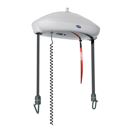
Page 42: Technical Description Of The Ceiling Hoist Robin
8. Technical description of the ceiling hoist ROBIN The Invacare Robin is a two-strap ceiling hoist for max. user weight of 200 kg driven at 24-volts. The motor is powered by batteries charged through the hand control. The Invacare Robin... - Page 44 Sweden & Finland Netherlands Italy INVACARE AB INVACARE B.V. INVACARE MECC SAN S.R.L. Fagerstagatan 9 / Box 66 Celsiusstraat 46 Via dei Pini 62 S-163 91 Spånga NL-6716 BZ Ede I-36016 Thiene (VI) Phone: +46 8 761 70 90...