Invacare Robin User Manual
Hoist
Hide thumbs
Also See for Robin:
- Service manual (228 pages) ,
- User manual (200 pages) ,
- Installation and technical manual (44 pages)
Table of Contents
Advertisement
Quick Links
Advertisement
Table of Contents

Related Manuals for Invacare Robin


Summary of Contents for Invacare Robin
- Page 1 Invacare® Robin User's Manual...
- Page 3 Identification label and QA-mark are located on the hoist confirming that the finished goods control has approved the hoist. Please read the entire user’s manual before using the hoist. Invacare®EC-Høng A/S is certified according to ISO 9001 and ISO 13485. For and on behalf of Invacare®EC-Høng A/S: Brian Mundeling...
- Page 4 Il vostro nuovo il sollevatore da soffito è marcato CE - ai sensi della Direttiva 93/42/EEC relativa ai dispositivi medici. Il il sollevatore da soffito è stato progettato e costruito con un occhio di riguardo per gli utilizzatori e per i loro assistenti. Invacare®...
-
Page 5: Table Of Contents
Table of contents Purpose and application ........7 1.1 Manufacturer: . - Page 6 Technical specifications ........27 8.1 Symbols............. 27 8.2 Installation options of the charger IP41/IP67 .
-
Page 7: Purpose And Application
1. Purpose and application 1.1 Manufacturer: Invacare® EC-Høng A/S Østergade 3 DK - 4270 Høng Tel. + 45 58 85 27 22 Fax. + 45 58 85 43 86 1.2 Purpose and application Purpose Robin is a ceiling mounted hoist, meeting the requirements for hospitals, housing for the elderly, institutions and private homes. Robin is intended for moving clients weighing a maximum of 200 kg including clothing, hoist sling and other accessories. The hoist is designed for indoor use in normal temperatures and humidity. If you wish to use the hoist in any other environment, contact Invacare® for advice and instructions. Use of the hoist for purposes other than transfer of people is not advised and is undertaken at ones own risk. Conditions It is a condition of sale that the purchaser of the ceiling hoist must receive training from Invacare® personnel or an authorised dealer. When the Robin ceiling hoist is used in an institution or in a nursing home, it should always be operated by specially trained staff, and used in recommended track. systems. The track system must be installed by Invacare® personnel or an authorised dealer. Seated to seated transfer During a seated transfer e.g. from a wheel chair, the Robin should be positioned close to the person to be lifted. The suspension hooks should ideally be positioned level with the chest and ideally no further than over the middle of the thigh. Place the suspension hooks parallel with the user’s shoulders. See picture. The sling may now be attached to the suspension hooks. For placement of the sling, see section »Placement of the sling«. -
Page 8: Important/Warnings
Placement of sling The sling straps are to be hooked in pairs (one from the back and one from the leg) on their own suspension hook. (Attachment of the sling is described in the respective user manual, the text and picture below is only a principle explanation). With the person to be lifted in sitting position, the sling is placed behind the user’s back, e.g. between the back support of the chair and the user. The client should not sit on the sling. The leg straps are guided forward along the outside of the thigh and in under the thigh between the knee and the hip joint. The leg straps are crossed between each other in front of the user. All four sling straps are now ready to be mounted into the suspension hooks. When the client is lying down, he/she should be log rolled onto their side. Position the sling in such a way that the upper edge is in line with the crown of the head. The user is then repositioned onto his/her back and log rolled in the opposite direction. The sling is then rolled to be flat under the user when he/she is rolled onto his/her back. The leg straps are then guided in under the thigh bone and crossed in between each other. All four (six) sling straps are now ready to be attached. If there is doubt as to the use of the sling, please contact Invacare®. 1.3 Important/warnings • Read the entire manual before using Robin • Robin’s max. load of 200 kg must not be exceeded. • If accessories are rated with a lower load than 200 kg, this determines Robin’s maximum load. • Robin must only be used to move a patient. • Robin must not be used where there is a risk of contact with water. • If the Robin is damaged, it must be taken out of use. Call your local Invacare® dealer or Invacare’s service department. • The cord for emergency stop/emergency lowering is to be adjusted so it is within the user’s range. Risks when using the hoist: Risk of entrapment between hook and hook housing. -
Page 9: Sling's
Use only CE-marked sling’s with a rated load equal to or lower than that of the Robin’s max load. The sling must be suitable for 2 or 4 point spreader bars (please look at Invacare’s brochure concerning slings), i.e. with sewn lifting loops that can be mounted onto a 2 or 4 point spreader bars. 1.5 Unpacking and preparation Perform a visual inspection of Robin . If the packaging is damaged upon arrival, Robin parts must be thoroughly examined for visible damage or defects. If there is any suspicion of damage, Robin must not be used before qualified service personnel or service technicians have approved the hoist. It is to be expected, that the hoist´s battery is discharged on account of self-discharge. The hoist must therefore be charged for up to 2 hours before first time usage, refer to section »Charging«. The following is to be included in the package: 1. Robin 2. Hand control. 3. Quick guide. (The charging unit must be ordered separately; part no.: 1446317). 1.6 Installing the charging station The charging unit should be attached to the wall, or the most practical place, within reach of a socket outlet, to park the hoist when not in use. It is important to make sure that the hand control can be readily placed into the charger holder when being charged. Therefore place the charger at a maximum distance of 85 cm under the rail in which the hoist is mounted. It is important to make sure that there is access to the mains where the charger is placed. To mount the charger:, first insert wall fitting with 2 screws, then connect the cable from the charger to the actual holder, and press the holder onto the mounted wall support. The wall support for the charger must be mounted with three screws under the holder and at a distance that suits the length of the charger cable. Connect the charger to the socket outlet and check that it is operational. -
Page 10: Hoist System Installation
1.7 Hoist system installation Prior to fitting the hoist, ensure that the hoist trolley is mounted. Remove the end stop that is attached to the rail track. The trolley can then be inserted into the rail. (It is unimportant which way the trolley is facing). The end stop must then be reinstalled. See picture. When mounting Robin , locate the hoist trolley at the Ø 32 mm round recess in the rail. See picture. Lift the hoist and push the suspension pin through the hoist trolley. Turn the hoist 90 degrees to the rail’s longitudinal direction and place it as shown below. (Note: Support the hoist while turning). See picture. If Robin is correctly mounted into the trolley, it is now possible to pull the trolley back and forth along the rail. If there is excessive resistance, or if the trolley unintentionally rolls by itself due to imbalance in the rail suspensions, adjust the friction brake using a 4 mm Allen key. See picture. When the system is installed, the hand control must be connected, and the cord for the emergency stop/lowering must be adjusted so it is within the user’s reach. The system must be inspected before use; see section »Before first time use«. Robin is now ready to be used in the EC-Track system. When using Robin in other rail systems, an alternative trolley must be used. Contact Invacare® for information regarding approved systems. -
Page 11: Inspection
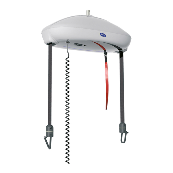
2. Inspection 2.1 Approvals The Robin ceiling hoist has been tested and approved in accordance with Lift standard EN/ISO 10535, and is TÜV approved. The hoist is CE-marked in accordance with the medical directive and standard EN/ISO 10535. 2.2 Before first-time use Before first use, all features of the hoist system must be inspected by a authorised Invacare® installer. The hoist is not intended to be used together with any other MEDICAL ELECTRICAL EQUIPMENT, meaning that the patient must not be connected to any other MEDICAL ELECTRICAL EQUIPMENT during transfer with the Robin hoist. 3. Description of functions 3.1 Description of the hoist´s main parts Control button UP Control button DOWN Connection for hand control Connection for emergency battery Indicator light Hand control Lifting straps Retainer for... -
Page 12: Operation
FUNCTIONS ON THE UPPER SIDE 1. Suspension pin for connecting the hoist to the hoist trolley. 2. Finger screw for dismounting the top section. 3.2 Operation Operating forces of buttons: Max. 5 N Down Hand control and indicator light Robin is activated when the hand control buttons are pressed. The blue indicator light illuminates when Robin is in use, and turns off automatically after approx. 30 seconds. The hoist is lifted and lowered by operating the hand control. The control buttons on the underside of the hoist may also be used for this purpose. The control buttons work independently of the hand control. Note: The buttons must be depressed in the middle in order to ensure correct function, which is best obtained as shown in the pictures. The hoist will automatically run at high speed upwards as well as downwards, when it is not loaded. The straps must be straight to ensure that they feeds into the apertures correctly. The straps are held taught by the weight of the hooks, therefore the lifting straps should be freely suspended when the unloaded hoist is running upwards and downwards. When the hoist is loaded with a weight of more than 10 kg, the speed will automatically be lowered to a safe level when moving in both directions. Robin has a built-in soft start, ensuring a more comfortable lifting and lowering movement of the user. Transport/running in the rail system The empty hoist can be moved along the rail system by pulling the two lifting straps. The hand control must not be used to pull the hoist along. During a transfer, the carer should gently push or pull the client sitting in the sling. -
Page 13: Safety Guidelines
Emergency stop If the hoist straps´ moves unintentionally upwards or downwards, pull the »emergency stop« chord. When the emergency stop is activated, the hoist will not operate. If the emergency stop button is pushed up, the hoist will be ready for use again. Emergency lowering The emergency lowering feature can be used in order to lower a client to the transfer surface if the hoist has become inoperable. Emergency lowering is operated by continuously pulling the cord. When the emergency lowering function is activated, all end stops and security functions are deactivated. It is thereby possible to wind up the lifting straps back up, when activating the emergency lowering for prolonged periods. Strap securing/pinch protection If the lifting straps are guided incorrectly in and out of the hoist, i.e. if the straps has become twisted, the hoist will automatically turn off. Note: When attaching the sling to the hooks, and the straps are twisted, the straps will rotate and stretch out, thus ensuring trouble-free operation. The pinch protection feature automatically turns off the hoist, if a client unintentionally traps his/her hand in the lifting strap during a lift. The hoist will stop immediately when the hand makes contact with the strap inlet. If Robin is loaded with a weight of more than 200 kg, the hoist will automatically turn off to safeguard against overloading. Electromagnetic interference between the hoist and other electrical products can occur. To reduce or eliminate such electromagnetic interference, increase the distance between the hoist and the products or switch off the products! All installations must comply with the national rules and standards. Use only approved installation components. At every point of suspension, the roof/ceiling structure must be able to absorb a load of at least 300 kg. 3.4 Charging A sound indicator and the flashing indicator light signals when the hoist needs to be charged. The hoist must be moved along the rail system and parked nearby the wall mounted charger. Attach the hand control to the charger unit. LED on the charger indicates that charging is taking place. We recommend parking the hoist in the charging position when not in use. LED indication Function Function duration... -
Page 14: Charging An Emergency Battery
Note! It is not possible to use the hoist whilst charging the battery. If the sound indicator of the Robin beeps, and the blue function lights flash after Robin that has been fully charged and has been in use for only a short period of time, the battery may be ready to be replaced by a new one. See section »7.2 Battery«. Another possible option could be that the battery needs to be excercised. See section »3.6 Battery maintanance«. 3.5 Charging an emergency battery The emergency battery package is charged by placing the plug in the charger socket. A special adapter is necessary. The LED light turns green to indicate the unit is fully charged (appox. charging time 2 hours). 3.6 Battery maintanance If the sound indicator of the Robin beeps, and the blue function lights flashes after the hoist has been fully charged and has been in use for only a short period of time, the battery might need to be exercised. To enable the battery to be charged fully, it is neccessary to exercise the battery from time to time. Following a long period of storage, it could be neccessery to exercised the battery. It is also suggested that the battery is exercised in situations where Robin Mover is used infrequently, and/or where the hand control is placed in the charger for long periods of time. In this situation, there will always be capacity enough for a few lifts, but we recommend to exercise the battery as soon as possible afterwards. Exercise of the battery can be done by charging and discharging Robin completely several times. This is done by charging the battery until the light indicator turns green. The hand control is then removed from the charger, and the straps with load are lowered and raised for one minute, with a 10 minutes break, continuing this procedure until the battery is completely discharged (continue even when the sound signal for low power beeps and the blue light flashes). Charge the battery and lower and raise the straps until the battery is decharged again. Repeat this procedure 2-3 times. -
Page 15: Accessories
Charger kit IP67 for hand control, grey (with 0,1/2 m cable, bracket and retainers). 1451911-7035 Charger kit IP67 for hand control, grey (with 0,1/3 m cable, bracket and retainers). 1451912-7035 Charger kit IP67 for hand control, grey (with 1,2/1 m cable, bracket and retainers). 1451913-7035 Charger kit IP67 for hand control, grey (with 1,2/2 m cable, bracket and retainers). 1451914-7035 Charger kit IP67 for hand control, grey (with 1,2/3 m cable, bracket and retainers). 1450290-7035 Clamp for charger for wall mounting (without transformer), bracket and retainers. 1449668-7035 Charger for external battery, grey. 1446269-7012 Distance clamp (Flexiscope). 1488974-7012 4-point spreader bar, 45 cm. 1492967-7012 2-point spreader bar, 35 cm. 1492968-7012 2-point spreader bar, 45 cm. 1485474-7035 Retainer for wall mounted charger. 1449228-7035 Retainer for hand control, strap mounted. 1450289 Gearwheel grease (3 g tube). 1449383-9010 Hoist trolley Inalto/Invacare. 1485183-9010 Room-to room trolley (white) EC-Track. 1485183-9006 Room-to room trolley (grey) EC-Track. 1451620-7012 Extended lifting straps with hooks and emergency lowering strap (extra length must be specified when ordering). 1493132 Ergolet spreader bar with weight scale. 1504765-7012 Stretcher with sling. -
Page 16: Transit Coupling
See drawing A point 1. Then move the Robin and tracking so that the two sections of track line up with each other. See drawing A point 2. B) Press the button on the wall mounted control box. See drawing b point 3. When the tracking is locked in place the green light illuminates and the transfer can be carried out. See drawing B point 4 & 5. C) When the Robin is safely located on the new section of tracking, the button on the control box, can then be pressed again to unlock the two sections of tracking. See drawing C point 6 & 7. D) The green light will then go out, to indicate that the two sections of tracking can be safely moved away from each other. See drawing D point 8 & 9. It is esssential that during the transfer process you locate the Robin Mover as indicated in the above diagrams, this will ensure the safe coupling of the tracking sections. If in doubt , or you experience difficulty in coupling the... -
Page 17: Ec-Gantry
4.3 EC-Gantry The EC-Gantry is used where there is a requirement for a free standing rail system. Height range for EC-Gantry without wheels: 216-251 cm Height range for EC-Gantry with wheels: 195-230 cm The EC-Gantry is available with or without wheels. The wheels of the EC-Gantry must be locked before performing any lift. To increase the height of the EC-Gantry, pull the leg section upward. To decrease the height of the EC-Gantry, pull the handle as indicated above, adjust the EC-Gantry to the desired height and then release the handle to allow the leg section to lock back into place. Wih regards to the safety of the patient, it is recommended that the EC-Gantry is not moved with a patient hanging in the sling. It is important that the EC-Gantry is placed on a level surface with regards to the risk of tipping. Please observe that there is a risk of the patient swinging into the EC-Gantry´s legs. There is a risk of carer stumbling over foot of the EC-Gantry system. There is a risk of tipping if the patient is very unsettled or suffers from spasm in the sling. Never leave a patient in the sling unattended. -
Page 18: Ec-Gantry Traverse
4.3.1 EC-Gantry Traverse The EC-Gantry Traverse is used where there is a requirement for a free room covering standing rail system. Height range for EC-Gantry Traverse : 218-253 cm It is important that the EC-Gantry Traverse is placed on a level surface with regards to the risk of tipping. Please observe that there is a risk of the patient swinging into the Gantry´s legs. There is a risk of tipping if the patient is very unsettled or suffers from spasm in the sling. Never leave a patient in the sling unattended. -
Page 19: Flexiscope
4.4 Flexiscope Scope Flexiscope is used with the Invacare© Robin ceiling hoist in connection with the transfer or moving of disabled patients who require extended distance between the slings shoulder straps. Max. load: 200 kg. Installation Installation of Flexiscope the lifting straps is carried out according to the illustrations. Adjustment Alignment of the width is made by pulling the button A while moving the strap bar B to the desired position. Note! Ensure that the bar is correctly engaged. Maintenance and cleaning Cleaning in connection with daily use: • All painted surfaces can be whiped off with a damp cloth. Only household detergents are allowed. Never use acids, alkalines or solvents such as acetone or cellulose thinner. • Desinfection of Flexiscope - it must be whiped over with officially approved detergents only. • The black cover is removed from Flexiscope and can be mashine washed at 70ºC - do not tumbledry, bleach or dry clean. -
Page 20: Mounting Of 4-Point Spreader Bar
4.5 Mounting of 4-point and 2-point spreader bar • Lower the Robin lifting straps down to a suitable height and mount the spreader bar shown on the illustration below. • Use only the spreader bars produced for Robin. • Ensure that the spreader bar suits the client and the type of lift required. Ensure the spreader bar is correctly mounted before use. -
Page 21: Track Switch, Manual
4.6 Track switch, manual The track switch is used in track systems where a change in direction is required during movement of the patient. The track switch is operated by pulling the cords on either side - this change in direction must be carried out before the client is guided into the drive switch area. The direction is changed, and the hoist will take the direction to the side where the cord is pulled. The track switch is mechanically secured against derailing. -
Page 22: Room To Room Transfer
4.7 Room to room transfer 1. The two hoists are moved as close to the doorway as possible. The sling is attached to hoist A. The lifting straps on hoist A are lowered as far as possible with concideration to the patient´s comfort. 2. The two lifting straps on hoist B are lowered as much as necessary to attach them to the sling. Note! Ensure that the lifting strap hooks are installed correctly. 3. The lifting straps of hoist B are raised while the straps on hoist A are lowered. Continue until the patient is completely suspended by hoist B. 4. The lifting straps on hoist A is now uncoupled from the sling and rewound. Note! Beware of dangeling hooks or hand control. 5. The lifting straps on B are rewound to the desired height. The room to room transfer is now carried out. -
Page 23: Dismounting & Transport
5. Dismounting & transport 5.1 Dismounting When dismounting Robin , please see section »Installation of hoist system«. 5.2 Transport The emergency strap must be pulled, when the Robin motor is demounted from the tracks, for transport or storage, otherwise the Robin can be accidentally activated. See section »6.2 Storage«. During transportation, the hoist must be placed on a soft surface, e.g. a cloth or foam rubber mat. Make sure that Robin remains upright whilst being moved. We recommend using the original packaging for transportation under the following conditions: • Temperature between -30° and +50°C. • Humidity between 10 og 70% RH. • Pressure between 700 og 1.100 hPa. -30 50°C 10 → 70% 700 → 1.100 hPa → -22 122°F → 6. Maintenance & Storage Only Invacare authorised personnel should perform maintenance and service. Daily inspection should be carried out by the carer after reading the manual. Six monthly inspection according to UK LOLER 1998 regulations should be done also. Spare parts list and wiring diagram can be obtained from Invacare®or be down loaded from www. -
Page 24: Service & Lifetime
7. Service & lifetime 7.1 Service & lifetime To ensure the optimal function and safety of Robin, it is important to perform service and maintenance in accordance with the manual. Maintenance must be carried out following national regulations, and at least yearly. According to the Factories Inspectorate regulations, Robin has to undergo an annual service by an Invacare® authorised person. Durability and lifetime expectancy is based on an annual service programme performed by an Invacare® authorised dealer or Invacare®. Robin has an expected lifetime of approx. 10 years. After 10 years use, it must be inspected by qualified personnel before further use. If the hoist is used in localities with increased humidity, a reduction in lifetime must be expected. Spare part list for Robin and EC-Track can be obtained from Invacare®. 7.2 Battery To change battery. If battery replacement is necessary, Robin must be removed from the track system. Please see section »dismounting«. Release the upper part of the hoist by removing two screws. See picture. Remove the battery pack inside the hoist by unplugging the wires, and replace it with a new one. Re attach the upper part of the housing. Important! Use only Invacare®recommended batteries, see section »Accessories«. The battery must be located as shown in picture 7. If the battery housing is damaged, do not use the battery. It is not necessary for an approved service person to carry out the battery change. -
Page 25: Maintenance
Use of emergency batteries Should the need for immediate use of Robin arise at a time when the hoist has a discharged battery, a Invacare® emergency battery can be used. This battery is connected to the underside of the motor, hanging freely during client transportation. Use the emergency battery only when absolutely necessary. Always recharge this battery after use, please see section »Charging«. The emergency battery is an accessory that can be ordered from your Invacare® dealer, see section »Accessories«. Important! Use only Invacare®recommended emergency batteries. 7.3 Maintenance .3 Maintenance When performing annual or regular maintenance, all parts designed to carry load must be tested at maximum capacity (both hoist and track system). All safety features must be checked. A function test of the system with 1.5 x maximum load must also be performed. During the service, all parts that is exchanged and all work carried out, must be documented. The worn and defective parts must be replaced with new spare parts from Invacare. Inspection of the hoist and track system must be carried out by a qualified Invacare® authorised dealer. To record the details, please use the service schedule on page 30. EC-Track system inspection • All bolts/fixtures in walls and ceiling must be checked and re tightened if necessary. • The end stop on the tracks is checked, adjusted if necessary and re tightened. • Systems with track connections should be checked and realigned if the connection has become mis-aligned during use. • Test the trolley and the traverse trolley. Check for noise and smooth movement. • For a traverse system, check all functions and connections. •... -
Page 26: Troubleshooting
Electrical parts: • Check the wiring for damage and secure connections. • Check the micro switches for clamping and their mechanical function. • Check the hand control for damage and function. Make sure that the hand control is securely connected. • Check the emergency stop/lowering. 7.4 Troubleshooting Service and maintenance of Robin must only be performed by personnel who have received the necessary instruction and training. Symptom Possible cause Action The hoist is not responding 1) The emergency stop is 1) Depress the emergency stop correctly when pressing the hand activated. button. control buttons, and the up/down 2) The battery is discharged. 2) Put the hoist on charge or use buttons on the hoist are not the emergency battery. functioning. 3) The fuse is blown. 3) Replace the fuse. The hoist is not responding cor- 1) The hand control is not 1) Secure the plug. rectly when pressing the hand connected correctly. control buttons, but the up/down 2) The hand control is defect. 2) Replace the hand control. buttons on the hoist are functioning. -
Page 27: Technical Specifications
8. Technical specifications . Technical specifications Dimensions (HxBxD) 19x47x25 cm. Max. lifting capacity 200 kg. Number of lifts per charge 65 lifts of 0.5 m with 80 kg. Lifting velocity at 200 kg load 2 cm/s. Max lifting interval 250 cm. Height from celling to sling hook 41 cm. Total weight without sling 7 kg. Electrical connection of charger 230V AC 50Hz Voltage/current between charger/hoist 24V DC 900mA / 50mA. Charging time (with 2 Ah battery) Max 2 hours Battery 20 pcs. 1.2V / 2.0 Ah 4/5 SC NiMH Intermittence Sound pressure 50-55 dB (A) Protection class IPX4 8.1 Symbols Warning. SWL (Safe Working Load) = Max. load (patient + sling + other accessories). = 200 kg Class II equipment. Type B equipment - patient not separated from ground. -
Page 28: Installation Options Of The Charger Ip41/Ip67
8.2 Installation options of the charger IP41/IP67 8.2.1 IP41 May not be used in a wetroom environment. 8.2.2 IP67 The charger is designed according to IP67, and can therefore be used in wet locations according to these illustrations: Bath tub Shower basin Bath tub Bath tub Shower without basin Shower with fixed partition Shower head Shower head Installation of the charger is recommended in zone 2 and 3. -
Page 29: Disposal
9. Disposal This product has been supplied from an environmentally aware manufacturer that complies with the Waste Electrical and Electronic Equipment (WEEE) Directive 2002/96/CE This product may contain substances that could be harmful to the environment if disposed of in places (landfills) that are not appropriate according to legislation. The »crossed out wheelie bin« symbol is placed on this product to encourage you to recycle wherever possible. Please be environmentally responsible and recycle this product through your recycling facility at its end of life. All electrical parts must be removed and disposed of as electrical components. Plastic parts must be recycled or incinerated. Steel- and aluminium parts must be disposed of as metal scrap. Batteries: Local and national regulations for environmental recycling must be followed. Batteries must always be delivered to an approved collection place. Disposal must always follow the relevant local laws and regulations for waste and scrap. -
Page 30: Service Schedule
10. Service schedule Service and maintenance of the hoist must be carried out only by trained/experienced personnel Personnel hoist serial number: __________________________________ Inspection point: Date: Inspection of the track system All bolts/fixtures to wall and ceiling must be checked and re-tightened if necessary. End stops on the tracks must be checked, moved if necessary and re-tightened. Systems with track connections should be checked and re-aligned if the connection has become mis-aligned during use. Check trolley and traverse trolley. Check trolley wheels for smooth movement and abnormal noise. Check friction break adjustment on trolleys. Adjust if necessary. - Page 32 Sweden & Finland Netherlands Italy INVACARE AB INVACARE B.V. INVACARE MECC SAN S.R.L. Fagerstagatan 9 / Box 66 Celsiusstraat 46 Via dei Pini 62 S-163 91 Spånga NL-6716 BZ Ede I-36016 Thiene (VI) Phone: +46 8 761 70 90...