Table of Contents

Related Manuals for York YST


Summary of Contents for York YST
- Page 1 STeaM Turbine CenTrifugal liquid ChillerS operaTionS Manual Supersedes: 160.67-O1 (114) Form: 160.67-O1 (415) Model YST STeaM Turbine drive CenTrifugal liquid Chiller WiTh opTivieW ConTrol CenTer deSign level f and g LD12189 Issue Date: April 1, 2015...
- Page 2 FORM 160.67-O1 ISSUE DATE: 4/1/2015 iMporTanT! READ BEFORE PROCEEDING! general SafeTY guidelineS This equipment is a relatively complicated apparatus. which it is situated, as well as severe personal injury or During rigging, installation, operation, maintenance, death to themselves and people at the site. or service, individuals may be exposed to certain com- This document is intended for use by owner-authorized ponents or conditions including, but not limited to:...
- Page 3 Manual deSCripTion forM nuMber Installation - Units Manufactured Before 12/06 160.67-N1 Installation - Units Manufactured. After 12/06 160.67-N2 Unit Operation & Maintenance 160.67-O2 Wiring Diagram - Model YST 160.67-PW6 Renewal Parts - Control And Instrumentation - Model YST 160.67-RP2 JOHNSON CONTROLS...
- Page 4 FORM 160.67-O1 ISSUE DATE: 4/1/2015 noMenClaTure The model number denotes the following characteristics of the unit. YST vf vd J4 - Kd71750090 - 14 - 0.6 - 33192C - f S Chiller Model Special (Mandatory) Evaporator Code Design Level Condenser Code...
-
Page 5: Table Of Contents
Steam And Condensate Flow ......................... 12 SeCTion 2 - opTivieW ConTrol CenTer inTroduCTion ................15 Interface Conventions ............................ 17 Analog Input Ranges - York Microboard ......................19 Analog Input Ranges - Frick I/O Board ......................20 Home Screen ..............................21 Refrigeration System Screen ......................... 24 Evaporator Screen ............................ - Page 6 FORM 160.67-O1 ISSUE DATE: 4/1/2015 Table of ConTenTS (ConT'd) History Screen .............................. 114 Display Only ..............................114 History Details Screen ..........................116 Security Log Screen ............................. 117 Security Log Details Screen ......................... 119 Custom View Screen ............................ 120 Custom View Setup Screen.......................... 121 Trend Screen ..............................
- Page 7 FORM 160.67-O1 ISSUE DATE: 4/1/2015 liST of figureS figure 1 - Model YST Chiller ..........................9 figure 2 - Refrigerant Flow-Thru ..........................10 figure 3 - Detail A – Compressor Pre-Rotation Vanes ..................11 figure 4 - Steam And Condensate Flow ......................13 figure 5 - Optiview Control Center........................16...
- Page 8 FORM 160.67-O1 ISSUE DATE: 4/1/2015 liST of figureS (ConT'd) figure 55 - Sample Printout (Status)........................154 figure 56 - Sample Printout (Setpoints) ......................156 figure 57 - Sample Printout (Sales Order)......................158 figure 58 - Sample Printout (History).........................159 figure 59 - Sample Printout (Security Log Report) ....................161 figure 60 - Sample Printout (Trend Data New Or Existing Points) ..............
-
Page 9: Section 1- Description Of System And Fundamentals Of Operation
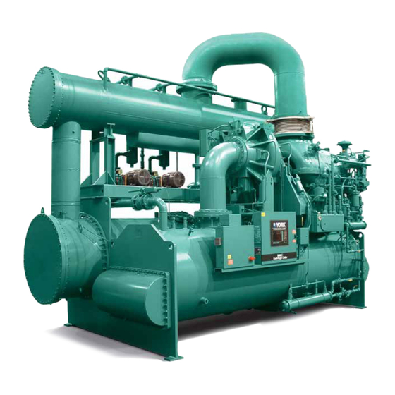
The control panel includes a color liquid crystal display (LCD) surrounded by “soft” keys which are redefined The YORK Model YST Chiller is commonly applied based on the screen displayed at that time, mounted to large air conditioning systems, but may be used on in the middle of a keypad interface and installed in a other applications. -
Page 10: Refrigerant Flow Diagram
FORM 160.67-O1 SECTION 1- DESCRIPTION OF SYSTEM AND FUNDAMENTALS OF OPERATION ISSUE DATE: 4/1/2015 refrigeranT floW diagraM LEGEND HIGH PRESSURE VAPOR COMPRESSOR HIGH PRESSURE LIQUID REFIGERANT LOW PRESSURE LIQUID REFIGERANT LOW PRESSURE VAPOR DISCHARGE HOT GAS BYPASS VALVE CONDENSER SUCTION ELIMINATOR SUB-COOLER EVAPORATOR... -
Page 11: Capacity Controls
FORM 160.67-O1 SECTION 1- DESCRIPTION OF SYSTEM AND FUNDAMENTALS OF OPERATION ISSUE DATE: 4/1/2015 CapaCiTY ConTrolS During part load operation at off design conditions, the chiller capacity is reduced to maintain a constant leaving chilled liquid temperature by first decreasing the speed, closing the compressor pre-rotation vanes (PRV) (See Figure 3 on page 11), then opening the Hot Gas Bypass valve. -
Page 12: Steam And Condensate Flow
FORM 160.67-O1 SECTION 1- DESCRIPTION OF SYSTEM AND FUNDAMENTALS OF OPERATION ISSUE DATE: 4/1/2015 STeaM and CondenSaTe floW (See Figure 4 on page 13) The primary function of a steam turbine is to convert condenser. The steam condenser tubes are kept cool by thermal energy into the mechanical energy required to the circulation of liquid from the refrigerant condenser rotate the compressor. -
Page 13: Figure 4 - Steam And Condensate Flow
FORM 160.67-O1 SECTION 1- DESCRIPTION OF SYSTEM AND FUNDAMENTALS OF OPERATION ISSUE DATE: 4/1/2015 STeaM and CondenSaTe floW diagraM TURBINE EXHAUST NON-CONDENSIBLE OUTLET (TO VACUUM PUMP) RECIRCULATION VALVE STEAM CONDENSER HIGH PRESSURE STEAM INLET HOTWELL SPOOL PIECE OVERBOARD VALVE HOTWELL CONDENSATE PUMP GOVERNOR... - Page 14 FORM 160.67-O1 SECTION 1- DESCRIPTION OF SYSTEM AND FUNDAMENTALS OF OPERATION ISSUE DATE: 4/1/2015 THIS PAGE INTENTIONALLY LEFT BLANK. JOHNSON CONTROLS...
-
Page 15: Section 2 - Optiview Control Center Introduction
FORM 160.67-O1 ISSUE DATE: 4/1/2015 SeCTion 2 - opTivieW ConTrol CenTer inTroduCTion The YORK OptiView Control Center is furnished as mounted liquid pump motor starter control circuits standard on each chiller and provides the ultimate in (supplied by others) and controls installed on the chill- efficiency, automation, monitoring, data recording, er. -
Page 16: Figure 5 - Optiview Control Center
FORM 160.67-O1 SECTION 2 - OPTIVIEW CONTROL CENTER INTRODUCTION ISSUE DATE: 4/1/2015 opTivieW ConTrol CenTer LD09284 figure 5 - opTivieW ConTrol CenTer The OptiView Control Center display is highlighted by the middle position, this is considered the RUN state. a full screen graphics display. This display is nested When toggled to the left-most position, it is considered within a standard keypad, and is surrounded by “soft”... -
Page 17: Interface Conventions
FORM 160.67-O1 SECTION 2 - OPTIVIEW CONTROL CENTER INTRODUCTION ISSUE DATE: 4/1/2015 inTerfaCe ConvenTionS overvieW The new graphical display on each control panel al- lowed to change any values. To change any values, the lows a wide variety of information to be presented to user must return to the Home Screen (shown by de- the user. - Page 18 FORM 160.67-O1 SECTION 2 - OPTIVIEW CONTROL CENTER INTRODUCTION ISSUE DATE: 4/1/2015 Pressing the ▲ key, sets the entry value to the de- Home (Page 20) fault for that setpoint. Pressing the ▼ key, clears Refrigeration System (page 24) the present entry. The ◄ key is a backspace key Evaporator (page 26) and causes the entry point to move back one space. Condenser (page 28) If the dialog box begins with “SELECT”, use the Compressor (page 30) ◄ and ► keys to select the desired value.
-
Page 19: Analog Input Ranges - York Microboard
FORM 160.67-O1 SECTION 2 - OPTIVIEW CONTROL CENTER INTRODUCTION ISSUE DATE: 4/1/2015 analog inpuT rangeS - YorK MiCroboard The following tables indicate the valid display range mum or maximum value, respectively. Inputs shown for each of the analog input values. In the event that the... -
Page 20: Analog Input Ranges - Frick I/O Board
FORM 160.67-O1 SECTION 2 - OPTIVIEW CONTROL CENTER INTRODUCTION ISSUE DATE: 4/1/2015 analog inpuT rangeS - friCK i/o board engliSh range MeTriC range friCK i/o board analog inpuT high uniTS high uniTS Turbine Shaft End Horizontal Vibration (Optional) Mils 127.0 Micrometers Turbine Shaft End Vertical Vibration (Optional) Mils... -
Page 21: Home Screen
FORM 160.67-O1 SECTION 2 - OPTIVIEW CONTROL CENTER INTRODUCTION ISSUE DATE: 4/1/2015 hoMe SCreen LD09257 noTe: OptiView Control Center Screens shown may NOT represent the exact screens according to the software version utilized. ™ figure 6 - HOME SCREEN operating hours overvieW Displays the cummulative operating hours of the chill- When the chiller system is powered on, the above de-... - Page 22 FORM 160.67-O1 SECTION 2 - OPTIVIEW CONTROL CENTER INTRODUCTION ISSUE DATE: 4/1/2015 prograMMable Message Clear Access Level Required: SERVICE login Access Level Required: VIEW When certain safety or cycling conditions have been detected and the chiller has been shutdown, the main The OptiView Panel restricts certain operations based status display of the chiller will continue to display a on password entry by the operator.
- Page 23 FORM 160.67-O1 SECTION 2 - OPTIVIEW CONTROL CENTER INTRODUCTION ISSUE DATE: 4/1/2015 will close to the calculated anti-surge minimum vane Condenser position. While the vanes are closing and the head is A detailed view of all condenser parameters, including decreasing, the speed will continue to ramp down to control of the liquid level functions.
-
Page 24: Refrigeration System Screen
FORM 160.67-O1 SECTION 2 - OPTIVIEW CONTROL CENTER INTRODUCTION ISSUE DATE: 4/1/2015 refrigeraTion SYSTeM SCreen LD09258 noTe: OptiView Control Center Screens shown may NOT represent the exact screens according to the software version utilized. ™ figure 7 - refrigeraTion SYSTeM SCreen overvieW evaporator pressure This screen gives a general overview of common chill-... - Page 25 FORM 160.67-O1 SECTION 2 - OPTIVIEW CONTROL CENTER INTRODUCTION ISSUE DATE: 4/1/2015 oil pressure prograMMable Displays the pressure differential between the high side None oil pressure transducer (output of oil filter) and the low navigaTion side oil pressure transducer (compressor housing). The displayed value includes offset pressure derived from home auto-zeroing during the system prelube.
-
Page 26: Evaporator Screen
FORM 160.67-O1 SECTION 2 - OPTIVIEW CONTROL CENTER INTRODUCTION ISSUE DATE: 4/1/2015 evaporaTor SCreen 00301VIP noTe: OptiView Control Center Screens shown may NOT represent the exact screens according to the software version utilized. ™ figure 8 - evaporaTor SCreen leaving Chilled liquid Temperature overvieW Displays the temperature of the liquid as it leaves the This screen displays a cutaway view of the chiller... - Page 27 FORM 160.67-O1 SECTION 2 - OPTIVIEW CONTROL CENTER INTRODUCTION ISSUE DATE: 4/1/2015 leaving Chilled liquid Temperature Setpoints setpoint (see the Remote Leaving Chilled Liquid Tem- - Shutdown perature Setpoint Range description above). Addition- ally, MicroGateway (in ISN Remote mode) can define Displays the Leaving Chilled Liquid Temperature at the setpoint through a serial data stream.
- Page 28 FORM 160.67-O1 SECTION 2 - OPTIVIEW CONTROL CENTER INTRODUCTION ISSUE DATE: 4/1/2015 brine low evaporator Cutout refrigerant (enabled / disabled) Access Level Required: SERVICE Access Level Required: SERVICE When an Evaporator Refrigerant Sensor has been in- This value is only available in Brine mode. It allows stalled it must be enabled via this toggle before the the user to specify the Evaporator Pressure at which a system will utilize the new, enhanced resolution input.
-
Page 29: Condenser Screen
FORM 160.67-O1 SECTION 2 - OPTIVIEW CONTROL CENTER INTRODUCTION ISSUE DATE: 4/1/2015 CondenSer SCreen 00302VIP noTe: OptiView Control Center Screens shown may NOT represent the exact screens according to the software version.utilized. ™ figure 9 - CondenSer SCreen overvieW Small Temperature difference This screen displays a cutaway view of the chiller con- Displays the difference between the Condenser Refrig- denser. - Page 30 Home Displays the current operation of the Enhanced Zone Access Level Required: VIEW Level Control. Service Technicians refer to YORK Causes an instant return to the Home Screen. Service Manual 160.67-M3 for additional information on the operation of this control.
-
Page 31: Compressor Screen
FORM 160.67-O1 SECTION 2 - OPTIVIEW CONTROL CENTER INTRODUCTION ISSUE DATE: 4/1/2015 CoMpreSSor SCreen 00466VIP noTe: OptiView Control Center Screens shown may NOT represent the exact screens according to the software version utilized. ™ figure 10 - CoMpreSSor SCreen overvieW This screen displays a cutaway view of the chiller com- (3) second period beginning ten (10) seconds into the pressor, revealing the impeller, and shows all condi-... - Page 32 FORM 160.67-O1 SECTION 2 - OPTIVIEW CONTROL CENTER INTRODUCTION ISSUE DATE: 4/1/2015 high Speed Thrust bearing proximity Compressor. The Accelerometer signal is converted to differential a 4-20 mA signal by a Transmitter in the Turbine Box and connected to the Frick Analog I/O Board in the Displays the distance between the high-speed thrust Control Center.
- Page 33 FORM 160.67-O1 SECTION 2 - OPTIVIEW CONTROL CENTER INTRODUCTION ISSUE DATE: 4/1/2015 pre-rotation vane Calibration Access Level Required: SERVICE Access Level Required: VIEW Only available if the chiller is stopped. Moves to the A detailed view of the information pertinent to the sub-screen allowing calibration of the Pre-rotation Variable Geometry Diffuser (VGD) operation.
-
Page 34: Proximity Probe Calibration Screen
FORM 160.67-O1 SECTION 2 - OPTIVIEW CONTROL CENTER INTRODUCTION ISSUE DATE: 4/1/2015 proxiMiTY probe CalibraTion SCreen 00305VIP noTe: OptiView Control Center Screens shown may NOT represent the exact screens according to the software version utilized. ™ figure 11 - proxiMiTY probe CalibraTion SCreen overvieW oil pressure This screen displays a cutaway view of the chiller com-... - Page 35 FORM 160.67-O1 SECTION 2 - OPTIVIEW CONTROL CENTER INTRODUCTION ISSUE DATE: 4/1/2015 accept Calibration navigaTion This option only becomes available after the calibra- home tion sequence is complete. Access Level Required: VIEW fault acknowledge Causes an instant return to the Home Screen. This option is only displayed if a fault is present.
-
Page 36: Pre-Rotation Vanes Calibration Screen
Cancel Calibration This option only becomes available after calibration diSplaY onlY has started. Service Technicians refer to YORK Service Manual 160.67-M3 for an explanation of this setpoint. pre-rotation vanes opening (led) Indicates the vanes are opening. navigaTion... -
Page 37: Oil Sump Screen
FORM 160.67-O1 SECTION 2 - OPTIVIEW CONTROL CENTER INTRODUCTION ISSUE DATE: 4/1/2015 oil SuMp SCreen 00309VIP noTe: OptiView Control Center Screens shown may NOT represent the exact screens according to the software version utilized. ™ figure 13 - oil SuMp SCreen oil pump run output (led) overvieW Indicates whether the Oil Pump is being commanded... - Page 38 FORM 160.67-O1 SECTION 2 - OPTIVIEW CONTROL CENTER INTRODUCTION ISSUE DATE: 4/1/2015 pulldown Time remaining variable Speed oil pump Speed Control: (variable Speed oil pump only) Displays the time remaining until the user-programmed Access Level Required: SERVICE Oil Pressure setpoint is used. This key allows the user to specify a fixed manual variable Speed oil pump Control Mode speed at which the VSOP will run.
-
Page 39: Variable Geometry Diffuser (Vgd) Screen
FORM 160.67-O1 SECTION 2 - OPTIVIEW CONTROL CENTER INTRODUCTION ISSUE DATE: 4/1/2015 variable geoMeTrY diffuSer (vgd) SCreen LD09502 noTe: OptiView™ Control Center Screens shown may NOT represent the exact screens according to the software version utilized. figure 14 - variable geoMeTrY diffuSer (vgd) SCreen vgd Count overvieW Displays the number of times the Stall Detector Board... -
Page 40: [Vgd] Hold (Manual)
FORM 160.67-O1 SECTION 2 - OPTIVIEW CONTROL CENTER INTRODUCTION ISSUE DATE: 4/1/2015 diffuser gap Control Mode navigaTion Indicates whether the VGD is under manual or auto- home matic control. Access Level Required: VIEW prograMMable Causes an instant return to the Home Screen. [vgd] open (Manual) Compressor Access Level Required: SERVICE... -
Page 41: Variable Geometry Diffuser Setpoints Screen
FORM 160.67-O1 SECTION 2 - OPTIVIEW CONTROL CENTER INTRODUCTION ISSUE DATE: 4/1/2015 variable geoMeTrY diffuSer SeTpoinTS SCreen LD09503 noTe: OptiView Control Center Screens shown may NOT represent the exact screens according to the software version utilized. ™ figure 15 - variable geoMeTrY diffuSer (vgd) SeTpoinTS SCreen vgd Count overvieW Displays the number of times the Stall Detector Board... - Page 42 FORM 160.67-O1 SECTION 2 - OPTIVIEW CONTROL CENTER INTRODUCTION ISSUE DATE: 4/1/2015 Stall dC pressure voltage prv vgd inhibit Displays the DC voltage from the stall pressure trans- (40-100%, default 95) – If the Pre-Rotation Vanes Po- ducer. sition is above this value, the VGD control is disabled and the VGD is pulsed open according to the Open Time remaining Pulse setpoint.
-
Page 43: Steam System Screen - Manual Start
FORM 160.67-O1 SECTION 2 - OPTIVIEW CONTROL CENTER INTRODUCTION ISSUE DATE: 4/1/2015 STeaM SYSTeM SCreen - Manual STarT LD09259 noTe: OptiView™ Control Center Screens shown may NOT represent the exact screens according to the software version utilized. figure 16 - STeaM SYSTeM SCreen - Manual STarT Speed Setpoint overvieW Displays the current speed setpoint that is dictated by... - Page 44 FORM 160.67-O1 SECTION 2 - OPTIVIEW CONTROL CENTER INTRODUCTION ISSUE DATE: 4/1/2015 inlet pressure nozzle #1 Solenoid (led) Displays the steam pressure measured at the inlet of Illuminates when the Turbine Nozzle Valve #1 Air the turbine. Dump Solenoid Valve is energized to open that turbine nozzle valve.
- Page 45 FORM 160.67-O1 SECTION 2 - OPTIVIEW CONTROL CENTER INTRODUCTION ISSUE DATE: 4/1/2015 run at rated Turbine Access Level Required: OPERATOR Access Level Required: VIEW This key is used to initiate the ramp up to rated speed A detailed view of all the turbine lube system parame- only if MSSP4-Turbine Start Mode is set for Manual ters and other status displays pertinent to the operation on the Configuration Screen 1.
-
Page 46: Steam System Screen - Auto Start
FORM 160.67-O1 SECTION 2 - OPTIVIEW CONTROL CENTER INTRODUCTION ISSUE DATE: 4/1/2015 STeaM SYSTeM SCreen - auTo STarT LD09259 noTe: OptiView Control Center Screens shown may NOT represent the exact screens according to the software version utilized. ™ figure 17 - STeaM SYSTeM SCreen - auTo STarT Steam flow overvieW Displays the rate of steam flowing through the turbine. - Page 47 FORM 160.67-O1 SECTION 2 - OPTIVIEW CONTROL CENTER INTRODUCTION ISSUE DATE: 4/1/2015 governor valve bypass Solenoid (led) Displays the present control signal being sent to the Illuminates when the Steam Inlet Slow Roll Bypass Air analog output controlling the pneumatically actuat- Dump Solenoid Valve is energized to allow the valve to ed turbine governor valve.
- Page 48 FORM 160.67-O1 SECTION 2 - OPTIVIEW CONTROL CENTER INTRODUCTION ISSUE DATE: 4/1/2015 Steam ring drain Solenoid (led) Turbine Illuminates when the digital output controlling the Access Level Required: VIEW Turbine Steam Ring Drain Solenoid Valve is energized A detailed view of all the turbine lube system param- to open the drain line and allow any water that may eters and other status displays pertinent to the operation have condensed inside the Turbine to drain out.
-
Page 49: Turbine Screen
FORM 160.67-O1 SECTION 2 - OPTIVIEW CONTROL CENTER INTRODUCTION ISSUE DATE: 4/1/2015 Turbine SCreen LD09264 noTe: OptiView Control Center Screens shown may NOT represent the exact screens according to the software version utilized. ™ figure 18 - Turbine SCreen MPU #2 Speed overvieW This screen displays information for the turbine lube Access Level Required: SERVICE... - Page 50 FORM 160.67-O1 SECTION 2 - OPTIVIEW CONTROL CENTER INTRODUCTION ISSUE DATE: 4/1/2015 Shaft horizontal vibration oil Temperature Displays the movement of the turbine shaft on the shaft Displays the temperature of the supply oil leaving end of the turbine. It is measured by a proximity probe the oil cooler down stream of the temperature control installed at approximately 45 degrees from the verti- valve.
- Page 51 FORM 160.67-O1 SECTION 2 - OPTIVIEW CONTROL CENTER INTRODUCTION ISSUE DATE: 4/1/2015 prograMMable navigaTion Manual Pump (Disabled/Enabled) Home Access Level Required: OPERATOR Access Level Required: VIEW This key puts the auxiliary oil pump control in the Causes an instant return to the Home Screen. Manual Mode and forces it to RUN.
-
Page 52: Condensate Screen
FORM 160.67-O1 SECTION 2 - OPTIVIEW CONTROL CENTER INTRODUCTION ISSUE DATE: 4/1/2015 CondenSaTe SCreen LD09265 noTe: OptiView Control Center Screens shown may NOT represent the exact screens according to the software version utilized. ™ figure 19 - CondenSaTe SCreen low level Switch (open/Closed) overvieW Displays the status of the Hotwell Condensate Low This screen displays information pertaining to the... - Page 53 FORM 160.67-O1 SECTION 2 - OPTIVIEW CONTROL CENTER INTRODUCTION ISSUE DATE: 4/1/2015 pump #1 aux Contact (open/Closed) prograMMable Displays the status of the auxiliary contact on the pump Mode (auto/Manual 1/ Manual 2) Hotwell Pump #1 contactor. The status will change Access Level Required: SERVICE from Open to Closed after the Run Output LED illuminates indicating that the contactor has pulled in.
-
Page 54: Vacuum Screen
FORM 160.67-O1 SECTION 2 - OPTIVIEW CONTROL CENTER INTRODUCTION ISSUE DATE: 4/1/2015 vaCuuM SCreen LD09263 noTe: OptiView Control Center Screens shown may NOT represent the exact screens according to the software version utilized. ™ figure 20 - vaCuuM SCreen pump #1 run output (led) overvieW Illuminates when the Vacuum Pump #1 contactor is This screen displays information pertinent to the... - Page 55 FORM 160.67-O1 SECTION 2 - OPTIVIEW CONTROL CENTER INTRODUCTION ISSUE DATE: 4/1/2015 pump #2 run output (led) navigaTion Illuminates when the Vacuum Pump #2 contactor is home energized to start the pump. This will occur after the Access Level Required: VIEW Vacuum Pump #2 Sealing Water Flow Switch status changes to closed.
-
Page 56: Capacity Controls Screen-Fixed Speed Mode
FORM 160.67-O1 SECTION 2 - OPTIVIEW CONTROL CENTER INTRODUCTION ISSUE DATE: 4/1/2015 CapaCiTY ConTrolS SCreen-fixed Speed Mode LD09261 noTe: OptiView Control Center Screens shown may NOT represent the exact screens according to the software version utilized. ™ figure 21 - CapaCiTY ConTrolS SCreen-fixed Speed Mode override limit box overvieW This box displays parameters pertinent to the over-... - Page 57 FORM 160.67-O1 SECTION 2 - OPTIVIEW CONTROL CENTER INTRODUCTION ISSUE DATE: 4/1/2015 override limit - horsepower limit Setpoint anti-Surge - high head press delta This is displayed if MSSP8-Power Limiting Mode on Displays the present High Head Pressure Delta setpoint Capacity Control Setpoints Screen 1 is set for Horse- that is entered on the Auto/Manual Screen.
- Page 58 FORM 160.67-O1 SECTION 2 - OPTIVIEW CONTROL CENTER INTRODUCTION ISSUE DATE: 4/1/2015 Hot gas Temp Calculation Temperature Control - leaving Chilled liquid Temperature Displays the present output signal from the Hot Gas Displays the present temperature of the liquid as it Valve Temperature Controller.
- Page 59 FORM 160.67-O1 SECTION 2 - OPTIVIEW CONTROL CENTER INTRODUCTION ISSUE DATE: 4/1/2015 pre-rotation vanes auto/Manual Displays the present control signal being sent to the Access Level Required: SERVICE PRV positioning logic used to control the Open/Close Moves to a sub-screen that allows the operator to digital outputs connected to the PRV actuator.
-
Page 60: Capacity Controls Screen-Variable Speed Mode
FORM 160.67-O1 SECTION 2 - OPTIVIEW CONTROL CENTER INTRODUCTION ISSUE DATE: 4/1/2015 CapaCiTY ConTrolS SCreen-variable Speed Mode LD09262 noTe: OptiView Control Center Screens shown may NOT represent the exact screens according to the software version utilized. ™ figure 22 - CapaCiTY ConTrolS SCreen-variable Speed Mode the next device. - Page 61 FORM 160.67-O1 SECTION 2 - OPTIVIEW CONTROL CENTER INTRODUCTION ISSUE DATE: 4/1/2015 override limit - Condenser pressure anti-Surge - low head Min prv Displays the present refrigerant pressure in the con- Displays the present Low Head Min PRV setpoint denser. that is entered on the Auto/Manual Screen.
- Page 62 FORM 160.67-O1 SECTION 2 - OPTIVIEW CONTROL CENTER INTRODUCTION ISSUE DATE: 4/1/2015 vane ramp signal is at 97% or the leaving chilled liq- Capacity Control box uid temperature decreases to within 2 °F of the present This box displays parameters pertinent to the Capac- setpoint.
- Page 63 FORM 160.67-O1 SECTION 2 - OPTIVIEW CONTROL CENTER INTRODUCTION ISSUE DATE: 4/1/2015 Capacity Control – hgv pre-rotation vanes Displays the present Capacity Ratchet Mode Selector Displays the present control signal being sent to the output signal for controlling the Hot Gas Bypass Valve. PRV positioning logic used to control the Open/Close On startup after the chiller is running at or above the digital outputs connected to the PRV actuator.
-
Page 64: Pid Setup Screen 1
Service or higher. Service Technicians refer to determines the rate at which the setpoint ramps to a YORK Service Manual 160.67-M3 for operation and a new value. The black text to the right of the data fields detailed explanation of the tuning parameters. -
Page 65: Figure 26 - Capacity Control Setpoints Screen 1
FORM 160.67-O1 SECTION 2 - OPTIVIEW CONTROL CENTER INTRODUCTION ISSUE DATE: 4/1/2015 When the Select Control key is set for hotwell level HGV, the tuning parameters entered Screen: Condensate are also used by the HGV Temperature SP (HLSP1) Range: SP (HLSP1) Default: 30.0-70.0% 50.0% Controller. - Page 66 FORM 160.67-O1 SECTION 2 - OPTIVIEW CONTROL CENTER INTRODUCTION ISSUE DATE: 4/1/2015 prograMMable Change Settings Access Level Required: SERVICE Select Zone (Z1/Z2) Access Level Required: VIEW This key enables the field selection cursor in the presently selected controller. The operator may then This key selects the present tuning parameters for dis- toggle between the programmable data fields using the play and programming (if access level is SERVICE)
-
Page 67: Pid Setup Screen 2
Derivative (D) tuning setpoints entered. In some cases, a setpoint ramp rate (RR) is also available. All setpoints require a login access level of Service or higher. Service Technicians refer to YORK Service Manual 160.67-M3 for operation and a detailed explanation of the tuning parameters. - Page 68 FORM 160.67-O1 SECTION 2 - OPTIVIEW CONTROL CENTER INTRODUCTION ISSUE DATE: 4/1/2015 gov valve position limit prograMMable/diSplaY onlY governor (Min rated) Screen: Capacity Controls SP (GSP1) Range: 20.0-100.0 % SP (GSP1) Default: 100.0 % Screen: Capacity Controls PID Tuning Ranges - P: 0.00-5.00 I: 0.00-5.00 D: 0.00-5.00...
- Page 69 FORM 160.67-O1 SECTION 2 - OPTIVIEW CONTROL CENTER INTRODUCTION ISSUE DATE: 4/1/2015 When control source is set for ISN (op- Change Settings erations screen), a HP setpoint must be Access Level Required: SERVICE maintained by the ISN system or HP This key enables the field selection cursor in the pres- setpoint will revert to minimum setting.
-
Page 70: Auto/Manual Screen
To view the results of a setpoint change, the applicable Screen name is referenced. Service Techni- Displays the present manually controlled signal being cians refer to YORK Service Manual 160.67-M3 for sent to the device. When the device is switched to additional information. - Page 71 FORM 160.67-O1 SECTION 2 - OPTIVIEW CONTROL CENTER INTRODUCTION ISSUE DATE: 4/1/2015 Mode (auto/Manual) Steam inlet valve Displays the present controlled status of the device. Displays the present control signal being set to the analog output controlling the Main Steam Inlet Block Manual ->...
- Page 72 FORM 160.67-O1 SECTION 2 - OPTIVIEW CONTROL CENTER INTRODUCTION ISSUE DATE: 4/1/2015 prograMMable anti-Surge Setpoints - low head Min Speed (MSp2) anti-Surge Setpoints - high head press delta (pd1) Range: 3200-4500 RPM Screen: Capacity Controls Default: 3600 RPM Range: 20-120 PSID Screen: Capacity Controls This is the minimum speed allowed when the head is Default: 75 PSID...
- Page 73 Test Key (no/Yes) tivated and the key data field changes to No after no rotation has been detected for 35 seconds. Access Level Required: SERVICE Only a qualified YORK or turbine manu- navigaTion facturer Service Technician should per- home form this test.
-
Page 74: Capacity Control Setpoints Screen 1
FORM 160.67-O1 SECTION 2 - OPTIVIEW CONTROL CENTER INTRODUCTION ISSUE DATE: 4/1/2015 CapaCiTY ConTrol SeTpoinTS SCreen 1 LD09269 noTe: OptiView Control Center Screens shown may NOT represent the exact screens according to the software version utilized. ™ figure 26 - CapaCiTY ConTrol SeTpoinTS SCreen 1 overvieW lCvM –... - Page 75 FORM 160.67-O1 SECTION 2 - OPTIVIEW CONTROL CENTER INTRODUCTION ISSUE DATE: 4/1/2015 MSSp2 – Capacity ratchet Mode prv This override controller is used to unload the chiller to prevent the turbine from producing enough horsepow- reselection er to overload the compressor bearings. It would usu- Screen: Capacity Controls ally only be activated during system pulldown or other Range: 0-5 %...
- Page 76 FORM 160.67-O1 SECTION 2 - OPTIVIEW CONTROL CENTER INTRODUCTION ISSUE DATE: 4/1/2015 Change Setpoints TdSp10 – Temp Control override Transfer delay Access Level Required: SERVICE Screen: Capacity Controls This key enables the field selection cursor. The opera- Range: 0-60 Sec Default: 5 Sec tor may then toggle between the programmable data This is used to delay the transfer of the capacity con-...
-
Page 77: Capacity Control Setpoints Screen 2
All setpoints require a login Screen: Condenser access level of Service or higher. Service Technicians refer to YORK Service Manual 160.67-M3 for detailed Range: 1-60 Sec. Default: 5 Sec. description of operation. When transitioning from Zone 2 to Zone 1, the error... - Page 78 FORM 160.67-O1 SECTION 2 - OPTIVIEW CONTROL CENTER INTRODUCTION ISSUE DATE: 4/1/2015 hpCS – horsepower Calculation Slope dST – design Steam Temperature Screen: Capacity Controls Screen: Capacity Controls Range: 324-750 Default: 353 Range: 0-700 Default: 294.8 This is the steam temperature that the turbine must This is used to calculate the actual horsepower output have at the inlet flange in order to provide the design of the turbine.
-
Page 79: Setpoints Screen
FORM 160.67-O1 SECTION 2 - OPTIVIEW CONTROL CENTER INTRODUCTION ISSUE DATE: 4/1/2015 SeTpoinTS SCreen LD09260 noTe: OptiView Control Center Screens shown may NOT represent the exact screens according to the software version utilized. ™ figure 28 - SeTpoinTS SCreen leaving Chilled liquid Temperature Cycling – overvieW restart This screen provides a convenient location for pro-... - Page 80 FORM 160.67-O1 SECTION 2 - OPTIVIEW CONTROL CENTER INTRODUCTION ISSUE DATE: 4/1/2015 local leaving Chilled liquid Temperature - restart after a shutdown on a LEAVINg CHILLED LIQUID – LOW TEMPERATURE cycling shut- Setpoint down. This is done by defining an offset above the Access Level Required: OPERATOR Leaving Chilled Liquid Temperature setpoint.
-
Page 81: Setup Screen
Microboard Program Switches and the current programmed configuration is displayed. A qualified Access Level Required: OPERATOR Service Technician, following instructions in YORK Allows the user to specify the present time. This value Service Manual 160.67-M3, establishes this configura- is critical to logging system shutdowns accurately and tion per the desired operation. - Page 82 This key allows the following chiller parameters to be Access Level Required: SERVICE programmed: Moves to the sub-screen allowing limited diagnostic liquid Type capability while operating. Refer to YORK Service Manual 160.67-M3 Access Level Required: TEST OPERATOR/ADMIN- ISTRATOR Comms Displays Water or Brine...
-
Page 83: User Screen
FORM 160.67-O1 SECTION 2 - OPTIVIEW CONTROL CENTER INTRODUCTION ISSUE DATE: 4/1/2015 uSer SCreen 00317VIP noTe: OptiView Control Center Screens shown may NOT represent the exact screens according to the software version utilized. ™ figure 30 - uSer SCreen overvieW sponding Password and User Level. -
Page 84: Comms Screen
FORM 160.67-O1 SECTION 2 - OPTIVIEW CONTROL CENTER INTRODUCTION ISSUE DATE: 4/1/2015 CoMMS SCreen 00470VIP noTe: OptiView Control Center Screens shown may NOT represent the exact screens according to the software version utilized. ™ figure 31 - COMMS SCREEN printer baud rate overvieW Define the baud rate at which the panel shall commu- This screen allows definition of the necessary com-... - Page 85 FORM 160.67-O1 SECTION 2 - OPTIVIEW CONTROL CENTER INTRODUCTION ISSUE DATE: 4/1/2015 CoM 2 Stop bit(s) Setup Define the number of stop bits with which the panel Access Level Required: VIEW shall communicate through the modem port. Return to the Setup Screen. navigaTion home Access Level Required: VIEW...
-
Page 86: Printer Screen
FORM 160.67-O1 SECTION 2 - OPTIVIEW CONTROL CENTER INTRODUCTION ISSUE DATE: 4/1/2015 prinTer SCreen 00319VIP noTe: OptiView Control Center Screens shown may NOT represent the exact screens according to the software version utilized. ™ figure 32 - prinTer SCreen automatic printer logging (enabled / overvieW disabled) This screen allows definition of the necessary commu-... - Page 87 FORM 160.67-O1 SECTION 2 - OPTIVIEW CONTROL CENTER INTRODUCTION ISSUE DATE: 4/1/2015 print all histories Setup Access Level Required: OPERATOR Access Level Required: VIEW Generate a report of the system data at the time of all Return to the Setup Screen. stored shutdowns.
-
Page 88: Sales Order Screen
Factory defined conditions for which the chiller was This screen allows definition of the sales order parame- originally rated and sold. ters. The Commissioning date is entered by the YORK Service Technician at the time of chiller commission- evaporator, Condenser and Steam Condenser ing. - Page 89 FORM 160.67-O1 SECTION 2 - OPTIVIEW CONTROL CENTER INTRODUCTION ISSUE DATE: 4/1/2015 print Setup Access Level Required: VIEW Access Level Required: VIEW This generates a listing of the Sales Order data Return to the Setup Screen. navigaTion home Access Level Required: VIEW Causes an instant return to the Home Screen.
-
Page 90: Operations Screen
FORM 160.67-O1 SECTION 2 - OPTIVIEW CONTROL CENTER INTRODUCTION ISSUE DATE: 4/1/2015 operaTionS SCreen LD09098 noTe: OptiView Control Center Screens shown may NOT represent the exact screens according to the software version utilized. ™ figure 34 - OPERATIONS SCREEN operating hours overvieW Access Level Required: ADMIN This screen allows definition of general parameters... - Page 91 Although the label and number can be changed appropriately, the default for this entry is “York Int’l North American Toll Free Number 1-800-861-1001”. The Local service phone number is displayed as the second number.
-
Page 92: Alarm/Shutdown Setpoints Screen
Anticipatory Alarm/Safety Shutdown Range: 2.5-7.5 PSIA Default: 3.5 PSIA contacts on the YORK I/O Board are closed. In order to better understand how these setpoints are used in the An immediate shutdown is initiated if the input signal... - Page 93 FORM 160.67-O1 SECTION 2 - OPTIVIEW CONTROL CENTER INTRODUCTION ISSUE DATE: 4/1/2015 This is only used when the turbine is supplied with an TSp6 - Turbine governor end bearing high auxiliary oil pump and MSSP6-Turbine Lubrication Temperature alarm Type is set for Pump on the Configuration Screen 1. Screen: Turbine An immediate shutdown is initiated if the input signal Range: 180.0-220.0 °F...
- Page 94 FORM 160.67-O1 SECTION 2 - OPTIVIEW CONTROL CENTER INTRODUCTION ISSUE DATE: 4/1/2015 TvSp1 - Turbine vibration alarm Set alarms Access Level Required: SERVICE Screen: Turbine Range: 1.0-3.0 Mils Default: 1.8 Mils This key enables the field selection cursor. The opera- tor may then toggle between the programmable Alarm This is only used when the turbine is supplied with data fields using the Cursor Arrow keys.
-
Page 95: Time Delay Alarm/Shutdown Setpoints Screen
HLSP2 – Hotwell High Level Shutdown shown TdSp7 - Turbine exhaust high pressure on the Alarm/Shutdown Setpoints Screen or the steam Timeout condenser hotwell high-level switch input to the York Screen: Steam System I/O board has been continuously open for this delay. Range: 0-1800 Sec Default: 600 Sec TdSp15 –... - Page 96 FORM 160.67-O1 SECTION 2 - OPTIVIEW CONTROL CENTER INTRODUCTION ISSUE DATE: 4/1/2015 An immediate shutdown is initiated if the Turbine Trip Set Shutdowns Valve Air Dump Solenoid is energized and the Turbine Access Level Required: SERVICE Trip Valve Limit Switch contact is open after this de- lay.
-
Page 97: Configuration Screen 1
In order to better understand how these setpoints lubrication. are used in the logic, references are made to the ap- plicable page number of YORK YST Logic Diagram MSSp10 – hotwell pump Mode 160.67-M3 where the setpoint has visibility. To view... - Page 98 FORM 160.67-O1 SECTION 2 - OPTIVIEW CONTROL CENTER INTRODUCTION ISSUE DATE: 4/1/2015 MSSp13 – Turbine Shaft vibration Sensors MSSp19 – governor valve location Screen: Turbine Screen: Steam System Range: Enabled/Diasabled Default: Disabled Range: Turbine/External Default: External This is automatically changed to Enabled if MSSP4- If the Governor Valve is NOT installed on the Turbine, Turbine Start Mode is set for Auto and the turbine must this must be set to External.
-
Page 99: Configuration Screen 2
Range: 0-30,000 Lb/Hr Default: 24,000 Lb/Hr the Control Center per the Field Control Modifications This is the calibrated upper range limit of the steam Wiring Diagram YORK Form 160.67-PW2. flow transmitter output signal. prograMMable fSp2 – evaporator flow Sensor range FSE1 –... - Page 100 FORM 160.67-O1 SECTION 2 - OPTIVIEW CONTROL CENTER INTRODUCTION ISSUE DATE: 4/1/2015 If the Steam Flow Transmitter produces an output home which is linear with the differential pressure drop Access Level Required: VIEW across a flow sensing element, this must be set to Square Root.
-
Page 101: Configuration Screen 3
FORM 160.67-O1 SECTION 2 - OPTIVIEW CONTROL CENTER INTRODUCTION ISSUE DATE: 4/1/2015 ConfiguraTion SCreen 3 LD09279 noTe: OptiView Control Center Screens shown may NOT represent the exact screens according to the software version utilized. ™ figure 39 - CONFIGURATION SCREEN 3 overvieW This screen is used to configure one spare analog out- This setpoint determines what existing digital output... - Page 102 For example, if set for Turbine Start Relay, this out- Moves to a sub-screen that allows programming of put is on when the main start relay K18 on the York various pressure thresholds pertaining to the operation I/O board is on to energize the Turbine Trip Valve Air of the chiller.
-
Page 103: Pressure Setpoints Screen
YORK YST Logic Diagram 160.67-M3 pSp6 – ready To run where the setpoint has visibility. To view the results of... - Page 104 Solenoid #1 Air Dump Solenoid is energized. This producing sufficient pressure. setpoint must be determined by a York Service Techni- cian by increasing the load on the turbine (with both pSp10 - Turbine auxiliary oil pump on...
- Page 105 FORM 160.67-O1 SECTION 2 - OPTIVIEW CONTROL CENTER INTRODUCTION ISSUE DATE: 4/1/2015 Time Setpoints Change Setpoints Access Level Required: VIEW Access Level Required: SERVICE Moves to a sub-screen that allows programming of This key enables the field selection cursor. The operator various time delays pertaining to the operation of the may then toggle between the programmable data fields chiller.
-
Page 106: Time Setpoints Screen
FORM 160.67-O1 SECTION 2 - OPTIVIEW CONTROL CENTER INTRODUCTION ISSUE DATE: 4/1/2015 TiMe SeTpoinTS SCreen LD09281 noTe: OptiView Control Center Screens shown may NOT represent the exact screens according to the software version utilized. ™ figure 41 - TiMe SeTpoinTS SCreen overvieW This screen allows programming of various time This is only used when the turbine is supplied with... - Page 107 FORM 160.67-O1 SECTION 2 - OPTIVIEW CONTROL CENTER INTRODUCTION ISSUE DATE: 4/1/2015 TdSp5 – Chilled liquid flow Switch Check This is only used when the turbine is supplied with an auxiliary oil pump and MSSP6-Turbine Lubrication delay Type is set for Pump on the Configuration Screen 1. It Screen: Evaporator determines how long the pump remains on to provide Range: 0-60 Sec...
- Page 108 FORM 160.67-O1 SECTION 2 - OPTIVIEW CONTROL CENTER INTRODUCTION ISSUE DATE: 4/1/2015 Setpoints Speed Setpoints Access Level Required: VIEW Access Level Required: VIEW Causes an instant return to the Setpoints Screen. Moves to a sub-screen that allows programming of various speed thresholds pertaining to the operation of Configuration Setpoints the chiller.
-
Page 109: Speed Setpoints Screen
42 - Speed SeTpoinTS SCreen overvieW lubricated during the slow roll. It is recommended that all YST chillers be slow rolled at 1200 RPM to reduce This screen allows programming of various speed wear on the compressor bearings. thresholds pertinent to the operation of the chiller and the optional equipment supplied. - Page 110 FORM 160.67-O1 SECTION 2 - OPTIVIEW CONTROL CENTER INTRODUCTION ISSUE DATE: 4/1/2015 This is the maximum Manual speed setpoint allowed SSp9 – Maximum rated Speed during a mechanical overspeed test. With SSP9-Maxi- Access Level Required: TEST OPERATOR/ mum Rated Speed set at 4500 RPM, the default value ADMINISTRATOR of 5000 RPM will be displayed as 111.1% in the Man- ual data field.
- Page 111 FORM 160.67-O1 SECTION 2 - OPTIVIEW CONTROL CENTER INTRODUCTION ISSUE DATE: 4/1/2015 Change Setpoints Setpoints Access Level Required: SERVICE Access Level Required: VIEW Causes an instant return to the Setpoints Screen. This key enables the field selection cursor. The opera- tor may then toggle between the programmable data Configuration Setpoints fields using the Cursor Arrow keys.
-
Page 112: Ramp Rate Setpoints Screen
FORM 160.67-O1 SECTION 2 - OPTIVIEW CONTROL CENTER INTRODUCTION ISSUE DATE: 4/1/2015 raMp raTe SeTpoinTS SCreen LD09283 noTe: OptiView Control Center Screens shown may NOT represent the exact screens according to the software version utilized. ™ figure 43 - raMp raTe SeTpoinTS SCreen prograMMable Time Setpoints Access Level Required: VIEW... - Page 113 FORM 160.67-O1 SECTION 2 - OPTIVIEW CONTROL CENTER INTRODUCTION ISSUE DATE: 4/1/2015 rrSp7 – Main Steam inlet block valve Setpoints Access Level Required: VIEW Screen: Steam System Range: 1-100 %/Sec Default: 5 % RPM/Sec Causes an instant return to the Setpoints Screen. This is only used if MSSP4-Turbine Start Mode is set Configuration Setpoints for Auto on Configuration Screen 1.
-
Page 114: History Screen
FORM 160.67-O1 SECTION 2 - OPTIVIEW CONTROL CENTER INTRODUCTION ISSUE DATE: 4/1/2015 hiSTorY SCreen 00661VIP noTe: OptiView Control Center Screens shown may NOT represent the exact screens according to the software version utilized. ™ figure 44 - hiSTorY SCreen last Ten faults overvieW This window displays a chronological listing (most This screen allows the user to browse through the faults. - Page 115 FORM 160.67-O1 SECTION 2 - OPTIVIEW CONTROL CENTER INTRODUCTION ISSUE DATE: 4/1/2015 navigaTion Custom view Access Level required: VIEW home Access Level Required: VIEW Causes a move to a sub-screen allowing the user to view the Custom Setup Screen. Causes an instant return to the Home Screen. Security log view details Access Level Required: SERVICE...
-
Page 116: History Details Screen
FORM 160.67-O1 SECTION 2 - OPTIVIEW CONTROL CENTER INTRODUCTION ISSUE DATE: 4/1/2015 hiSTorY deTailS SCreen 00660VIP noTe: OptiView Control Center Screens shown may NOT represent the exact screens according to the software version utilized. ™ figure 45 - hiSTorY deTailS SCreen overvieW print history This screen allows the user to see an on-screen printout... -
Page 117: Security Log Screen
Displays the value that was entered at the time of the play all 75 changes. Not all setpoints are logged. Ser- setpoint change. vice technicians refer to list in YORK Service Manual 160.67-M3. prograMMable The details of any setpoint change can be viewed by... - Page 118 FORM 160.67-O1 SECTION 2 - OPTIVIEW CONTROL CENTER INTRODUCTION ISSUE DATE: 4/1/2015 navigaTion view details Access Level required: SERVICE home Access level Required: SERVICE Causes a move to a sub-screen containing the details of the setpoint change selected with the Log Entry key. Causes an instant return to the Home Screen.
-
Page 119: Security Log Details Screen
FORM 160.67-O1 SECTION 2 - OPTIVIEW CONTROL CENTER INTRODUCTION ISSUE DATE: 4/1/2015 SeCuriTY log deTailS SCreen 00663VIP noTe: OptiView Control Center Screens shown may NOT represent the exact screens according to the software version utilized. ™ figure 47 - SeCuriTY log deTailS SCreen user id overvieW Displays the login User ID used to make the setpoint... -
Page 120: Custom View Screen
FORM 160.67-O1 SECTION 2 - OPTIVIEW CONTROL CENTER INTRODUCTION ISSUE DATE: 4/1/2015 CuSToM vieW SCreen 00324VIP noTe: OptiView Control Center Screens shown may NOT represent the exact screens according to the software version utilized. ™ figure 48 - CuSToM vieW SCreen navigaTion overvieW This screen allows up to 10 Service Technician select-... -
Page 121: Custom View Setup Screen
FORM 160.67-O1 SECTION 2 - OPTIVIEW CONTROL CENTER INTRODUCTION ISSUE DATE: 4/1/2015 CuSToM vieW SeTup SCreen 00325VIP figure 49 - CuSToM vieW SeTup SCreen noTe: OptiView Control Center Screens shown may NOT represent the exact screens according to the software version utilized. ™... -
Page 122: Trend Screen
FORM 160.67-O1 SECTION 2 - OPTIVIEW CONTROL CENTER INTRODUCTION ISSUE DATE: 4/1/2015 Trend SCreen 00472VIP noTe: OptiView Control Center Screens shown may NOT represent the exact screens according to the software version utilized. ™ figure 50 - Trend SCreen overvieW There are three types of charts that can be created: As many as six Operator selected parameters (Data ONE SCREEN, CONTINUOUS or TRIGGERED. - Page 123 FORM 160.67-O1 SECTION 2 - OPTIVIEW CONTROL CENTER INTRODUCTION ISSUE DATE: 4/1/2015 A red screen with the words “TREND data Select MAX MUST BE > TREND MIN” will Access Level Required: VIEW appear if the Y-Axis minimum has been programmed to a value that is greater Allows the user to display all trended data points si- than the Y-Axis maximum for any param- multaneously or select a single trended data point for...
-
Page 124: Trend Setup Screen
FORM 160.67-O1 SECTION 2 - OPTIVIEW CONTROL CENTER INTRODUCTION ISSUE DATE: 4/1/2015 Trend SeTup SCreen 00473VIP noTe: OptiView Control Center Screens shown may NOT represent the exact screens according to the software version utilized. ™ figure 51 - TREND SETUP SCREEN overvieW taneous value of the parameter. - Page 125 FORM 160.67-O1 SECTION 2 - OPTIVIEW CONTROL CENTER INTRODUCTION ISSUE DATE: 4/1/2015 3. Decide if the resultant sample interval and full data point Max (1-6) screen display meet the requirements. If not, se- Access Level Required: OPERATOR lect a different sample interval. Only displayed if the associated slot number is not zero.
-
Page 126: Advanced Trend Setup Screen
FORM 160.67-O1 SECTION 2 - OPTIVIEW CONTROL CENTER INTRODUCTION ISSUE DATE: 4/1/2015 advanCed Trend SeTup SCreen Primary Trigger, Operator & Test Primary to Secondary Operator Secondary Trigger, Operator & Test Trigger Action Trigger Delay 00474vip noTe: OptiView Control Center Screens shown may NOT represent the exact screens according to the software version utilized. ™... - Page 127 FORM 160.67-O1 SECTION 2 - OPTIVIEW CONTROL CENTER INTRODUCTION ISSUE DATE: 4/1/2015 primary operator Data collection will start/stop (as selected with Trigger Action) when: Access Level Required: OPERATOR • If AND selected: Both Primary AND Secondary Selects the comparator for the Primary Trigger’s rela- are true.
-
Page 128: Common Slots Screen
FORM 160.67-O1 SECTION 2 - OPTIVIEW CONTROL CENTER INTRODUCTION ISSUE DATE: 4/1/2015 CoMMon SloTS SCreen 00328VIP noTe: OptiView Control Center Screens shown may NOT represent the exact screens according to the software version utilized. ™ figure 53 - COMMON SLOTS SCREEN page up overvieW Access Level Required: OPERATOR... -
Page 129: Master Slot Numbers List For Use With Trend Feature
FORM 160.67-O1 SECTION 2 - OPTIVIEW CONTROL CENTER INTRODUCTION ISSUE DATE: 4/1/2015 MaSTer SloT nuMberS liST for uSe WiTh Trend feaTure SloT SloT deSCripTion deSCripTion Operating Hours variable Speed oil puMp Number Of Starts 8197 Oil Pump Drive Command Frequency evaporaTor proxiMiTY probe 1792... - Page 130 FORM 160.67-O1 SECTION 2 - OPTIVIEW CONTROL CENTER INTRODUCTION ISSUE DATE: 4/1/2015 MaSTer SloT nuMberS liST for uSe WiTh Trend feaTure (ConT'd) SloT SloT deSCripTion deSCripTion 2826 Governor End Bearing Temperature hoTWell level 2823 Shaft End Bearing Temperature 2576 Condensate Level Turbine vibraTion SenSor 2578 Hotwell Level Control Outoput Signal...
-
Page 131: Display Messages
Safety, Start Inhibit and other messages that provide further details of the Status Bar messages. The Status The main start relay K18 on the York I/O board is on Messages listed below are displayed on the Status Line. to energize the Turbine Trip Valve Air Dump Solenoid All other messages are displayed on the Details Line. -
Page 132: Soft Shutdown Message
YST panel. When the I/O board input to terminal 9 is Start Mode is set for Auto on Configuration Screen on (120 vac), the level control in the YST will be en- 1, the Chilled Liquid Pump Start contacts are closed abled. -
Page 133: Start Inhibit Message
FORM 160.67-O1 SECTION 2 - OPTIVIEW CONTROL CENTER INTRODUCTION ISSUE DATE: 4/1/2015 ed above occur, the Soft Shutdown is terminated and it “Condenser – high pressure – Stopped” will immediately perform a “System Coastdown”. The condenser pressure has exceeded 160.0 PSIG (R134a), 240.0 PSIG (R22) while the chiller is shut- “Chiller unloading before Shutdown”... - Page 134 Evaporator Pressure Controller and the lower signal se- causing the input to the York I/O board to be open for lector relay is selecting its output to control the chiller 5 continuous seconds. This message will automatically capacity.
- Page 135 FORM 160.67-O1 SECTION 2 - OPTIVIEW CONTROL CENTER INTRODUCTION ISSUE DATE: 4/1/2015 “ Warning - Turbine – Shaft end bearing high “ Warning – Turbine – Supply oil low Temperature” pressure” This message only applies to when the turbine is sup- This message only applies to when the turbine is sup- plied with bearing RTD sensors and MSSP14-Turbine plied with an auxiliary oil pump and MSSP6-Turbine...
-
Page 136: Turbine Excessive Vibration Warning Messages
Vibration Sensors must be set for Enabled on Configu- point causing the input to the York I/O board to be open ration Screen 1. When the sensors are enabled, the fol- for 5 continuous seconds. This message will automati-... - Page 137 FORM 160.67-O1 SECTION 2 - OPTIVIEW CONTROL CENTER INTRODUCTION ISSUE DATE: 4/1/2015 “Warning – lead hotwell pump fault” pump in order to continue the start up or operation of the chiller. This message is also displayed if the sealing This message only applies to chillers equipped with water flow switch opens while the associated solenoid dual hotwell pumps when MSSP10-Hotwell Pump is energized indicating a possible failure of the solenoid...
-
Page 138: Compressor Excessive Vibration Warning Messages
FORM 160.67-O1 SECTION 2 - OPTIVIEW CONTROL CENTER INTRODUCTION ISSUE DATE: 4/1/2015 “Warning – Condenser or vgd failure” “Warning - Compressor - vertical vibration” The Condenser pressure Voltage and the Stall DC The input signal from the Compressor Vertical Pressure Voltage have been greater than 0.28 volts Vibration Transmitter is above the CVSP1-Compressor apart for 3 minutes, the VGD control is disabled and Vibration Alarm setpoint shown on the Alarm/... - Page 139 Some Drive initiated shutdowns require AC will be performed. The Control Center is configured for power to be cycled to clear the fault. Refer to YORK auto-restart or manual restart after power failure by a Form 160.67-M3. The chiller will automatically restart qualified Service Technician following instructions in when the contacts close.
-
Page 140: Safety Shutdown Messages
Brine solution. The Brine shutdown thresh- voltage to the Proximity Probe has decreased to old is programmed at the YORK Factory. It should not +19.0VDC. This is below the minimum level required be changed by anyone other than a qualified Service for reliable operation. - Page 141 • Evaporator Refrigerant Temperature Sensor has is placed in the STOP-RESET (O) position. been enabled by a Service technician using in- structions in YORK Service Manual 160.67.M2 “ Compr discharge – high Temperature” • Not in Brine cooling mode The discharge temperature, as sensed by the Discharge Temperature Thermistor, has increased to >...
- Page 142 FORM 160.67-O1 SECTION 2 - OPTIVIEW CONTROL CENTER INTRODUCTION ISSUE DATE: 4/1/2015 “Compr oil – high Temperature” “ Compr oil - differential pressure Calibration” The oil temperature, as sensed by the Oil Temperature Thermistor, has increased to > 180.0°F. The chiller can The Sump and Pump oil pressure Transducers indicated a dif- be started after the temperature decreases to <...
- Page 143 FORM 160.67-O1 SECTION 2 - OPTIVIEW CONTROL CENTER INTRODUCTION ISSUE DATE: 4/1/2015 “excessive Start delay” “ Compr Thrust bearing – proximity probe out of range” The system prelube has been completed but the opera- tor has failed to press the Begin Slow Roll key on the The clearance between the compressor high speed Steam System Screen to initiate the slow roll warm- thrust collar and the tip of the Proximity Probe has de-...
- Page 144 FORM 160.67-O1 SECTION 2 - OPTIVIEW CONTROL CENTER INTRODUCTION ISSUE DATE: 4/1/2015 ergized. This message is also displayed if the standby • Failure to Maintain Minimum Rated Speed: sealing water flow switch opens while the associated The turbine has been continuously running at a solenoid is energized indicating a possible failure of speed below 3100 RPM for longer than 20 sec- the solenoid coil.
- Page 145 FORM 160.67-O1 SECTION 2 - OPTIVIEW CONTROL CENTER INTRODUCTION ISSUE DATE: 4/1/2015 Setpoints Screen. The chiller can only be started after “ Turbine – governor end bearing high the transmitter input signal decreases to 0.1 °F below Temperature” the Shutdown Setpoint and the START/STOP control This message only applies to when the turbine is sup- switch is placed in the STOP-RESET (O) position.
-
Page 146: Turbine Vibration Shutdown Messages
The turbine mechanical overspeed trip mechanism causing the input to the York I/O board to be con- failed to trip the turbine and the speed exceeded the tinuously open for the TDSP13-Hotwell High Level... -
Page 147: Compressor Excessive Vibration Shutdown Messages
FORM 160.67-O1 SECTION 2 - OPTIVIEW CONTROL CENTER INTRODUCTION ISSUE DATE: 4/1/2015 “ Turbine – Shaft end horizontal vibration out Shutdown Setpoints Screen. This check is bypassed of range” during shutdown until the start sequence is initiated. The START/STOP control switch must be placed in the The input signal from the Turbine Shaft End Horizon- STOP-RESET (O) position before starting the chiller. - Page 148 FORM 160.67-O1 SECTION 2 - OPTIVIEW CONTROL CENTER INTRODUCTION ISSUE DATE: 4/1/2015 tor support. The “Horizontal” designation refers to the “Compressor vertical vibration out of proximity probe installed at approximately 45 degrees range” from the vertical center on the right side of the rotor The input signal from the Compressor Vertical Vibra- support when facing the shaft end of the compressor.
-
Page 149: Section 3 - Printers
FORM 160.67-O1 ISSUE DATE: 4/1/2015 SeCTion 3 - prinTerS 23887A OKIDATA MICROLINE 184 23889A WEIGH-TRONIX 00085VIP SEIKO DPU-414 figure 54 - PRINTERS JOHNSON CONTROLS... -
Page 150: Printers
FORM 160.67-O1 SECTION 3 - PRINTERS ISSUE DATE: 4/1/2015 prinTerS The following Printers can be used. Printers must be equipped with an RS-232 Serial interface. A printer can be connected to the Control Center’s Microboard to print the following reports. The screen •... -
Page 151: Printer Connections
FORM 160.67-O1 SECTION 3 - PRINTERS ISSUE DATE: 4/1/2015 the printer. For example, Weigh -Tronix printers Same as Okidata. Cable assembly available from require a control code to select 40 column width. Weigh-Tronix. Seiko - 9-Pin D-type Subminiature This same code is interpreted by the Okidata (DB-9 pin male). -
Page 152: Control Center Setup
FORM 160.67-O1 SECTION 3 - PRINTERS ISSUE DATE: 4/1/2015 If equipped with HIGH SPEED serial board: • SEIKO SW1 - off (-) Low when busy DipSW1-1 = off Input-Serial 2 - off 1200 Baud* 1-2 = on Printing speed high 1-3 = on Auto loading - on 3 - off 1200 Baud* 1-4 = off Auto LF - off... - Page 153 FORM 160.67-O1 SECTION 3 - PRINTERS ISSUE DATE: 4/1/2015 automatic data logging printer Setup Access Level Required: OPERATOR Access Level Required: OPERATOR If automatic data logging is desired, a Status Report Using the COMMS Screen, the Control Center must be configured to transmit data in the same format as the can be automatically printed at a specified interval beginning at a specified time, using the PRINTER...
-
Page 154: Figure 55 - Sample Printout (Status)
YORK Update Proximity Probe ChilleR id 0 -------------------------------------------------------- High Speed Thrust Bearing Proximity Different = 2 Mils (c) 1997 - 2004 YORK INTERNATIONAL CORPORATION Tue 20 Apr 2004 4:46:25 PM Subcooler Level ------------------------------------------------------- SYSTEM READY TO START Subcooler Level Setpoint... - Page 155 FORM 160.67-O1 SECTION 3 - PRINTERS ISSUE DATE: 4/1/2015 Steam Control Hotwell Level ------------------------------------------------------- -------------------------------------------------------- Inlet Temperature = 358.9 ~F HLSP1 - Hotwell Condensate Level 50.0 % Inlet Pressure = 136.0 Psig Condensate Level 50.4 % First Stage Pressure 41.2 Psig Hotwell Level Control Output Signal 49.6 % Exhaust Pressure...
-
Page 156: Figure 56 - Sample Printout (Setpoints)
FORM 160.67-O1 SECTION 3 - PRINTERS ISSUE DATE: 4/1/2015 YORK SetpOintS Variable Speed Oil Pump ChilleR id 0 ------------------------------------------------------ (c) 1997 - 2004 YORK INTERNATIONAL CORPORATION Pressure Setpoint 35 Psid Tue 20 Apr 2004 4:48:56 PM Control Period = 0.9 Sec... - Page 157 FORM 160.67-O1 SECTION 3 - PRINTERS ISSUE DATE: 4/1/2015 Speed Setpoints Evaporator PID ------------------------------------------------------- ------------------------------------------------------- SSP1 - Slow Roll Speed 1000 RPM PSP1 - Evaporator Pressure Controller 30.0 Psig SSP2 - Minimum Rated Speed 3200 RPM Evaporator - HGV: Proportional 1.00 SSP3 - Fixed Speed 4200 RPM...
-
Page 158: Figure 57 - Sample Printout (Sales Order)
FORM 160.67-O1 SECTION 3 - PRINTERS ISSUE DATE: 4/1/2015 YORK SaleS ORdeR Design Load - Steam Condenser ChilleR id ------------------------------------------------------- (c) 1997 - 2004 YORK INTERNATIONAL CORPORATION Passes Tue 20 Apr 2004 4:51:41 PM Design Working Pressure = 150 Fouling Factor... -
Page 159: Figure 58 - Sample Printout (History)
ISSUE DATE: 4/1/2015 YORK hiStORY 1 Subcooler Level ChilleR id 0 ------------------------------------------------------- Subcooler Level Setpoint 50 % (c) 1997 - 2004 YORK INTERNATIONAL CORPORATION Subcooler Level Pulldown Time Remaining 0 Sec Tue 20 Apr 2004 3:20:19 PM Subcooler Level 50 %... - Page 160 FORM 160.67-O1 SECTION 3 - PRINTERS ISSUE DATE: 4/1/2015 Oil Cooler Solenoid = On Vacuum System Gland Solenoid = On ------------------------------------------------------- Nozzle #1 Solenoid = Off Pump #1 Run Output = On Nozzle #2 Solenoid = Off Pump #1 Aux Contact = Closed Steam Ring Drain Solenoid = Off...
-
Page 161: Figure 59 - Sample Printout (Security Log Report)
YORK tRend YORK SetpOint Change lOg ChilleR id 0 ChilleR id 163 © 1997 – 2000 YORK INTERNATIONAL CORPORATION (c) 1997 – 2001 YORK INTERNATIONAL CORPORATION Fri 05 Oct 2001 4:48:04 PM Mon 09 Oct 2000 3:33:47 PM Log Entry 1 Evaporator - Leaving Chilled Local Setpoint... -
Page 162: Temperature
FORM 160.67-O1 ISSUE DATE: 4/1/2015 The following factors can be used to convert from English to the most common SI Metric values. Table 1 - SI METRIC CONVERSION MeaSureMenT MulTiplY engliSh uniT bY faCTor To obTain MeTriC uniT Capacity Tons Refrigerant Effect (ton) 3.516 Kilowatts (kW) Power... - Page 163 noTeS JOHNSON CONTROLS...
- Page 164 P.O. Box 1592, York, Pennsylvania USA 17405-1592 800-861-1001 Subject to change without notice. Printed in USA Copyright © by Johnson Controls 2015 www.johnsoncontrols.com ALL RIGHTS RESERVED Form 160.67-O1 (415) Issue Date: April 1, 2015 Supersedes: 160.67-O1 (114)