
Related Manuals for York YST


Summary of Contents for York YST
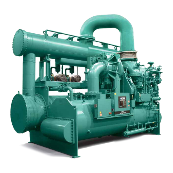
- Page 1 STEAM TURBINE CENTRIFUGAL LIQUID CHILLERS OPERATION & MAINTENANCE Supersedes: 160.67-O2 (415) Form 160.67-O2 (1020) MODEL YST CENTRIFUGAL LIQUID CHILLER DESIGN LEVEL F AND G Issue Date: October 9, 2020...
- Page 2 FORM 160.67-O2 ISSUE DATE: 10/9/2020 IMPORTANT! READ BEFORE PROCEEDING! GENERAL SAFETY GUIDELINES This equipment is a relatively complicated apparatus. which it is situated, as well as severe personal injury or During rigging, installation, operation, maintenance, death to themselves and people at the site. or service, individuals may be exposed to certain com- This document is intended for use by owner-authorized ponents or conditions including, but not limited to:...
- Page 3 MANUAL DESCRIPTION FORM NUMBER Unit Installation Manual 160.67-N2 OptiView Control Center - Operation Manual 160.67-O1 Wiring Diagram - Model YST (Style F) 160.67-PW6 Renewal Parts - Unit 160.67-RP1 Renewal Parts - Controls and Instrumentation 160.67-RP2 CONDITIONED BASED MAINTENANCE Traditional chiller maintenance is based upon assumed Planned Service Agreement that leverages real time and generalized conditions.
- Page 4 FORM 160.67-O2 ISSUE DATE: 10/9/2020 NOMENCLATURE The model number denotes the following characteristics of the unit. YST VF VD J4 - KD71750090 - 14 - 0.6 - 33192C - F S Chiller Model Special (Mandatory) Evaporator Code Design Level Condenser Code...
-
Page 5: Table Of Contents
FORM 160.67-O2 ISSUE DATE: 10/9/2020 TABLE OF CONTENTS SECTION 1 - DESCRIPTION OF SYSTEM AND FUNDAMENTALS OF OPERATION ........11 General System Description ........................... 11 Refrigeration System Operation ........................12 Capacity Controls ............................12 Steam and Condensate Flow ......................... 15 SECTION 2 - PRE-STARTUP AND SYSTEM OPERATING PROCEDURES .......... - Page 6 FORM 160.67-O2 ISSUE DATE: 10/9/2020 TABLE OF CONTENTS (CONT'D) Fixed Speed Chiller Unloading Sequence ...................... 39 PRV Control ............................39 Hot Gas Ratio Control ...........................39 HGV Temperature Controller .........................39 Fixed Speed Chiller Override Controllers ....................... 39 High and Low Refrigerant Pressure ...................... 39 Turbine Governor Position Power Limiting ....................
- Page 7 KD Turbine Auxiliary Oil Pump ......................55 Turbine Gland Seal System........................55 Types of Gland Leak-Off Systems ......................55 Gland Seal System: Standard YST Condensing Turbines ..............56 Gland Seal Wear ...........................56 Gland Seal Leak-Off Piping ........................56 Gland Leak-Off Condenser - Optional Supply by Special Quotation ............. 57 Vacuum Breaker Solenoid Valve ......................
- Page 8 FORM 160.67-O2 ISSUE DATE: 10/9/2020 TABLE OF CONTENTS (CONT'D) SECTION 5 – TROUBLESHOOTING ........................71 SECTION 6 - MAINTENANCE ..........................73 Renewal Parts ..............................73 Checking System For Leaks .......................... 73 Leak Testing During Operation ......................73 Evacuation And Dehydration Of Unit ......................73 Conducting R-22 Pressure Test........................
- Page 9 FIGURE 9 - Liquid Chiller Log Sheets ........................44 FIGURE 10 - System Components .........................49 FIGURE 11 - Schematic Drawing – (YST) Compressor Lubrication System ............51 FIGURE 12 - KD & KG Turbine Drawing ........................54 FIGURE 13 - Overspeed Protection Knob Assembly .....................60 FIGURE 14 - Oil Return System ..........................63...
- Page 10 FORM 160.67-O2 ISSUE DATE: 10/9/2020 THIS PAGE INTENTIONALLY LEFT BLANK. JOHNSON CONTROLS...
-
Page 11: Section 1 - Description Of System And Fundamentals Of Operation
ISSUE DATE: 10/9/2020 SECTION 1 - DESCRIPTION OF SYSTEM AND FUNDAMENTALS OF OPERATION GENERAL SYSTEM DESCRIPTION The YORK Model YST Chiller is a factory assembled • Power panel. steam turbine driven centrifugal compressor chiller. • Control center. It is commonly applied to large air conditioning sys-... -
Page 12: Refrigeration System Operation
The steam condenser package is furnished as an integral part of the YST system. See Steam and Condensate Flow, Figure 4 on page 16. The process water or other fluid that is chilled in the... - Page 13 FORM 160.67-O2 SECTION 1 - DESCRIPTION OF SYSTEM AND FUNDAMENTALS OF OPERATION ISSUE DATE: 10/9/2020 vanes completely closed. The combination of speed sure to maintain stable operation. The hot gas bypass control and PRV control will provide capacity reduc- valve is then modulated to admit condenser gas into the tion from 100% to 15% of design for normal air condi- evaporator and reduce the cooling effect as required.
-
Page 14: Figure 3 - Refrigerant Flow - Thru
FORM 160.67-O2 SECTION 1 - DESCRIPTION OF SYSTEM AND FUNDAMENTALS OF OPERATION ISSUE DATE: 10/9/2020 REFRIGERANT FLOW DIAGRAM LEGEND HIGH PRESSURE VAPOR COMPRESSOR HIGH PRESSURE LIQUID REFIGERANT LOW PRESSURE LIQUID REFIGERANT LOW PRESSURE VAPOR DISCHARGE HOT GAS BYPASS VALVE CONDENSER SUCTION ELIMINATOR SUB-COOLER... -
Page 15: Steam And Condensate Flow
FORM 160.67-O2 SECTION 1 - DESCRIPTION OF SYSTEM AND FUNDAMENTALS OF OPERATION ISSUE DATE: 10/9/2020 STEAM AND CONDENSATE FLOW of the condenser and is distributed longitudinally over (See Figure 4 on page 16) the tubes. When the steam contacts the relatively cool The primary function of a steam turbine is to convert tubes, it condenses. -
Page 16: Figure 4 - Steam And Condensate Flow
FORM 160.67-O2 SECTION 1 - DESCRIPTION OF SYSTEM AND FUNDAMENTALS OF OPERATION ISSUE DATE: 10/9/2020 STEAM AND CONDENSATE FLOW DIAGRAM GOVERNOR LD12547 FIGURE 4 - STEAM AND CONDENSATE FLOW JOHNSON CONTROLS... -
Page 17: Figure 5 - Steam Condenser Hotwell Level Switches
FORM 160.67-O2 SECTION 1 - DESCRIPTION OF SYSTEM AND FUNDAMENTALS OF OPERATION ISSUE DATE: 10/9/2020 STEAM CONDENSER HOTWELL LEVEL SWITCHES Level Transmitter High Level Switch Oper. Level Low Level Switch Magnetic Level Indicator LD09905 FIGURE 5 - STEAM CONDENSER HOTWELL LEVEL SWITCHES JOHNSON CONTROLS... - Page 18 FORM 160.67-O2 SECTION 1 - DESCRIPTION OF SYSTEM AND FUNDAMENTALS OF OPERATION ISSUE DATE: 10/9/2020 THIS PAGE INTENTIONALLY LEFT BLANK. JOHNSON CONTROLS...
-
Page 19: Section 2 - Pre-Startup And System Operating Procedures
FORM 160.67-O2 ISSUE DATE: 10/9/2020 SECTION 2 - PRE-STARTUP AND SYSTEM OPERATING PROCEDURES OVERVIEW Removal of foreign material from the The procedures that must be completed prior to each inlet steam piping is the responsibility of startup depend on the extent of time the chiller has the party installing the piping. -
Page 20: Inspect And Clean Steam Strainers
All loose parts (such as loose piping, etc.) should be cleaned and installed. Turbines packed for export, or The turbine on the standard YST chiller has a built-in protected for long storage periods may need to be com- type of strainer. This strainer should be inspected and pletely dismantled and cleaned to remove all protective cleaned periodically and checked for possible damage. -
Page 21: Check The Oil Level In The Turbine Bearing Reservoirs (Ring Oil Lubrication)
FORM 160.67-O2 SECTION 2 - PRE-STARTUP AND SYSTEM OPERATING PROCEDURES ISSUE DATE: 10/9/2020 Once the mylar has been removed and you are ready Ring Oil Lubrication to begin the oil flushing procedure, the following steps The oil level gauge on the side of the bearing should be followed: housing indicates the oil level. -
Page 22: Check The Oil Level In The Compressor Oil Reservoir
FORM 160.67-O2 SECTION 2 - PRE-STARTUP AND SYSTEM OPERATING PROCEDURES ISSUE DATE: 10/9/2020 ture falls to 4°F (2.2°C) or more below the target, the VERIFY THE COMPRESSOR OIL PUMP heater is turned on. It is turned off when the oil temper- OPERATION ature increases to 3°F (1.7°C) above the target value. -
Page 23: Verify The Compressor Pre-Rotation Vane Operation
The chiller cannot be started until the pre-rotation ual mode using the Pump Mode key on the CONDEN- vanes have been calibrated. On standard YST chill- SATE SCREEN, and immediately place the selected ers, the pre-rotation vanes are calibrated at the factory hotwell pump motor protector overload switch in the during functional testing. -
Page 24: Prepare The Steam Condenser Vacuum Pumps
FORM 160.67-O2 SECTION 2 - PRE-STARTUP AND SYSTEM OPERATING PROCEDURES ISSUE DATE: 10/9/2020 Test the operation of the standby pump the same as de- Ensure that the Vacuum Pump Motor Protector Over- scribed above. load switches are in the OFF position. If the chiller is equipped with an optional BUMP test the vacuum pump and standby pump (if standby pump, in the automatic mode, the... -
Page 25: Prepare The Steam Condenser Atmospheric Relief Valve
If both pumps fail, the chiller will be not Using the checklist in the YST Start-up checklist Form be allowed to start and will shutdown if 160.67-CL1, ensure that all setpoints are correct for the operating. -
Page 26: Sequence Of Operation
FORM 160.67-O2 SECTION 2 - PRE-STARTUP AND SYSTEM OPERATING PROCEDURES ISSUE DATE: 10/9/2020 air supply is available at the filter regulators on 9. Check the oil levels in the compressor and turbine the turbine governor valve and steam condenser. oil reservoirs. Check that 25 PSIG is available to the steam con- 10. -
Page 27: Slow Roll Time Calculation
353°F. OVERVIEW So we know that Ti = 353, Ns = 7 Standard YST chillers manufactured prior to Decem- SRT = 20 + 353-350 / 50 + 7 ber 2006 require the operator to manually open and... - Page 28 Start.” manufactured after December 2006 are supplied with enhanced governor con- YST chillers are factory configured with the Speed trols. The original turbine governor valve Control Mode set for Variable to automatically utilize and actuator were replaced with a ball...
-
Page 29: Figure 7 - Operation Sequence Timing Diagram (Manual Start)
FORM 160.67-O2 SECTION 2 - PRE-STARTUP AND SYSTEM OPERATING PROCEDURES ISSUE DATE: 10/9/2020 TIMING DIAGRAM – (MANUAL START) JOHNSON CONTROLS... -
Page 30: Figure 8 - Operation Sequence Timing Diagram (Automatic Start)
FORM 160.67-O2 SECTION 2 - PRE-STARTUP AND SYSTEM OPERATING PROCEDURES ISSUE DATE: 10/9/2020 TIMING DIAGRAM – (AUTOMATIC START) JOHNSON CONTROLS... -
Page 31: Startup Sequence Of Operation
FORM 160.67-O2 SECTION 2 - PRE-STARTUP AND SYSTEM OPERATING PROCEDURES ISSUE DATE: 10/9/2020 STARTUP SEQUENCE OF OPERATION 1. On the OptiView™ Control Center HOME Automatic Start: The main steam inlet block valve screen, press the STEAM SYSTEM key to go to and slow roll bypass valve air dump solenoids are the STEAM SYSTEM screen. - Page 32 FORM 160.67-O2 SECTION 2 - PRE-STARTUP AND SYSTEM OPERATING PROCEDURES ISSUE DATE: 10/9/2020 Automatic Start: The BEGIN SLOW ROLL key ring drain line prevents air from being drawn into does not appear and the start sequence proceeds the turbine when the turbine steam ring drops be- to paragraph 7.
- Page 33 FORM 160.67-O2 SECTION 2 - PRE-STARTUP AND SYSTEM OPERATING PROCEDURES ISSUE DATE: 10/9/2020 12. Perform the following while the turbine is slow (12 PSIA) and the vacuum pump is restarted. This rolling: energizes the sealing water solenoid valve. If flow is not established within 10 seconds after the a.
- Page 34 FORM 160.67-O2 SECTION 2 - PRE-STARTUP AND SYSTEM OPERATING PROCEDURES ISSUE DATE: 10/9/2020 17. When the chilled liquid flow switch contacts Whenever the turbine bearing supply oil pressure close, the speed setpoint is increased to the Fixed falls below the auxiliary oil pump control setting, Rated Speed of 3600 RPM at 200 RPM/second the auxiliary pump motor will be restarted.
-
Page 35: System Operating Procedure
FORM 160.67-O2 SECTION 2 - PRE-STARTUP AND SYSTEM OPERATING PROCEDURES ISSUE DATE: 10/9/2020 are increased to initiate the Capacity Ratchet For turbines with pressure feed lubrica- tion, the oil pressure should be observed Mode change to PRV before the HGV has actually frequently until the turbine has been closed fully and the mode change to Speed before operated for several days as failure of oil... -
Page 36: Shut Down Sequence Of Operation
FORM 160.67-O2 SECTION 2 - PRE-STARTUP AND SYSTEM OPERATING PROCEDURES ISSUE DATE: 10/9/2020 SHUT DOWN SEQUENCE OF OPERATION Normal (Controlled) Stop The chiller capacity will be reduced to perform a con- Automatic Start: When the Soft Shutdown is initi- trolled shutdown. This will slightly decrease the sud- ated, the Main Steam Inlet Valve control output den loss of steam load when the chiller trips, thus pos- is first decreased (ramped down at 5 %/second) - Page 37 FORM 160.67-O2 SECTION 2 - PRE-STARTUP AND SYSTEM OPERATING PROCEDURES ISSUE DATE: 10/9/2020 Automatic Start: The main steam inlet block valve closed if the cycling shutdown message "SYSTEM air dump solenoid is de-energized to close the CYCLING – CONTACTS OPEN" is displayed. valve immediately and its control signal is set to If the chilled liquid pump contacts are not 0%.
-
Page 38: Capacity Controls
Refer to the YST OptiView™ Control Logic Diagram sure differential. The Speed Control Mode is factory (Capacity Control 1, Capacity Control 2, and Capac-... -
Page 39: Fixed Speed Chiller Unloading Sequence
FORM 160.67-O2 SECTION 2 - PRE-STARTUP AND SYSTEM OPERATING PROCEDURES ISSUE DATE: 10/9/2020 FIXED SPEED CHILLER UNLOADING SEQUENCE PRV Control If the load decreases, the output of the Leaving Chilled trols at a leaving chilled liquid temperature set point Liquid Temperature Controller will decrease to close that is slightly below the main Leaving Chilled Liquid the vanes to the minimum position established by the Temperature Controller set point. -
Page 40: Turbine Governor Position Power Limiting
Turbine Horsepower Limiting being controlled. To achieve maximum efficiency at All new YST chillers are provided with a transmitter to part load conditions, the unloading sequence is speed monitor the turbine first stage pressure. This pressure reduction, vane closure, and hot gas valve opening. -
Page 41: Variable Speed Chiller Loading Sequence
FORM 160.67-O2 SECTION 2 - PRE-STARTUP AND SYSTEM OPERATING PROCEDURES ISSUE DATE: 10/9/2020 VARIABLE SPEED CHILLER LOADING SEQUENCE Hot Gas Mode the system pressure differential increases, the output of The chiller is started with the Leaving Chilled Liquid the Minimum Speed Calculation will increase and the Temperature Controller inactive and the hot gas con- speed set point signal is immediately set to the higher trol signal at 100%. -
Page 42: Prv Mode
FORM 160.67-O2 SECTION 2 - PRE-STARTUP AND SYSTEM OPERATING PROCEDURES ISSUE DATE: 10/9/2020 PRV Mode When the Leaving Chilled Liquid Temperature Con- the HGV. As the HGV is opened, the system pressure troller output is equal to the Minimum Speed Calcu- differential will decrease resulting in lower outputs lation output signal, the Leaving Chilled Liquid Tem- from the Minimum Speed Calculation and Minimum... -
Page 43: Turbine Horsepower Limiting
Turbine Horsepower Limiting printer and programming the DATA LOGGER func- All new YST chillers are provided with a transmitter to tion. See Form 160.67-O1, Section 3 - Printers for ad- monitor the turbine first stage pressure. This pressure ditional information. -
Page 44: Operating Inspections
FORM 160.67-O2 SECTION 2 - PRE-STARTUP AND SYSTEM OPERATING PROCEDURES ISSUE DATE: 10/9/2020 OPERATING INSPECTIONS By following a regular inspection using the display 6. Check the compressor discharge temperature on readings of the Microcomputer Control Center, and the SYSTEM Screen. During normal operation maintenance procedure, the operator will avoid serious discharge temperature should not exceed 220°F operating difficulty. -
Page 45: Ring Oil Lubrication
FORM 160.67-O2 SECTION 2 - PRE-STARTUP AND SYSTEM OPERATING PROCEDURES ISSUE DATE: 10/9/2020 Ring Oil Lubrication The oil level gauge on the side of the bearing housing 14. Observe supply pressure from pressure reducing indicates the oil level. A mark inscribed on the low- valve for air in bearing seal air purge piping to er-half bearing housing indicates the proper oil level. -
Page 46: Semi-Annually (Or More Often As Required)
FORM 160.67-O2 SECTION 2 - PRE-STARTUP AND SYSTEM OPERATING PROCEDURES ISSUE DATE: 10/9/2020 2. Clean all linkage systems and inspect for wear. On 4. Perform refrigerant analysis. the turbine, clean and oil or grease all the moving 5. Remove and clean the Steam Strainer on the Tur- parts (fulcrum points). -
Page 47: System Shutdown
ISSUE DATE: 10/9/2020 SYSTEM SHUTDOWN are subjected to moisture and contaminants that will The following are methods for stopping the YST sys- shorten the life expectancy of the machine. The tur- tem; bine must be protected from corrosion internally with a •... -
Page 48: Turbine Lubrication System
FORM 160.67-O2 SECTION 2 - PRE-STARTUP AND SYSTEM OPERATING PROCEDURES ISSUE DATE: 10/9/2020 • Electric magnetic heaters can be applied to the Other Recommendations casing to help keep the turbine dry. If the turbine is to be idle for a period longer than eight months, Johnson Controls Service office should be •... -
Page 49: Section 3 - System Components Description
FORM 160.67-O2 ISSUE DATE: 10/9/2020 SECTION 3 - SYSTEM COMPONENTS DESCRIPTION STEAM TURBINE GOVERNOR VALVE STEAM CONDENSER PACKAGE VACUUM BREAKER SOLENOID VALVE TURBINE OIL COOLING WATER INLET VALVE CONDENSER COMPRESSOR COMPRESSOR OIL TURBINE COOLING WATER INLET VALVE CONTROL CENTER POWER HOT GAS BYPASS PANEL VALVE... -
Page 50: General
ISSUE DATE: 10/9/2020 GENERAL ometry Diffuser Screen as “Stall Detector Voltage” The YORK Model YST Centrifugal Liquid Chiller and is input to the Microboard where it is compared to Unit is completely factory-packaged including; the the Low Limit and High Limit setpoint thresholds to... -
Page 51: Figure 11 - Schematic Drawing - (Yst) Compressor Lubrication System
OIL FILTER LIQUID LEVEL GAUGE 3-PHASE OIL HEATER OIL TEMPERATURE CONTROL VALVE ANGLE DRAIN SUBMERSIBLE VALVE OIL PUMP WITH 3-PHASE MOTOR LIQUID COOLED OIL COOLER COOLING LIQUID LD09580 FIGURE 11 - SCHEMATIC DRAWING – (YST) COMPRESSOR LUBRICATION SYSTEM JOHNSON CONTROLS... -
Page 52: Compressor Oil Pump
FORM 160.67-O2 SECTION 3 - SYSTEM COMPONENTS DESCRIPTION ISSUE DATE: 10/9/2020 COMPRESSOR OIL PUMP The oil heater is automatically controlled by the control panel at all times during The compressor oil pump operation is automatically shutdown, slow roll and ramp up to rated controlled from the panel. -
Page 53: Steam Turbine Inlet Valves
Two types of lubrication are supplied on steam turbines furnished on YST systems. The smaller turbine design, KG, has an integral lube system and is used for designs For speed and overspeed control the turbine has two up to 1700 HP. -
Page 54: Figure 12 - Kd & Kg Turbine Drawing
FORM 160.67-O2 SECTION 3 - SYSTEM COMPONENTS DESCRIPTION ISSUE DATE: 10/9/2020 KD TURBINE (LARGE) FIRST STAGE SENTINEL WARNING VALVE PRESSURE TRANSMITTER TURBINE TRIP VALVE LIMIT SWITCH VACUUM BREAKER SOLENOID TURBINE NOZZLE VALVE AIR DUMP SOLENOID VALVE TURBINE AUXILIARY OIL PUMP MOTOR STEAM RING DRAIN SOLENOID SHAFT OIL PUMP... -
Page 55: Kg Steam Turbine With Ring Oil Lubrication
The inlet condense in the oil reservoir. steam pressure for standard YST turbines can be from 90 to 200 psig depending on the design for the particu- lar job. The outlet steam pressure is below atmospher- The bearing housings are continuously purged during ic, typically in the neighborhood of 1.5 PSIA. -
Page 56: Gland Seal System: Standard Yst Condensing Turbines
SECTION 3 - SYSTEM COMPONENTS DESCRIPTION ISSUE DATE: 10/9/2020 • Steam finds its way to the bearing housings, con- Gland Seal System: Standard YST denses there and contaminates the oil. Condensing Turbines Turbines are equipped with a gland seal system similar •... -
Page 57: Gland Leak-Off Condenser - Optional Supply By Special Quotation
The The condenser is piped to the outer leak-off connec- valve is set to open at 5 psig on the standard YST Con- tions of the glands. It creates a slight vacuum on the densing Turbine. -
Page 58: Pressure Powered Condensate Drain Pump
When either option is supplied, it is shipped loose for open allowing condensate to re-enter through the inlet installation at the job site. check valve and the cycle is repeated. Refer to YORK standard flow diagram for typical pressure pump pip- On non-condensing turbines with side-discharge tur- ing installation. -
Page 59: Turbine Governor And Overspeed Controls
FORM 160.67-O2 SECTION 3 - SYSTEM COMPONENTS DESCRIPTION ISSUE DATE: 10/9/2020 TURBINE GOVERNOR AND OVERSPEED HEAT EXCHANGERS CONTROLS Evaporator and refrigerant condenser shells are fabri- Protection from turbine overspeed is an important con- cated from rolled carbon steel plates with fusion weld- sideration and the following are four methods of pro- ed seams. -
Page 60: Refrigerant Flow Control
FORM 160.67-O2 SECTION 3 - SYSTEM COMPONENTS DESCRIPTION ISSUE DATE: 10/9/2020 OPTIONAL SERVICE ISOLATION VALVES If the chiller is equipped with optional service isolation valves on the compressor discharge and main liquid line to the evaporator, these valves must remain open during operation. -
Page 61: Power Panel
FORM 160.67-O2 SECTION 3 - SYSTEM COMPONENTS DESCRIPTION ISSUE DATE: 10/9/2020 inlet and hotwell pump discharge piping. Temperature POWER PANEL gauges are located at the steam inlet, cooling water in- All motor contactors and circuit protectors, the com- let and outlet, and the hotwell. pressor oil pump variable speed drive and the control power transformer are contained in an enclosure in- Piping is fitted with unions at suitable break-points. -
Page 62: Hotwell (Condensate) Pump
FORM 160.67-O2 SECTION 3 - SYSTEM COMPONENTS DESCRIPTION ISSUE DATE: 10/9/2020 Hotwell (Condensate) Pump Level Control The hotwell pump(s) is a 5 HP, 3600 RPM motor driven The condensate level in the hotwell is controlled auto- direct connected pump with a maximum suction pres- matically during operation by a level control system. -
Page 63: Section 4 - Operational Maintenance
FORM 160.67-O2 ISSUE DATE: 10/9/2020 SECTION 4 - OPERATIONAL MAINTENANCE COMPRESSOR OIL RETURN SYSTEM The oil return system continuously maintains the prop- 2. Remove the dehydrator. er oil level in the compressor oil sump. 3. Assemble the new filter-drier. High pressure condenser gas flows continuously 4. -
Page 64: The Compressor Oil Charge
(A) located on the remote oil reservoir THE COMPRESSOR OIL CHARGE cover plate. Do not tighten the connection at the The nominal oil charge for all YST compressors is 20 charging valve until after the air is forced out gallon, type “York K”. -
Page 65: Compressor Oil Filter
The oil filter(s) are a replaceable 3 mi- port fitting, located on the top of the filter housing. cron cartridge type oil filter. Use only YORK approved Connect a refrigeration pressure hose to the pres- oil filter elements. -
Page 66: Dual Oil Filter Replacement
FORM 160.67-O2 SECTION 4 - OPERATIONAL MAINTENANCE ISSUE DATE: 10/9/2020 of the bearing housing indicates the oil level. A mark Dual Oil Filter Replacement inscribed on the lower-half bearing housing indicates The dual oil filter option allows one oil filter to be iso- the proper oil level. -
Page 67: Pressure Lubrication
If there are any doubts about the particular oil for tur- and cover the fill connection when finished. Make bine use, consult the YORK Service Department. sure the gland system works properly. For details, see Turbine Gland Seal System on page 55 for details. -
Page 68: Lube Oil Flushing
Reseal the upper bearing housing cover and replace the bolting. All YST Chillers shipped Form 1 are charged with the correct amount of refrigerant. Under some operating The following steps should be followed: conditions the chiller may appear to be overcharged or undercharged with refrigerant. -
Page 69: Refrigerant Charging
Should it become necessary to add refrigerant charge to All threaded pressure connections used on the YORK a YORK YST Chiller; add charge until the evaporator YST Chillers are SAE straight thread, O-ring face seal approach and refrigerant gas discharge superheat are type fittings or Primore Rotalock fittings. - Page 70 FORM 160.67-O2 SECTION 4 - OPERATIONAL MAINTENANCE ISSUE DATE: 10/9/2020 THIS PAGE INTENTIONALLY LEFT BLANK. JOHNSON CONTROLS...
-
Page 71: Section 5 - Troubleshooting
FORM 160.67-O2 ISSUE DATE: 10/9/2020 SECTION 5 – TROUBLESHOOTING TABLE 3 - OPERATION ANALYSIS CHART RESULTS POSSIBLE CAUSE REMEDY 1. Symptom: Abnormally High Discharge Pressure Temperature difference between condensing temperature and water off Air in Condenser condenser higher than normal Clean condenser tubes. - Page 72 FORM 160.67-O2 SECTION 5 – TROUBLESHOOTING ISSUE DATE: 10/9/2020 TABLE 3 - OPERATION ANALYSIS CHART (CONT'D) Replace low or high oil pressure Unusually high oil pressure is displayed High oil pressure. Transducer/ transducer or turbine supply oil when the oil pump is running. Transmitter defective.
-
Page 73: Section 6 - Maintenance
FORM 160.67-O2 ISSUE DATE: 10/9/2020 SECTION 6 - MAINTENANCE RENEWAL PARTS EVACUATION AND DEHYDRATION OF UNIT For any required Renewal Parts, refer to YORK Renew- al Parts Unit Components Manual 160.67-RP1. CHECKING SYSTEM FOR LEAKS COMPRESSOR OIL COOLER Leak Testing During Operation... -
Page 74: Conducting R-22 Pressure Test
FORM 160.67-O2 SECTION 6 - MAINTENANCE ISSUE DATE: 10/9/2020 2. Open wide all system valves. Be sure all valves to CONDUCTING R-22 PRESSURE TEST the atmosphere are closed. With the R-134a charge removed and all known leaks repaired, the system should be charged with a small 3. -
Page 75: Operation
FORM 160.67-O2 SECTION 6 - MAINTENANCE ISSUE DATE: 10/9/2020 taken place the pressure and temperature will continue to drop until eventually a temperature of 35°F (1.6°C) or a pressure of 5 mm Hg. is reached. When this point is reached, practically all of the air has been evacuated from the system, but there is still a small amount of moisture left. -
Page 76: Checking The Refrigerant Charge During Unit Shutdown
FORM 160.67-O2 SECTION 6 - MAINTENANCE ISSUE DATE: 10/9/2020 As a preventive measure against scale and corrosion CHECKING THE REFRIGERANT CHARGE and to prolong the life of evaporator and condenser DURING UNIT SHUTDOWN tubes, a chemical analysis of the water should be made The refrigerant charge is specified for each chiller preferably before the system is installed. -
Page 77: Tube Cleaning Procedures
Pressurize the dry system with 50 to and condensers. If acid cleaning is required, YORK 100 PSIG (345 to 690 kPa) of nitrogen. Repeat recommends the use of this type of organization. The... -
Page 78: Compressor Maintenance
FORM 160.67-O2 SECTION 6 - MAINTENANCE ISSUE DATE: 10/9/2020 4. After the tubes have been corked for 12 to 24 STEAM CONDENSER CONDENSATE PUMP hours, it is recommended that two men working MAINTENANCE at both ends of the evaporator carefully test each While the pump is running, re-grease the pump bear- tube –... - Page 79 FORM 160.67-O2 SECTION 6 - MAINTENANCE ISSUE DATE: 10/9/2020 These joints have been kept in contact by the bolts After the parts are free, a chain hoist can be used to while under prolonged exposure to heat and moisture. remove cover and rotor. The lower diaphragm portion Even though joint compounds have been used at the cannot rise and the upper portion is fastened to it.
-
Page 80: Check The Casing Interior For Foreign Material Before Closing
FORM 160.67-O2 SECTION 6 - MAINTENANCE ISSUE DATE: 10/9/2020 CHECK THE CASING INTERIOR FOR FOREIGN MATERIAL BEFORE CLOSING. The casing cover should be carefully lowered. If it ap- The following torques are to be applied to socket pears to “hang up”, use a slight rocking motion to assist head and hex head capscrews, bolts, and nuts of proper mating of parts. -
Page 81: Section 7 - Preventive Maintenance
YORK office for their refrigerant may have leaked from the chiller. further investigation and recommendations. - Page 82 FORM 160.67-O2 SECTION 7 - PREVENTIVE MAINTENANCE ISSUE DATE: 10/9/2020 JOHNSON CONTROLS...
- Page 83 FORM 160.67-O2 SECTION 7 - PREVENTIVE MAINTENANCE ISSUE DATE: 10/9/2020 JOHNSON CONTROLS...
- Page 84 FORM 160.67-O2 SECTION 7 - PREVENTIVE MAINTENANCE ISSUE DATE: 10/9/2020 JOHNSON CONTROLS...
- Page 85 FORM 160.67-O2 SECTION 7 - PREVENTIVE MAINTENANCE ISSUE DATE: 10/9/2020 JOHNSON CONTROLS...
-
Page 86: Steam Purity/Turbine Deposits
Their maintenance will ensure protection If possible the upper half casing should be removed, of the turbine. under supervision of a YORK Service Representative for better inspection. Warranty may be void in the event opera- tional failure is attributed to inadequate Pitting of the blades and nozzles is evidence of a cor- boiler feed water treatment. -
Page 87: Table 7 - Recommended Limits For Boiler Water (Based On Drum Water Analyses)
FORM 160.67-O2 SECTION 7 - PREVENTIVE MAINTENANCE ISSUE DATE: 10/9/2020 TABLE 7 - RECOMMENDED LIMITS FOR BOILER WATER (BASED ON DRUM WATER ANALYSES). PRESSURE AT TOTAL OUTLET OF STEAM SILICA PHOSPHATE SULFITE HARDNESS CHLORIDES SOLIDS ALKALINITY GENERATING UNIT, PSIG 0-150 2,000 151-450 1,500... -
Page 88: Temperature
FORM 160.67-O2 SECTION 7 - PREVENTIVE MAINTENANCE ISSUE DATE: 10/9/2020 The following factors can be used to convert from English to the most common SI Metric values. TABLE 8 - SI METRIC CONVERSION MEASUREMENT MULTIPLY ENGLISH UNIT BY FACTOR TO OBTAIN METRIC UNIT Capacity Tons Refrigerant Effect (ton) 3.516... -
Page 89: Notes
FORM 160.67-O2 NOTES ISSUE DATE: 10/9/2020 NOTES JOHNSON CONTROLS... - Page 90 5000 Renaissance Drive, New Freedom, Pennsylvania USA 17349 1-800-524-1330 Subject to change without notice. Printed in USA Copyright © by Johnson Controls 2020 www.johnsoncontrols.com ALL RIGHTS RESERVED Form 160.67-O2 (1020) Issue Date: October 9, 2020 Supersedes: 160.67-O2 (415)