Table of Contents
Advertisement
BA 009D/06/en/04.99
No. 50063718
CV 5.0
Valid as of software version
V 3.01.XX (amplifier)
V 2.04.XX (communication)
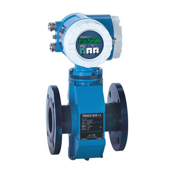
Promag 33
Electromagnetic
Flow Measuring System
Operating Manual
+
Endress
Nothing beats know-how
Hauser
Advertisement
Table of Contents

Related Manuals for Endress+Hauser PROMAG 33


Summary of Contents for Endress+Hauser PROMAG 33
- Page 1 BA 009D/06/en/04.99 promag 33 No. 50063718 CV 5.0 Electromagnetic Valid as of software version V 3.01.XX (amplifier) Flow Measuring System V 2.04.XX (communication) Operating Manual Endress Hauser Nothing beats know-how...
-
Page 2: Table Of Contents
Promag 33 Brief Operating Instructions With the following instructions, you may configure your measuring instrument quickly and easily: → see page 5 → see page 47 ff. Safety instructions Engineering units ↓ ↓ Configuration of outputs Mounting and electrical connection •... -
Page 3: Table Of Contents
Mounting and Installation ..Dimensions ..99 Transport instructions (DN ≥ 350/14") . . Dimensions Promag 33 A ..Mounting location .. - Page 4 Promag 33 Registered Trademarks ® ® ® KALREZ , VITON and TEFLON Registered trademarks of E.I. Du Pont de Nemours & Co., Wilmington, USA ® ® TRI-CLAMP , HASTELLOY Registered trademarks of Ladish & Co., Inc., Kenosha, USA Endress+Hauser...
-
Page 5: Correct Usage
1 Safety Instructions 1.1 Correct usage • The Promag 33 measuring system is only to be used for measuring the flow of conductive fluids. Most liquids can be measured provided they have a minimum conductivity of ≥ 5 µS/cm, e.g. -
Page 6: Personnel For Installation, Start-Up And Operation
Warning! longer present. 1.4 Repairs and dangerous substances The following procedures must be carried out before a Promag 33 is sent to Endress+Hauser for repair: • A note must always be enclosed with the instrument, containing a description of the fault, the application, and the chemical and physical properties of the product being measured. -
Page 7: 2 Instrument Identification
Promag 33 2 Instrument Identification 2 Instrument Identification An overview of the complete Promag 33 measuring system is shown below. The technical specifications are stamped on the nameplate and contain the following information: Promag 33 transmitter Promag A Promag H... - Page 8 2 Instrument Identification Promag 33 Promag A, H and F sensors Promag F (15...2000) (DN 15...300) Order code / Serial number Definition code: see specifications on order confirmation ENDRESS+HAUSER Calibration factor / Zero point PROMAG F 0.5328 / –5 Order Code:...
-
Page 9: Transport Instructions (Dn ≥ 350/14")
Promag 33 3 Mounting and Installation 3 Mounting and Installation Warning! • The instructions given in this section are to be observed at all times in order to ensure safe and reliable operation of the measuring system. Warning! • For explosion protected instruments the mounting regulations and the technical data may differ from those stated here. -
Page 10: Mounting Location
3 Mounting and Installation Promag 33 3.2 Mounting location Correct measurement is only possible when the pipe is full. The following locations should therefore be avoided: • No installation at the highest point (air accumulation). • No installation immediately before an open pipe outlet in a downward line. - Page 11 Promag 33 3 Mounting and Installation Installation of pumps Do not mount the sensors on the suction side of pumps. This prevents low pressure and therefore possible damage to the lining of the measuring tube. Information on the resistance to vacuum of the flowmeter lining can be found on page 115.
-
Page 12: Mounting Position
3 Mounting and Installation Promag 33 3.3 Mounting position Vertical mounting: This is the recommended position with the flow upwards. Entrained solid particles sink and fatty components in the stationary fluid rise away from the measuring electrodes. This is the... -
Page 13: Nominal Diameter And Flow Rate
Promag 33 3 Mounting and Installation 3.4 Nominal diameter and flow rate The diameter of the pipe usually governs the nominal diameter of the sensor. The optimum flow velocity range is between v = 2...3 m/s. Furthermore, the flow velocity (v) has to be matched to the physical properties of the fluid: •... -
Page 14: Adapters
3 Mounting and Installation Promag 33 3.5 Adapters The sensor can also be mounted in a pipe with a larger nominal diameter when suitable adapters (reducers and expanders) to DIN 28545 are fitted. The resultant increase in the rate of flow increases the accuracy of measurement with slowly moving fluids. -
Page 15: Mounting Promag A Sensor
Promag 33 3 Mounting and Installation 3.6 Mounting Promag A sensor Various process connections are available for the Promag A sensor. The process connections (adapters) are mounted in two ways: A. Coupling nut on a 1" threaded stub (mounting set) •... -
Page 16: Mounting Promag H Sensor
Caution! The electronics may be destroyed! Take care that the welding ground is not via the Promag 33 H sensor or housing. Caution! 1. Fasten the Promag H sensor with some spot welds into the pipe. 2. Loosen the screws at the process-connector flange and remove the sensor from the pipe;... -
Page 17: Mounting Promag F Sensor
Ensure that the lining on the flange is not damaged or removed. These disks must remain in position during storage. Caution! Fig. 15 Mounting Promag 33 F Seals • If the measuring tube liner is made of soft rubber or Teflon (PTFE), a flange seal is not required. - Page 18 3 Mounting and Installation Promag 33 Screw tightening torques (Promag F) The tightening torques listed apply to greased threads. Screws tightened up too tightly deform the sealing surface. Special attention should be paid to soft rubber linings. Note! The tightening torques given here apply only to those pipes which are not subject Note! to mechanical stress.
-
Page 19: Turning The Transmitter Housing And Local Display
Promag 33 3 Mounting and Installation 3.9 Turning the transmitter housing and local display The transmitter housing and local display can be rotated in steps of 90°. This enables the unit to be adapted to different mounting positions in the piping and so simplifying reading and operation. -
Page 20: Mounting The Transmitter (Remote Version)
3 Mounting and Installation Promag 33 3.10 Mounting the transmitter (remote version) The transmitter has to be mounted remote from the sensor when: • access is difficult, • space is restricted, • extreme process and ambient temperatures prevail (for temperature ranges see page 110), •... -
Page 21: Degree Of Protection
Promag 33 4 Electrical Connection 4 Electrical Connection Warning! • When connecting Ex-approved instruments, please observe all instructions and wiring diagrams given in the Ex supplement to this Operating Manual. Your E+H representative will be pleased to provide you with more information. -
Page 22: Connecting The Transmitter
4 Electrical Connection Promag 33 4.2 Connecting the transmitter Warning! • Risk of electric shock! Switch off the power supply before opening the instrument. Do not install or wire the unit while connected to the power supply. Failure to comply may also result in damage of electronic components. - Page 23 < 700 Ω (with HART: R ≥ 250 Ω) 0/4...20 mA, R Ground connection (screening of signal cable) The input and outputs are galvanically isolated from the power supply and from each other. Fig. 22 Terminal compartment Promag 33 (HART) Endress+Hauser...
- Page 24 * Only one version is possible for each, depending on the setting selected in the function “SYSTEM CONFIG.” (see page 71). The input and outputs are galvanically isolated from the power supply and from each other. Fig. 23 Terminal compartment Promag 33 (RS 485) Endress+Hauser...
-
Page 25: Connecting The Cable Of The Remote Version
Promag 33 4 Electrical Connection 4.3 Connecting the cable of the remote version Warning! Danger from electric shock! Switch off the power supply before opening the instrument. Warning! 1. Loosen the safety grip and remove the cover of the transmitter housing . - Page 26 4 Electrical Connection Promag 33 Wiring diagrams for the remote version (FS/FL) Remote version “FS” Promag 33 A Promag 33 H / F Transmitter Transmitter Coils Coils 4 37 23 22 Coils Coils Sensor Sensor Remote version “FL” Promag 33 A...
-
Page 27: Cable Specifications
* braided copper screen (coil cable ∅ ~ 7 mm; signal cable ∅ ~ 9 mm) Operation in areas with severe electrical interference The Promag 33 measuring system fulfils all general safety requirements according to EN 61010 and electromagnetic compatibility (EMC) according to EN 50081 Part 1 and 2 / EN 50082 Part 1 and 2 when installed in accordance with the NAMUR recommendations. -
Page 28: Potential Equalisation
Promag 33 transmitter housing to the potential equalisation line in order to pre- vent corrosion. The connection with the remote-mounted version is made at the ground terminal of the connection housing. - Page 29 Grounding in an area with severe interference The fluid may be grounded. In order to make the most of the electromagnetic compatibility (EMC) of the Promag 33, it is advisable to provide two flange-to- flange links and to connect them jointly with the transmitter housing to ground potential.
-
Page 30: Connecting E+H Rackbus And Rackbus Rs 485
Promag 33 4.6 Connecting E+H Rackbus and Rackbus RS 485 Promag 33 can be linked to other E+H measuring instruments using an E+H-Rackbus and a Rackbus RS 485 and connected to higher process-control systems such as MODBUS, PROFIBUS, ControlNet etc., with the help of a corresponding gateway (see Fig. - Page 31 Promag 33 4 Electrical Connection Direct connection to a PC Personal computer with “Commuwin II” program and with a ZA 672-DDE server Commubox FXA 192 Rackbus RS 485 Fig. 31 Direct PC connection to Rackbus RS 485 via Commubox FXA 192...
- Page 32 4 Electrical Connection Promag 33 Connecting a Promag 33 to a RS 485 Rackbus Warning! • Danger from electrical shock! Switch off power supply before opening the transmitter housing. • If instruments with Ex approvals are used, please observe all instructions and regulations of the Ex Warning! supplementary documentation.
-
Page 33: Promag
Promag 33 4 Electrical Connection 4.7 Connecting HART Communicator The following connection versions are available to the user: • Direct connection to the Promag transmitter via Terminals 26/27 • Connection via the analogue 4...20 mA cable of the current output Note! The measuring loop must have a minimum resistance of 250 Ω. -
Page 34: Commissioning
4 Electrical Connection Promag 33 4.9 Commissioning Before switching on the measuring system, the following checks should be carried out again: • Check the electrical connections and terminal assignments. • Compare the data on the nameplate with the local mains voltage and frequency. -
Page 35: Display And Operating Elements
5 Display and Operation 5 Display and Operation 5.1 Display and operating elements With the Promag 33 display, all important parameters can be read off or configured using the E+H operating matrix. LC Display • Illuminated, double-spaced with 16 characters. -
Page 36: Operation (Operating Matrix)
5 Display and Operation Promag 33 5.2 Operation (operating matrix) Access to the operating matrix (from the HOME position) Select function group (> GROUP SELECT. <) Select function (enter parameters or numeric values with and store with Overview of all functions and parameters → see page 117 Operating example →... - Page 37 Promag 33 5 Display and Operation Endress+Hauser...
- Page 38 Promag 33 Further information on programming For the Promag 33 measuring system, there is a wide choice of functions and parame- ters which the user can set individually and adapt to the condition of his process. The individual functions are allocated to various function groups (see page 37).
-
Page 39: Operating Example
Promag 33 5 Display and Operation 5.3 Operating example To change the time constant set in the factory at “1.0 s” to “20 s”, then proceed as follows: HOME position (Display during normal measuring operation) 2 9 0 . 8 2 m / h 2 . -
Page 40: Operation With The Hart Protocol
“Commubox FXA 191” HART modem. Operating using the “HART Communicator DXR 275” Promag 33 functions are selected with the HART communicator over a number of menu levels as well as with the aid of a special E+H operating matrix (see Fig. 40). - Page 41 Promag 33 5 Display and Operation Fig. 40 HART operating matrix Promag 33 Endress+Hauser...
-
Page 42: Operating Rackbus Rs 485
5 Display and Operation Promag 33 Operating using the “Commuwin II” program Commuwin II is a universal program for remote operation of field and control-room devices. Use of the Commuwin II operating program is possible independent of the type of instrument or Communication (HART, PROFIBUS, Rackbus RS 485, etc.) chosen. - Page 43 Promag 33 5 Display and Operation Endress+Hauser...
- Page 44 5 Display and Operation Promag 33 Operating Matrix for Rackbus RS 485 FLOWRATE TOTALIZED VOL. FLOW RATE UNITS VOLUME UNITS MEASURED VALUE 0: dm3/s 12: gal/h 0: dm3 1: dm3/min 13: gal/day 1: m3 2: dm3/h 14: gpm 2: l...
- Page 45 Promag 33 5 Display and Operation Operating Matrix for Rackbus RS 485 GALLON / BARREL PIPE SIZE UNIT 0: 31 gal 0: mm 1: 31.5 gal 1: inch 2: 42 gal 3: 55 gal 4: 36 ImpGal 5: 42 ImpGal...
- Page 46 5 Display and Operation Promag 33 Endress+Hauser...
- Page 47 6 Description of Functions This section is an in-depth description of the individual functions and specifications of Promag 33. Factory settings are indicated in bold italics . On request, Promag 33 measuring instruments are also available with customised parameterisation. In such cases, values or settings may differ from the factory settings shown here.
- Page 48 6 Description of Functions Promag 33 Function group SYSTEM UNITS In the USA and UK, the ratio of barrels (bbl) to gallons (gal) is defined GALLONS / according to the fluid used and the specific industry. Therefore the BARREL following definitions have to be selected: •...
- Page 49 Promag 33 6 Description of Functions Function group CURRENT OUTPUT This function group is not available when the setting “RS 485 / FREQUENCY” or “AUX. INPUT / FREQ.” is shown in the function “SYSTEM CONFIG.” for the communication module RS 485 (see page 71).
- Page 50 – Full scale value 1 active → Relay 1 or 2 energised (live) – Full scale value 2 active → Relay 1 or 2 de-energised (dead) • If the Promag 33 measuring electronics are fitted with a communication module “RS 485”, then the full scale values 1/2 can also be activated using the auxiliary input (see page 69).
- Page 51 Promag 33 6 Description of Functions Function group CURRENT OUTPUT Description of function → see function “FULL SCALE 1” (page 49) FULL SCALE 2 Note! This function is only available if the “DUAL RANGE MODE” function is activated (see page 50).
- Page 52 6 Description of Functions Promag 33 Function group CURRENT OUTPUT In this function, the output current can be simulated to correspond to 0%, 50% SIMULATION or 100% of the set current range. The ‘error values’ 2 mA (for 4...20 mA) and CURRENT 25 mA (maximum possible value) or 22 mA for NAMUR can also be simulated.
- Page 53 Promag 33 6 Description of Functions Function group PULSE / FREQ. OUTPUT This function group is not available when the setting “RS 485 / CURRENT” or “AUX. INPUT / CURRENT” is shown in the function “SYSTEM CONFIG.” for the communication module RS 485 (see page 71).
- Page 54 6 Description of Functions Promag 33 Function group PULSE / FREQ. OUTPUT Enter the full scale frequency (2...10000 Hz) for the max. flow rate required. FULL SCALE The corresponding full scale value is defined in the function “FULL SCALE FREQ.
- Page 55 Promag 33 6 Description of Functions Function group PULSE / FREQ. OUTPUT Entry of the required full scale value for the flow rate. FULL SCALE Scaling always applies to both directions of flow (bidirectional), but with the FLOW unidirectional mode, no signal is given for a negative flow.
- Page 56 6 Description of Functions Promag 33 Function group PULSE / FREQ. OUTPUT With this function the pulse/frequency output can be configured as required, OUTPUT SIGNAL for example for an external counter. ACTIVE → Internal power supply used (+24 V) PASSIVE → External power supply required...
- Page 57 Promag 33 6 Description of Functions Function group PULSE / FREQ. OUTPUT In cases of an instrument error it is advisable for safety reasons that the FAILSAFE MODE pulse/frequency output assumes a previously defined status which can be set in this function.
- Page 58 6 Description of Functions Promag 33 Function group RELAYS Selection of the relay function. The setting “FAILURE” can only be assigned to RELAY 1 relay 1, not to relay 2!. FUNCTION Notes! • Note page 60 and 61 for the switching response of relay 1.
- Page 59 Promag 33 6 Description of Functions Function group RELAYS If you have configured Relay 1 for “FLOW DIRECTION” or “LIMIT FLOWRATE”, RELAY 1 you may determine the necessary switching points in these functions. ON-VALUE Relay 1 → “FLOW DIRECTION” RELAY 1...
- Page 60 6 Description of Functions Promag 33 Functions State Relay Relay contact * Relay 1 NC contact * NO contact * FAILURE System OK energised ENDRESS+HAUSER PROMAG 33 Failure ENDRESS+HAUSER PROMAG 33 (system error) de-energised ERROR + EPD System OK ENDRESS+HAUSER...
- Page 61 Promag 33 6 Description of Functions Common State Relay Relay contact * Functions NC contact * NO contact * Relay 1 and 2 Full scale value 1 < 2 Full scale value 1 > 2 DUAL RANGE MODE 22 / 24...
- Page 62 6 Description of Functions Promag 33 Function group RELAYS Selection of the relay function (Relay 2). RELAY 2 FUNCTION Notes! • Note page 60 and 61 for the switching response of relay 2. • As standard the normally closed contact of relay 2 is brought out. However,...
- Page 63 BATCHING Introduction The “BATCHING” function group together with the preset totalizer enables simple batching cycles to be controlled. The Promag 33 transmitter has two relays which can be used for controlling single or two-stage batching cycles: Single-stage batching cycle Batch quantity...
- Page 64 6 Description of Functions Promag 33 Function group BATCHING In this function, the batching mode can be activated or switched off. BATCH VARIABLE Note! If the batching mode is activated, the “BATCHING” Function group is first shown on the display when entering the operating matrix. The “BATCH VARIABLE”...
- Page 65 Promag 33 6 Description of Functions Function group BATCHING In this function a positive or negative compensation quantity is defined. This COMPENS. quantity compensates for a consistent error in batching amounts due to plant QUANTITY operation. This can be caused, e.g. due to after running of a pump or the closing time of a valve.
- Page 66 6 Description of Functions Promag 33 Function group DISPLAY Display of the totalised flow quantity from when measurement began. TOTAL VOLUME This value is either positive or negative depending on the direction of flow. Notes! • If the count has more figures than can be displayed, e.g. with overflow, then the symbol “>”...
-
Page 67: Assign Line
• The overflow as well as the totalizer value in the HOME position are reset to zero. • If the Promag 33 measuring electronics are fitted with a communications Note! module “RS 485”, then the totalizer reset can also be carried out with the auxiliary input (see page 69). - Page 68 6 Description of Functions Promag 33 Function group DISPLAY Selecting a time constant determines whether the display reacts quickly (small DISPLAY time constant) or slowly (large time constant) to widely changing flow. DAMPING Note! • Damping is inactivated when set to “zero”.
-
Page 69: Pulse Width → See
In this function group, the interfaces provided by the Promag 33 can be appropriately configured and/or activated (Rackbus RS 485, HART protocol): • The Promag 33 electronics are fitted either with the communications module “HART” or “RS 485” according to the order specifications. - Page 70 6 Description of Functions Promag 33 Functions of the auxiliary input With “PULSED MODE” Assignment Pulse at auxiliary input Function Remarks • No pulse RESET TOTALIZER No function – • Pulse between 3...30 V DC; Totalizer (incl. overflows) at least for the duration of the is reset set start pulse width.
- Page 71 Promag 33 6 Description of Functions Function group COMMUNICATION Certain functions of the auxiliary input are only started via a pulsed voltage START PULSE (see page 70). In this function, you enter the minimum pulse width to be WIDTH reached by the input pulse in order that the appropriate function is activated.
- Page 72 6 Description of Functions Promag 33 Function group PROCESSING PARAMETERS Set the required switch point for the creepage (low flow cutoff). The creep LOW FLOW suppression prevents the flowrate being registered in the lower part of the CUTOFF measuring range, e.g. by a variable column of liquid at standstill.
- Page 73 Promag 33 6 Description of Functions Function group PROCESSING PARAMETERS With this function (EPD = Empty Pipe Detection), two procedures can always EMPTY PIPE be activated: DET. – Carrying out the empty and full pipe adjustment (before switching on EPD!).
- Page 74 (continued) Note! If Promag 33 is fitted with an EPD electrode, then the unit is already calibrated in the factory with drinking water (500 µS/cm). A new empty pipe and full pipe adjustment is to be carried out on site when liquids having different Note! conductivities are used.
- Page 75 Switching on and off the Electrode Cleaning Circuitry (ECC). FUNCTION ECC Note! • This function is only available if the Promag 33 is fitted with an electrode cleaning function (optional). • The ECC function is not available with the remote “FL” version.
- Page 76 Selection of the amplifier mode, e.g. for strongly fluctuating flow rates. AMPLIFIER MODE The Promag 33 amplifier has an automatic amplifier booster controller. This ensure that the amplifier always operates at optimum amplification according to the flow velocity of the fluid. High accuracy is thus maintained over the wide dynamic range of 1000:1.
- Page 77 ) or via the function “PRESENT SYSTEM CONDITION”. These errors do not, however, affect the outputs. • If the Promag 33 measuring electronics are fitted with a communications module “RS 485”, then positive zero return can also be activated using the auxiliary input (see page 69).
- Page 78 Promag 33 Function group SYSTEM PARAMETERS All data of the Promag 33 measuring system are protected against ACCESS CODE unauthorised access. Only by first entering a code number in this function programming is enabled and the settings of the instrument can then be altered.
- Page 79 Promag 33 6 Description of Functions Function group SYSTEM PARAMETERS With this function system/process errors as well as status messages which PRESENT occur while measurement is in progress can be called up according to their SYSTEM priority. CONDITION Error and status messages are displayed in the HOME position alternately with the actual measurement variable.
- Page 80 6 Description of Functions Promag 33 Function group SYSTEM PARAMETERS Display of the current software version installed on the amplifier board. SOFTWARE The numbers of the software version have the following meaning: VERSION PRO 33 V 3. 01 . 00 Number changes if minor alterations are made to the new software.
- Page 81 Promag 33 6 Description of Functions Function group SENSOR DATA Sensor data, such as nominal diameter, calibration factor, etc., are set in the factory. All characteristic values of the sensor are stored in the DAT memory. Caution! Normally these characteristic sensor data may not be altered. A change to the sensor data affects a number of functions of the whole measuring system, especially its accuracy.
- Page 82 E+H Service organisation. Please contact E+H Service for any Note! problems or questions that have occurred. • The Promag 33 measuring system is synchronised with the main power supply. Therefore, the sampling rate entered is set to the nearest possible value or rounded off to it.
- Page 83 Promag 33 6 Description of Functions Function group SENSOR DATA Display of the actual current polarity for the Electrode Cleaning Circuitry (ECC). POLARITY ECC Depending on the material of the electrode, electrode cleaning is carried out with a positive or negative current. An incorrect current at the electrode can damage the material.
- Page 84 6 Description of Functions Promag 33 Endress+Hauser...
-
Page 85: Trouble-Shooting, Maintenance And Repairs
7 Trouble-shooting, Maintenance and Repairs 7.1 Response of the measuring system on faults or alarm The Promag 33 distinguishes between two kinds of error: • System error (failure): instrument failure, power failure • Process error (alarm): empty pipe, measuring range exceeded Errors which occur during normal operation are indicated on the display (see page 90). - Page 86 7 Trouble-shooting, Maintenance and Repairs Promag 33 Positive Zero Return and Simulation Caution! Note the following points when measured value suppression or simulation is active: Caution! Measured value suppression: • This function has top priority. The appropriate status message “S: POSITIVE ZERO RETURN ACTIVE”...
- Page 87 Promag 33 7 Trouble-shooting, Maintenance and Repairs 7.2 Trouble-shooting and remedy All instruments undergo various stages of quality control during production. The last of these stages is the wet calibration carried out on state-of-the-art calibration rigs. The following summary helps to identify possible causes of error during normal measurement.
- Page 88 7 Trouble-shooting, Maintenance and Repairs Promag 33 Type of error Remedy ( Step 1 ... ) ↓ ↓ The display is pulsing or unsta- Carry out the following settings in the operating matrix: ble, e.g. due to piston, hose or diaphragm pumps or those 1 Function DISPLAY DAMPING >10 seconds...
- Page 89 If a new electronic plug-in board is ordered, we require the full order code which can be taken from the instrument order structure: Order structure (Promag 33) 33 _ _ _ _ – _ _ _ _ _ _ _ – – – –...
- Page 90 7 Trouble-shooting, Maintenance and Repairs Promag 33 7.3 Error, alarm and status messages Error message Code Cause Remedy (Failure) (Call up by No system error present – 1. Check the power supply. F: SYSTEM ERROR : LOW VOLTAGE 2. Replace electronics...
- Page 91 Promag 33 7 Trouble-shooting, Maintenance and Repairs Error message Code Cause Remedy (Failure) (Call up by F: SYSTEM ERROR : NO AMPLIFIER AMPLIFIER RESPONSE Faulty data transmission Replace electronics between communication (see page 89, 96) module and amplifier. The value entered was not 1.
- Page 92 7 Trouble-shooting, Maintenance and Repairs Promag 33 Alarm message Code Cause Remedy EPD is switched on, but no Carry out an EPD adjustment A: EPD ADJUSTMENT adjustment has taken place. as per page 73 ff. VALUES MISSING EPD is switched on, but an...
- Page 93 Status message Code Cause Remedy Measured value suppression – S: POS. ZERO RET. active. This message has top ACTIVE priority for Promag 33. Current simulation active – S: CURRENT OUTP. SIMUL. ACTIVE Frequency simulation active – S: FREQ. OUTPUT SIMUL. ACTIVE EPD adjustment in progress –...
- Page 94 7 Trouble-shooting, Maintenance and Repairs Promag 33 7.4 Replacing the measuring electrodes The Promag F (DN 350...2000) is available with replacement electrodes as an option. This version enables the measuring electrodes to be cleaned or replaced under process conditions. Type DN 1200...2000 Type DN 350...1050...
- Page 95 Promag 33 7 Trouble-shooting, Maintenance and Repairs Dismantling the electrode Assembling the electrode 1. Loosen the Allen screw (a) 1. Slide the new electrode (e) into and remove the cover. the holding cylinder (g) from below. Ensure that gaskets at the tip of the 2.
- Page 96 7 Trouble-shooting, Maintenance and Repairs Promag 33 7.5 Replacing the transmitter electronics Warning! • Danger from electric shock! Switch off the 6. Loosen the two Phillips screws of the board power supply before opening the transmitter support plate. Carefully remove the support housing.
- Page 97 (burns, etc.). Any costs arising from this will be charged to the operator of the instrument. 7.8 Spare parts The electronics plug-in module of the Promag 33 can be ordered separately as a spare part: • Replacement → see page 96 •...
- Page 98 7 Trouble-shooting, Maintenance and Repairs Promag 33 Endress+Hauser...
-
Page 99: Dimensions
Promag 33 8 Dimensions 8 Dimensions 8.1 Dimensions Promag 33 A Note! The dimensions and weights of explosion protected versions may differ from the speci- Note! fications given here. Please refer to the Ex supplement. Compact version Remote version FS version FL version Fig. - Page 100 8 Dimensions Promag 33 Dimensions of the process connections for Promag A Thread Internal thread 2...15 " standard thread: 2...15 " NPT ISO 228/DIN 2999 1" 1" NPT Thread 2...15 13.2 16.1 " External thread 2...15 20.0 16.1 " NPT standard thread: 16.8...
- Page 101 Promag 33 8 Dimensions Flange Flange to DIN 2501, PN 40 Stainless steel 1.4404/316L with joint dimensions to DIN 2501/ANSI B16.5/JIS B2210 2...8 51.8 17.3 51.8 17.3 DN 2...15: 51.8 28.5 with DN 15 or " flanges DN 25: Flange to ANSI B16.5 with DN 25 or 1"...
- Page 102 8 Dimensions Promag 33 8.2 Dimensions Promag 33 H Compact version Remote version Fig. 47 Dimensions Promag 33 H * with blind version Weight [mm] [inch] [mm] [bar] [mm] [mm] [mm] [mm] [mm] [mm] [mm] [mm] [kg] 25 DIN –...
- Page 103 Promag 33 8 Dimensions Process connections (Promag H sensor) 22.6 56.0 25 DIN 26.0 60.0 35.3 71.0 40 DIN 38.0 71.0 48.1 83.5 Welded nipple 50 DIN 50.0 83.5 59.9 100.0 65 DIN 66.0 100.0 72.6 121.0 80 DIN 81.0 121.0...
- Page 104 8 Dimensions Promag 33 8.3 Dimensions Promag 33 F (DN 15...300) Compact version Remote version Fig. 48 Dimensions Promag 33 F (DN 15...300) * with blind version Weight ANSI ANSI [mm] [inch] Class [mm] [mm] [mm] [mm] [mm] [mm] [mm]...
- Page 105 Promag 33 8 Dimensions 8.4 Dimensions Promag 33 F (DN 350...2000) Compact version Remote version Fig. 49 Dimensions Promag 33 F (DN 350...2000) * with blind version Weight ANSI AWWA ANSI AWWA [mm] [inch] [bar] [Class] [Class] [mm] [mm] [mm]...
- Page 106 8 Dimensions Promag 33 Endress+Hauser...
-
Page 107: Technical Data
Electromagnetic flow measurement according to Faraday’s law (Generation of a voltage by induction in a magnetic field). Measuring system Instrument family “Promag 33” consisting of: • Transmitter: Promag 33 (with a HART or a RS 485 communications module) • Sensor:... - Page 108 9 Technical Data Promag 33 Output variables • Current output: Output signal active, 0/4...20 mA, galvanically isolated, < 700 Ω (with HART: R ≥ 250 Ω), time constant selectable (0.01...100 s), full scale value freely selectable, temperature coefficient: typical 0.005 % o.r./°C; resolution: 10 µA •...
- Page 109 0.2 % (Option) Fluid velocity [m/s] Option: Promag 33 A and F: ± 0.2% o.r. ± 0.005% of Q = desired reference flow quantity for calibration (v = 2...10 m/s). has to be noted for ordering. Deviations in power supply voltage have no influence on the specified ranges.
- Page 110 9 Technical Data Promag 33 Operating conditions (continued) Ambient conditions Ambient temperature –25...+60 °C (Transmitter and sensor) • An all-weather cover should be used to protect the housing from direct sunlight when mounting in the open. This is especially important in warmer climates and with high ambient temperatures.
- Page 111 10K (DN 50...300) 20K (DN 15...40) 20K (DN 50...300, optional) The material load curves (p-T-load diagrams) for all process connections can be found in the Technical Information TI 027D/06/en “Promag 33” Conductivity Minimum conductivity: ≥ 5 µS/cm (for liquids in general) ≥...
- Page 112 9 Technical Data Promag 33 Mechanical construction (continued) Materials Process connections : → Stainless steel 1.4404, PVDF (continued) Promag A → 316L, PVDF ANSI → 316L, PVDF Threaded stub: 1.4435, PVC Promag H 1.4404 / 316L → Stainless steel 1.4571, St. 37-2 Promag F →...
- Page 113 – Sensor Promag H (hygienic version): 3A approval and EHEDG tested CE mark By attaching the CE mark, Endress+Hauser confirms that the Promag 33 measurement system has been successfully tested and fulfils all legal requirements of the relevant CE directives.
- Page 114 9 Technical Data Promag 33 Internal diameter of the measuring tube Sensor AWWA Internal diameter ANSI PTFE Hard rubber (Teflon) Soft rubber [mm] [inch] [bar] [lbs] (EPDM) Promag A " " " " 16.1 1" 22.0 Promag H 25 DIN 1"...
- Page 115 Promag 33 9 Technical Data Resistance of the lining to vacuum (standard version) Sensor Measuring Limits for vacuum [mbar] tube lining at different fluid temperatures [mm] [inch] 25 °C 80 °C 100 °C 120 °C 130 °C 150 °C Promag A 2...25...
- Page 116 9 Technical Data Promag 33 Endress+Hauser...
- Page 117 Promag 33 10 Functions at a Glance 10 Functions at a Glance SYSTEM UNITS CURRENT OUTPUT (continued) FLOW RATE UNIT /s – dm /min – dm /h – FAILSAFE MODE MIN. CURRENT (p. 47) /s – m /min – m /h –...
- Page 118 10 Functions at a Glance Promag 33 PULSE / FREQ. OUTPUT (continued) RELAYS (continued) OUTPUT SIGNAL PASSIVE / POSITIVE RELAY 2 5-digit floating point: e.g. 1.000 dm /min (p. 56) (open collector / active-high) ON-VALUE (p. 62) Your setting: ..........
- Page 119 Promag 33 10 Functions at a Glance DISPLAY (continued) COMMUNICATION (continued) ASSIGN LINE 1 FLOW RATE – TOTAL VOLUME – START PULSE max. 3-digit number: 20 ...100 ms (p. 67) BATCH QUANTITY – BATCH UPWARDS – WIDTH BATCH DOWNWARDS – BATCH CYCLE (S.
- Page 120 10 Functions at a Glance Promag 33 SYSTEM PARAMETERS SENSOR DATA (continued) POS. ZERO OFF – ON ZERO POINT max. 4-digit number: –1000...+1000 RETURN (p. 81) Factory setting: dependent on the sensor (p. 77) (DN) and its calibration DEF. PRIVATE max.
- Page 121 Promag 33 F (DN 350...2000) ..105 Cable specifications ... . Promag 33 H ....102 Calibration factor...
- Page 122 ... . . 107 See Pulse / Frequency output Measuring system Promag 33 ..7 Function description ... . 47 Measuring tube Functions at a glance .
- Page 123 10, 12 Pumps (mounting location) ..Promag 33 A ....Promag 33 F ....
- Page 124 11 Index Promag 33 Simulation Current output signals ... 52 Zero point ....8, 81 Frequency output signals .
- Page 126 Belorgsintez Canada Philippines Poland Minsk Endress+Hauser Ltd. Endress+Hauser Philippines Inc. Endress+Hauser Polska Sp. z o.o. Tel. (0172) 508473, Fax (0172) 508583 Burlington, Ontario Metro Manila Warszawy Tel. (905) 6819292, Fax (905) 6819444 Tel. (2) 3723601-05, Fax (2) 4121944 Belgium / Luxembourg Tel.