Sign In
Upload
Manuals
Brands
Endress+Hauser Manuals
Measuring Instruments
PROMAG 33
Endress+Hauser PROMAG 33 Manuals
Manuals and User Guides for Endress+Hauser PROMAG 33. We have
1
Endress+Hauser PROMAG 33 manual available for free PDF download: Operating Manual
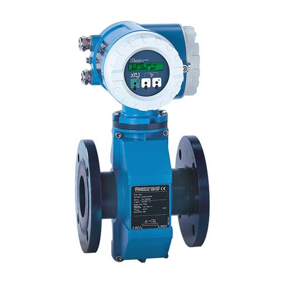
Endress+Hauser PROMAG 33 Operating Manual (127 pages)
Electromagnetic Flow Measuring System
Brand:
Endress+Hauser
| Category:
Measuring Instruments
| Size: 1.48 MB
Table of Contents
Brief Operating Instructions
2
Table of Contents
3
1 Safety Instructions
5
Correct Usage
5
Dangers and Notes
5
Personnel for Installation, Start-Up and Operation
6
Repairs and Dangerous Substances
6
Technical Improvements
6
2 Instrument Identification
7
Promag 33 Transmitter
7
Promag A, H and F Sensors
8
2 Instrument Identification
8
3 Mounting and Installation
9
Base and Supports
9
Transport Instructions (DN ≥ 350/14")
9
Transporting to the Measuring Point
9
Downward Pipe
10
Mounting Location
10
Mounting with a Partly Filled Pipe
10
Partly Filled Pipes
10
Installation of Pumps
11
Vibration
11
Horizontal Mounting
12
Inlet and Outlet Sections
12
Mounting Position
12
Vertical Mounting
12
Nominal Diameter and Flow Rate
13
Adapters
14
Mounting Promag a Sensor
15
Seals / Screw Tightening Torques (Mounting Set)
15
Mounting Promag H Sensor
16
Seals / Screw Tightening Torques
16
Welding the Sensor into the Pipework (Welded Nipple)
16
Mounting Promag F Sensor
17
Screw Tightening Torques (Promag F)
18
Mounting Promag F Sensor
19
Turning the Transmitter Housing and Local Display
19
Connecting Cable
20
Mounting the Transmitter (Remote Version)
20
Wall and Post Mounting
20
4 Electrical Connection
21
Degree of Protection
21
Connecting the Transmitter
22
Connection Diagram for the Transmitter (“HART”)
23
Version with a “HART” Communication Module
23
Connection Diagram for the Transmitter (“RS 485”)
24
Version with a “RS 485” Communication Module
24
Connecting the Cable of the Remote Version
25
Connecting the Transmitter / Sensor Cable
25
Wiring Diagrams for the Remote Version (FS/FL)
26
Remote Version “FS”
26
Remote Version “FL”
26
Cable Specifications
27
Operation in Areas with Severe Electrical Interference
27
Potential Equalisation
28
Potential Equalisation for Lined Pipes with Cathodic Protection
28
Plastic or Lined Piping
29
Equalising Currents in Ungrounded Metal Pipes
29
Grounding in an Area with Severe Interference
29
Connecting E+H Rackbus and Rackbus RS 485
30
Gateway Connection to Pcs or Process-Control Systems
30
Direct Connection to a PC
31
E+H-Rackbus and Rackbus RS 485 Wiring
31
Connecting a Promag 33 to a RS 485 Rackbus
32
Setting the Termination Resistors
32
Connecting HART Communicator
33
Connecting Commubox FXA
33
Promag
33
(Commuwin II Software)
33
Commissioning
34
Display During Start-Up
34
Display and Operating Elements
35
Operation (Operating Matrix)
36
Further Information on Programming
38
Enable Programming (Access Code)
38
Locking Programming
38
Operating Example
39
Operation with the HART Protocol
40
Operating Using the “HART Communicator DXR 275”
40
Operating Using the “Commuwin II” Program
42
Operating Rackbus RS 485
42
Operating Matrix for Rackbus RS 485
44
6 Description of Functions
47
System Units
47
Current Output
49
Pulse / Freq. Output
54
Relays
58
Configuring of Relay Contacts
58
Batching
63
Single-Stage Batching Cycle
63
Two-Stage Batching Cycle
63
Starting / Stopping a Batching Cycle
63
Assign Line
67
Communication
69
Bus Address
69
Protocol
69
Pulse Width → See
69
Functions of the Auxiliary Input
70
Processing Parameters
72
Sensor Data
81
Trouble-Shooting, Maintenance and Repairs
85
Response of the Measuring System on Faults or Alarm
85
Positive Zero Return Not Activated
85
Positive Zero Return Activated
85
Positive Zero Return and Simulation
86
Trouble-Shooting and Remedy
87
Error, Alarm and Status Messages
90
Replacing the Measuring Electrodes
94
Dismantling the Electrode
95
Assembling the Electrode
95
Replacing the Transmitter Electronics
96
Replacing the DAT Module
96
Replacing the Fuse
97
Repairs
97
Spare Parts
97
Maintenance
97
Dimensions Promag 33 a
99
Dimensions of the Process Connections for Promag a
100
Dimensions Promag 33 H
102
Process Connections (Promag H Sensor)
103
Dimensions Promag 33 F (DN 15
104
Dimensions Promag 33 F (DN 350
105
Technical Data
107
Function and System Design
107
Input Variables
107
Output Signal
108
Signal on Alarm
108
Accuracy
108
Measured Error
109
Operating Conditions
109
Installation Conditions
109
Internal Diameter of the Measuring Tube
114
Resistance of the Lining to Vacuum (Standard Version)
115
Functions at a Glance
117
Index
121
Advertisement
Advertisement
Related Products
Endress+Hauser promag 30
Endress+Hauser Promag 300
Endress+Hauser 3-Pack TDLAS
Endress+Hauser promag 31
Endress+Hauser 3Deltapilot M FMB52
Endress+Hauser Promag 500
Endress+Hauser Promag 500-digital
Endress+Hauser Promag 400 Index C
Endress+Hauser Promag
Endress+Hauser promag 50 PROFIBUS-PA
Endress+Hauser Categories
Measuring Instruments
Transmitter
Radar
Switch
Accessories
More Endress+Hauser Manuals
Login
Sign In
OR
Sign in with Facebook
Sign in with Google
Upload manual
Upload from disk
Upload from URL