Endress+Hauser Prosonic S FMU90 Operating Instructions Manual
Flow measurement backwater and dirt detection
totalizers and counters
Hide thumbs
Also See for Prosonic S FMU90:
- Description (217 pages) ,
- Operating instructions manual (186 pages) ,
- Brief operating instructions (56 pages)

Related Manuals for Endress+Hauser Prosonic S FMU90


Summary of Contents for Endress+Hauser Prosonic S FMU90
-
Page 1: Operating Instructions
Operating Instructions Prosonic S FMU90 Flow Measurement Backwater and Dirt Detection Totalizers and Counters BA00289F/00/EN/13.12 71164415 Valid as of software version V 02.01.00... -
Page 3: Table Of Contents
The "display" menu ....75 Parts of the Prosonic S FMU90 ....7 "display"... - Page 4 15.3 Default block configuration ....155 Index ......158 Endress+Hauser...
-
Page 5: Safety Instructions
Safety Instructions Designated use The Prosonic S FMU90 is a transmitter for the ultrasonic sensors FDU90, FDU91, FDU91F, FDU92, FDU93, FDU95 and FDU96. The sensors of the class FDU8x can be connected as well. The transmitter version for level measurements ( ä 9, "Product structure": FMU90 - *1**********) can be applied for different measuring tasks, e.g.:... -
Page 6: Notes On Safety Conventions And Symbols
A connection made to the plant grounding system which may be of type e.g. neutral star or equipotential line according to national or company practice Temperature resistance of the connection cables t >85°C States, that the connection cables must be resistant to a temperature of at least 85 °C (185 °F). Endress+Hauser... -
Page 7: Identification
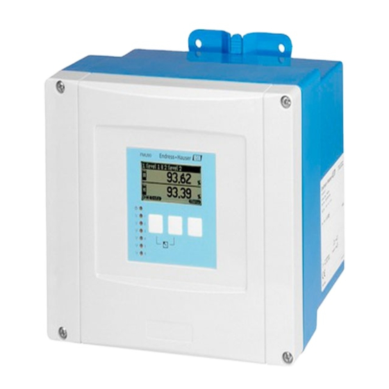
Prosonic S - Flow measurement - HART Identification Identification Parts of the Prosonic S FMU90 2.1.1 FMU90 in the field housing 9 Ma 9 Ma r Co r Co r.-N r.-N … … 4 … 4 … > 60 > 60 °C... -
Page 8: Nameplate (Example)
Marked if a modification nameplate is present Reference to additional safety-relevant documentation Certificate-related data Specification of required temperature resistance of the connection cables Output signal Power supply 10 Serial number 11 Order code (as defined by the product structure) Endress+Hauser... -
Page 9: Product Structure
(*): meaning of the language code: cs: Czech; de: German; en: English; es: Spanish; fr: French; id: Bahasa (Indonesia, Malaysia); it: Italian; ja: Japanese; ko: korean; nl: Dutch; pl: Polish; pt: Portuguese; ru: Russian; th: Thai; zh: Chinese Endress+Hauser... -
Page 10: Scope Of Delivery
The device complies with the applicable standards and regulations as listed in the EC declaration of conformity and thus complies with the statutory requirements of the EC directives. Endress+Hauser confirms the successful testing of the device by affixing to it the CE mark. -
Page 11: Installation
A Mounting help (supplied); can also be used as drilling template B Field housing C Minimum mounting distance The dimensions of the field housing are the same for all instrument versions. To open the housing, a minimum mounting distance of 55 mm (2.17 in) is required on the left. Endress+Hauser... - Page 12 Pipe mounting A mounting plate is available for mounting of the field housing to 1" to 2" pipes ( ä 113, "Accessories"). 3.2.3 Installation L00-FMU90xxx-17-00-00-xx-003 1 Wall mounting with mounting help Endress+Hauser...
-
Page 13: Mounting The Din-Rail Housing
Sum = 1, 2 or 3 (only basic terminal area) (1-3 optional terminal areas) EN 60715 EN 60715 TH 35x7.5/15 TH 35x7.5/15 (1.4x0.3/0.6) (1.4x0.3/0.6) » 0,7 kg (1.54 lbs) » 0,5 kg (1.10 lbs) L00-FMU90xxx-06-00-00-xx-002 L00-FMU90xxx-06-00-00-xx-005 Dimensions in mm (in) Dimensions in mm (in) Endress+Hauser... - Page 14 80, option 3 PROFIBUS DP interface 0 (no) inputs for external switches and feature 90, option B 0 (no) external temperature sensorr Sum = Sum = 2 => 104 x 150 x 140 mm (4.09 x 5.91 x 5.51 in) Endress+Hauser...
- Page 15 • The cables may not be laid in the proximity to frequnecy converters. 3.3.3 Mounting EN 60715 TH 35x7.5/15 (1.4x0.3/0.6) L00-FMU90xxx-17-00-00-xx-001 A Attaching the instrument to the rail B Detaching the instrument from the rail Endress+Hauser...
-
Page 16: Mounting The Remote Display And Operating Module
Cut an opening of 92 x 92 mm (3.62 x 3.62 in) into the intended mounting position (e.g. cabinet door). Insert the remote display module into the opening and fix the retainers as shown in the following figure: L00-FMU90xxx-17-00-00-xx-002 Endress+Hauser... -
Page 17: Mounting Of The Sensors
• For the field housing: Are the cable glands tightened correctly? • Is the instrument securely mounted to the DIN rail or the mounting help (visual inspection)? • For the field housing: Are the screws of the terminal compartment cover securely tightened (visual inspection)? Endress+Hauser... -
Page 18: Wiring
• M25x1.5 (1 opening) The required number and types of cable entries depend on the application at hand. The prestamped openings can be removed by a suitable tool (e.g. knife or boring bit) or by punching them out cautiously. Endress+Hauser... - Page 19 • The pictures show the smallest housing version but are valid for the larger versions as well. • If the instruments are mounted next to each other and if the sensor cables run in parallel, the synchronization terminals (39 and 40) must be interconnected ( ä 20 "Terminal assignment" and ä 30 "Synchronization line"). Endress+Hauser...
-
Page 20: Terminal Assignment
Terminals of the Prosonic S (the terminals depicted in grey are not present in every instrument version) Basic terminal area Optional terminal areas (present if the respective option has been selected in the product structure) Note! The depicted switching states of the relays refer to the de-energized state. Endress+Hauser... - Page 21 0: < 8 V or 81 and 82 interconnected 1: > 16 V or 81 and 82 not interconnected temperature input ä 27, "Connection of a temperature sensor" 83, 84, 85 temperature input: • PT100 • FMT131 (Endress+Hauser) Endress+Hauser...
- Page 22 Service interface for connection of a PC/Notebook via Commubox FXA291 Locking switch Term. Bus termination (only applicable for instruments with PROFIBUS interface) Address Bus address (only applicable for instruments with PROFIBUS interface) Warning! On wiring, the supply voltage must be switched off. Endress+Hauser...
-
Page 23: Sensor Connection
D Grounding at the transmitter FMU90 1 Screen of the sensor cable 2 Terminal box 3 Screen of the extension cable Colours of the strands: YE = yellow; BK = black; RD = red; BU = blue; BN = brown; GNYE = green-yellow Endress+Hauser... - Page 24 If the terminal box is installed in explosion hazardous areas, all applicable national guidelines must be observed. Suitable extension cables can be obtained from Endress+Hauser ( ä 113, "Accessories") Alternatively, cables with the following properties can be used: • Number of cores according to the connection diagram (see above) •...
-
Page 25: Connection Of The Sensor Heater (For Fdu90/Fdu91)
Display HART 0/4…20mA FDU- Sensor Relay A B C D B BN D BU 24 VDC FDU90 FDU91 L00-FMU90xxx-04-00-00-xx-013 1 Terminal module for the sensor heater 2 External power supply unit 3 Brown strand (BN) 4 Blue strand (BU) Endress+Hauser... - Page 26 Display HART 0/4…20mA FDU- Sensor Relay FDU90 FDU91 24 VDC L00-FMU90xxx-04-00-00-xx-014 Note! The terminal module supplied with the sensor can also be used for connection of the supply voltage. For the terminal assignment on this module ä 25. Endress+Hauser...
-
Page 27: Connection Of External Switches (For Fmu90-********B***)
The maximum short-circuit current at 24 V is 20 mA. Connection of a temperature sensor The Prosonic S FMU90 transmitter has an optional input for an external temperature probe (in the product structure: feature 90 "Additional input", option B). The following probes can be connected: •... - Page 28 Wiring Prosonic S - Flow measurement - HART 4.6.1 FMT131 (Endress+Hauser) (connectable to FMU90-********B***) FMU90 FMU90 FMU90 YEGN YEGN YEGN FMT131-R FMT131-J FMT131-J L00-FMU90xxx-04-00-00-xx-019 A Non-Ex area (FMT131-R) black B Ex area (FMT131-J) with grounding in the FMU90 yellow C Ex area (FMT131-J) with grounding at a terminal box...
-
Page 29: Shortening The Sensor Cable
GNYE L00-FMU90xxx-04-00-00-xx-015 Colours of the strands: YE = yellow; BK = black; RD = red; BU = blue; BN = brown; GNYE = green-yellow Note! The blue (BU) and brown (BN) strands are only present for sensors with heater. Endress+Hauser... -
Page 30: Synchronization Line
The screen must be connected to ground • Instruments of the Prosonic FMU86x family can be connected to the synchronization line as well. In this case a maximum of 10 instruments can be connected to each synchronisation line. Endress+Hauser... -
Page 31: Connection Of The Separate Display And Operating
For the version of the Prosonic S with a separate display for panel mounting, a pre-assembled connecting cable (3 m (9.8 ft)) is supplied. The cable must be connected to the display plug of the Prosonic S. Note! Minimum diameter for cable bushing: 20 mm (0.79 in). Endress+Hauser... -
Page 32: Potential Equalization
ä 23. The metallic terminal block (1) in the field housing can be used for this. L00-FMU90xxx-04-00-00-xx-006 Example Sync Service Fuse Display HART 0/4…20mA FDU- Sensor Relay GNYE FDU91F/93/95/96 90 … 253 VAC (FDU83/84/85/86) 10,5 … 32 VDC L00-FMU90xxx-04-00-00-xx-007 1 The wire is already connected on delivery Endress+Hauser... -
Page 33: Post-Connection Check
• For the field housing: Are the cable glands tight and is the cover of the terminal compartment securely closed? • If auxiliary energy is switched on: Does a display appear on the display module (if available) and does the green LED light up? Endress+Hauser... -
Page 34: Operation
Display and operating elements FMU90 L00-FMU90xxx-07-00-00-xx-002 1 Softkey symbol 2 Key 3 LEDs indicating the switching states of the relays 4 LED indicating the operating state 5 Display symbols 6 Value of the parameter, including unit 7 Name of the parameter Endress+Hauser... - Page 35 An error is detected. The measurement is interrupted. The measured value assumes the value specified by the user (parameter "output on alarm"). supply voltage missing LEDs for the relays (pos. 3 in the figure) yellow The relay is activated. The relay is de-activated (idle state). Endress+Hauser...
- Page 36 • While editing a parameter: Exit the editing mode without accepting the changes. • Within the navigation: Move upwards to the previous layer of the menu. Increase contrast Increases the contrast of the display module. Decrease contrast Decreases the contrast of the display module. Endress+Hauser...
- Page 37 If the parameter set occurs only once wihtin the Prosonic S, "X" is indicated at this position. • The last three digits (3) specify the individual parameter sets within the submenu. Depending on the instrument version, the installation environment and the selected operating mode, some of the submenus may not be present. Endress+Hauser...
- Page 38 • when entering a selection parameter, the associated selection list appears (see below: "Editing a parameter with selection list"). L00-FMU90xxx-07-00-00-en-044 • when entering a numerical or alphanume- rical parameter, the text and number editor appears (see below: "Entering numbers and characters"). Endress+Hauser...
- Page 39 Prosonic S - Flow measurement - HART Operation Navigation within the menu (Example) L00-FMU90xxx-19-00-00-en-050 Endress+Hauser...
- Page 40 After pressing the key, a list of all currently present errors appears. Note: Depending on the configuration, the appearance of the measured value display may be differemt from the example in the figure. The difference between"Warning" and "Alarm" Chap. 10.1 Endress+Hauser...
- Page 41 This level is reached if the softkey symbols U and T appear. “distance unit” parameter set L00-FMU90xxx-19-00-00-yy-039 Note! If necessary, you can return to the previous level of the menu by pressing Endress+Hauser...
- Page 42 The editing method depends on the type of parameter (selection list, numeric or alphanumeric parameter). For details refer to the following sections. L00-FMU90xxx-19-00-00-en-040 Note! If necessary, you can exit the parameter and parameter set by pressing Endress+Hauser...
- Page 43 The software key symbols U and T reappear and you can switch to the next parameter set. L00-FMU90xxx-19-00-00-en-041 Note! before ✓ you can quit the parameter without accepting your changes. By pressing Endress+Hauser...
- Page 44 If all relevant digits have been entered: Press S or O, until appears at the cursor. Press to store the complete value in the device. Press the left and middle keys simultane- ously in order to quit the parameter. L00-FMU90xxx-19-00-00-yy-042 Endress+Hauser...
- Page 45 Escape: The editor is closed. The parameter maintains its former value. The same behavior can be achieved by pressing the left and the middle key simultaneously ( L00-FMU90xxx-19-00-00-yy-045 Next digit: The cursor moves on to the next digit. L00-FMU90xxx-19-00-00-yy-046 Previous digit: The cursor moves back to the previous digit. Endress+Hauser...
- Page 46 • from a parameter to the parameter set • from the parameter set to the submenu • from the submenu to the main menu • from the main menu to the measured value display L00-FMU90xxx-19-00-00-en-048 Endress+Hauser...
-
Page 47: Operation Via Endress+Hauser Operating Tool "Fieldcare
Prosonic S - Flow measurement - HART Operation Operation via Endress+Hauser operating tool "FieldCare" L00-FMU90xxx-19-00-00-en-087 Operation via the FieldCare is similar to the operation via the display module. • The operating menu can be found in the navigation bar (1). - Page 48 The key has been locked by a key combination. It can only be unlocked by pressing all three keys simultaneously. • switch locked The instrument has been locked by the switch in the terminal compartment. It can only be unlocked by this switch. Endress+Hauser...
-
Page 49: Reset To The Default Configuration
To realize this, the parameter "zero distance" is fine adjusted. After a reset the value for the zero distance has to be re-parameterized in the service menu according to the data on the associated 5- point linearity protocol for the FDU9x sensor. Please contact the Endress+Hauser service. Note! •... -
Page 50: Commissioning
• Relay 4 (for instruments with 6 relays) • Relay 5 (for instruments with 6 relays) • Relay 6 (for instruments with 6 relays) 6.1.2 Typical block configurations 1-channel flow measurement Display Current output 1 Sensor 1 Flow 1 +HART Alarm Relay 1 FDU9x L00-FMU90xxx-19-00-00-en-090 Endress+Hauser... - Page 51 Alarm Relay 1 FDU90 (downstream water) L00-FMU90xxx-19-00-00-en-093 Note: The backwater alarm relay must be configured by the user. It is not part of the default configuration. Note! By default, relay 1 is always configured to be the alarm relay. Endress+Hauser...
-
Page 52: First Setup
By pressing you can return to the previous parameter (e.g. in order to correct the value). All these parameters can also be changed at a later point of time in the "device properties/operating parameters" and "device properties/language" parameter sets. Endress+Hauser... -
Page 53: Preparing The Basic Setup
• the backwater detection ("backwater" submenu) • the flow counters ("flow counter" submenu) The operating mode is selected during the first setup. Nevertheless, it can be changed at any time if required ("device properties" menu, "operating params" submenu, "operating mode" parameter set). Endress+Hauser... -
Page 54: Calibration Of A Flow Measurement
(N = 1 or 2) (N = 1 or 2) level displays the currently measured level (for checking purposes) distance displays the currently measured distance between the reference point of the sensor and the liquid surface (for checking purposes) Endress+Hauser... -
Page 55: Endress+Hauser
(N = 1 or 2) status Used to enable, disable or delete a mapping Chap. 6.7 Parametrization of the counters (in the operating menu: "flow/flowcounter") The type of linearisation determines the relationship between the measured level and the flow. Endress+Hauser... - Page 56 Indicates the type of the automatically detected sensor. This option is only available if two level measurements have been calibrated. This is only possible for the "leve+flow" operating mode and a two channel inst- rument. if the sensor is of the type FDU9x. Endress+Hauser...
-
Page 57: Endress+Hauser
It is used to select the type of flume or weir. After the selection, a second list appears with differnt sizes of the flume or weir . When you have confirmed your selection, the Prosonic S returns to the "linearization" function. Tables of the flume and weir parameters can be found in the Appendix. Endress+Hauser... -
Page 58: Endress+Hauser
The table is not used. A flow value is not calculated. "alpha", "beta", "gamma" and "C" These parameters are available for the "formula" linearization type. They are used to specify the parameters of the flow formula: + h Q = C(h Endress+Hauser... -
Page 59: Endress+Hauser
L00-FMU90xxx-19-00-00-yy-027 Example: Khafagi-Venturi flume E: empty distance; D: measured distance; L: level For weirs, the zero point is the lowest point of the weir crest: FDU 91 L00-FMU90xxx-19-00-00-yy-028 Example: Triangular weir E: empty distance; D: measured distance; L: level Endress+Hauser... -
Page 60: Endress+Hauser
If the displayed value does not match the real level, it is recommended to check the empty calibration. "sensor" Displays the currently measured distance D between the reference point of the sensor and the liquid surface. If the displayed value does not match the real distance, it is recommended to perform an interference echo suppression. Endress+Hauser... -
Page 61: Endress+Hauser
0%). 6.4.7 "flow N check value" (N = 1 or 2) flow 1 check value F1006 distance: check distance: L0000 flow 1 check value distance: D display display check distance: > D display < D display L00-FMU90xxx-19-00-00-de-031 Endress+Hauser... -
Page 62: Endress+Hauser
Use this parameter to specify the range of the mapping curve. Normally, a suitable value has already been entered automatically. Nevertheless, you can change this value if required. "start mapping" Select "yes" in this parameter in order to start the mapping. When the mapping is finished, the state is automatically changed to "enable map". Endress+Hauser... -
Page 63: Endress+Hauser
• delete map Choose this option in order to delete the mapping. It can not be reactivated again and the instrument uses the preprogrammed default mapping. Endress+Hauser... -
Page 64: Calibration Of Backwater And Dirt Detection
The ultrasonic sensor for the measurement of the downstream water level should be installed at a sufficient distance from the discharge of the flume. The measuring point must be selected in such a way that the surface of the water is calmed down and the level is not influenced by the flume anymore. Endress+Hauser... - Page 65 • Value not correct: go back to step 7 ("backwater check value") flow 1 displays the currently measured flow status Used to enable, disable or delete a mapping Configuration of the backwater and dirt alarm relay, Chap. 8.2 Endress+Hauser...
- Page 66 The default setting is B = 0,8. This is the optimum value for Venturi flumes. To ensure reliable measurement it should not be exceeded. In the "relay/controls" menu, one of the relays can be defined to be the backwater alarm relay. Endress+Hauser...
- Page 67 • the current flow Q Use these values to check the flow calibration as well as the calibration of the backwater and dirt detection. In the "relay/controls" menu, one of the relays can be defined to be the dirt alarm relay Endress+Hauser...
-
Page 68: Calibration For Simultaneous Level And Flow Measurement With One Sensor
Note! It is recommended to perform the interference echo suppression when calibrating the level measurement. This suppression is automatically valid for the flow measurement as well. Therefore, the interference echo suppression can be skipped when calibrating the flow measurement. Endress+Hauser... -
Page 69: Parametrization Of The Counters
• stop: Counting is interrupted. Chap. 6.7.5 daily counter N external reset allocate external input (digin) for reset (only for instruments with external start allocate externao input (digin) for start and stop of the counter external switch inputs: FMU90-********B***) Endress+Hauser... - Page 70 • flow 1+2, Q1 + Q2, (for 2-channel instruments only) "counting unit" Use this parameter to select the unit for the flow volume. Selection: • m • l • hl • igal • usgal • barrels • inch • ft • USmgal • Ml Endress+Hauser...
- Page 71 "value max. size" option in the "type" parameter ( ä 75). "reset" (only for the daily counters) Use this parameter to reset the counter to "0". Selection: • no (default) "value" and "overflow" retain their values. • yes "value" und "overflow" are reset to "0". Endress+Hauser...
- Page 72 The Prosonic S continues counting. It uses the flow value which was present at the moment the error occured. • actual value The Prosonic S continues counting. It uses the current flow value (although its reliability is no longer ensured). Endress+Hauser...
- Page 73 • ... • ext. digin 4 "external start" This parameter allocates one of the external switch inputs to the counter by which it can be started. Selection: • disabled • ext. digin 1 • ... • ext. digin 4 Endress+Hauser...
-
Page 74: Envelope Curve Display
Additional parameters are available for optimization of the measuring point. They can be parametrized as required. A detailed description of all instrument parameters is given in the operating manual BA00290F/00, "Prosonic S FMU90 - Description of Instrument Functions". A PDF file of this document is available from •... -
Page 75: The "Display" Menu
Up to 6 values can be displayed on three alternating pages. Each pages contains two values. "time" This parameter is used for the options "value max. size" and "alter 3x2 values". It specifies the time after which the next page appears. Note! To change to the next page immediately, press Endress+Hauser... -
Page 76: Display Format
Use this parameter to select the separation character for the representation of decimal numbers. Selection: • point (.) (Default) • comma (,) "customized text" Determines if "text 1" to "text 6" from the "calibration display" parameter set are displayed. Selection: • no (Default) • yes Endress+Hauser... -
Page 77: Back To Home
"back to home" Use this parameter to specify the return time. If no entry is made during the specified time, the display returns to the measured value display. • Range of values: 3 ... 9999 s • Default: 900 s Endress+Hauser... -
Page 78: The "Relay/Controls" Menu
N (N = 1 - 6) switch delay Define the switch delay (Default: 0s). invert Select if the relay signal is to be inverted (default: no) error handling Define the reaction of the relay in the case of an error. Endress+Hauser... - Page 79 "sensor management/FDU sensor N". Possible temperatures are: • sensor temperature • average of sensor temperature and temperature of an external temperature sensor • temperature of an external temperature sensor Endress+Hauser...
- Page 80 The relay is de-energized if the measured value is above the upper or below the lower switching point. Additionally, a hystersis can be defined, which affects both switching points. • out of band For this limit type, an upper and a lower switching point have to be defined. Endress+Hauser...
- Page 81 Define the switching points in these parameters. They have the same unit as the measured value. " Caution! After a change of the "unit level" or "flow unit" the switching points have to be checked and adjusted if required. Endress+Hauser...
- Page 82 The relay switches according the the currently measured value (although its reliability is not ensured). • hold (default) The current switching state of the relay is maintained. • switch on The relay is energized. • switch off The relay is de-energized. Endress+Hauser...
-
Page 83: Configuration Of An Alarm Or Diagnostic Relay
Use this parameter to select the relay you are going to configure. Selection: • All relays of the instrument version at hand Note! If a function has already been allocated to one of the relays, the name of this function is displayed next to the relay number. Endress+Hauser... - Page 84 • defective external temperature sensor • Accumulated alarm: defective temperature sensor • overtemp. sensor 1/2 • Accumulated Alarm: overtemp. • safety distance channel 1/2 • Accumulated Alarm: safety distance • pump alarm • pump operation This is the default setting for relay 1. Endress+Hauser...
- Page 85 The switching direction of the relay is not inverted. The relay switches as described in the above sections. • yes The switching direction of the relay is inverted. The states "energized" and "de-energized" are interchanged as compared to the above description. Endress+Hauser...
-
Page 86: Configuration Of A Time Pulse Relay
Initially, it contains the "function" parameter only. To configure a time pulse relay, proceed according to the following steps: Select the "function" parameter. The "select function" screen appears. Select "time pulse". The "function" selection list appears. Confirm you choice by selecting "time pulse" again. Endress+Hauser... - Page 87 "error handling" Use this parameter to specify the reaction of the relay in the case of an error. Selection: • actual value The Prosonic S continues generating pulses. • stop No pulses are generated in the case of an error. Endress+Hauser...
-
Page 88: Configuration Of A Counting Pulse Relay
Use this parameter to select the relay you are going to configure. Selection: • All relays of the instrument version at hand Note! If a function has already been allocated to one of the relays, the name of this function is displayed next to the relay number. Endress+Hauser... - Page 89 • i gal • barrels "pulse value" Use this parameter to specify the flow volume after which a pulse is generated. Default: 100 m "pulse width" Use this parameter to specify the width of each pulse. Default: 200 ms Endress+Hauser...
- Page 90 "pulse counter" and "overflow" are reset to "0". m /h, ft /s, … m , ft , … 1 2 3 5 6 7 8 9 L00-FMU90xxx-19-00-00-yy-064 A: flow; B: pulse width; C: relay energized; D: relay de-energized; E: pulse value; F: pulse counter Endress+Hauser...
- Page 91 These parameters can be used for dual range (nested) flumes in order to limit the pulses to the lower or upper part of the flume. For details refer to the manual "Prosonic S - Description of the instrument functions", BA00290F/00. Endress+Hauser...
- Page 92 The currently measured flow value is used (although its reliability is not ensured). • hold The counter uses the flow value which was present when the error occurred. • stop No pulses are generated in the case of an error. Endress+Hauser...
-
Page 93: The "Output/Calculations" Menu
OX001 current output 1 (current output 2) After this selection, additional submenus appear, which can be used to configure the output: current output 1 O1302 allocat./calculat extended calibr. HART settings simulation Endress+Hauser... -
Page 94: The "Allocation/Calculations" Submenu
• average level: (level1 + level2)/2 • level 1-2 • level 2-1 • level 1+2 • average flow • flow 1-2 • flow 2-1 • flow 1+2 • backwater ratio downstream/upstream • rake control ratio downstream/upstream "output current" Displays the output current (mA). Endress+Hauser... -
Page 95: The "Extended Calibration" Submenu
A: current span = 4-20 mA; B: current span = 0-20 mA; C: current span = fixed current HART; D: mA value "mA value" (only available for "current span" = "fixed current HART") Specifies the value of the fixed current. • range of values: 3,6 - 22 mA • default: 4 mA Endress+Hauser... - Page 96 The threshold is switched off. Currents less than 4 mA may occur. • on The threshold is switched on. The current never falls below 4 mA. [mA] [mA] 100 [%, ...] 100 [%, ...] L00-FMU90xxx-19-00-00-yy-067 A: 4mA threshold off; B: 4mA threshold on Endress+Hauser...
- Page 97 Specifies the measured value for which the current is 0 or 4 mA (depending on the selected current span). "turn down 20 mA" (only for "current turn down" = "on") Specifies the measured value for which the current is 20 mA. [mA] 100 [%, ...] L00-FMU90xxx-19-00-00-yy-068 A: turn down 4mA ; B: turn down 20 mA Endress+Hauser...
-
Page 98: Hart Settings" Submenu (Only For Current Output 1)
"mA value" parameter of the "mode current" parameter set (see above). "no. of preambles" Specifies the number of preambles for the HART protocol. For lines with communication problems a slight increase of this value is recommended. "short TAG HART" in preparation Endress+Hauser... - Page 99 Specifies the output damping by which a change of the measured value is attenuated. After a surge of the measured value it takes 5 x till the HART value has adopted the new value. • range of values: in preparation • default: 1 s Endress+Hauser...
-
Page 100: Simulation" Submenu
The instrument is in the simulation mode. No measured value is transmitted to the output. Instead, the current output assumes the value specified in the "simulation value" subfunction. "simulation value" (only for "simulation" = "on") Specifies the value of the simulated output current (in mA). Endress+Hauser... -
Page 101: Troubleshooting
• MAX: 110%, 22 mA • MIN: -10%, 3,6 mA Alarm (A) • Hold: last value is held • user-specific value continuous Additionaly, an error message appears on the display. The instrument continues to measure. Warning (W) An error message is displayed. flashing Endress+Hauser... -
Page 102: Error Codes
A 00 111 electronics defective switch instrument off/on; A 00 112 if the error persists: A 00 114 call Endress+Hauser service A 00 115 A 00 116 download error repeat download A 00 117 hardware not recognised after exchange... - Page 103 W 02 703 Operating hours alarm pump 3 ctrl 2 Reset operating hours W 01 704 Operating hours alarm pump 4 ctrl 1 Reset operating hours W 02 704 Operating hours alarm pump 4 ctrl 2 Reset operating hours Endress+Hauser...
- Page 104 Check the units of the respective basic calibrations value, sum, difference or rake control (s. "level" or "flow" menu) A 00 832 After a repair of the pump the pump control must be reset (BA00290F/00) or the FMU90 must be switched off and Endress+Hauser...
-
Page 105: Possible Calibration Errors
Echo loss (Error E@@641) Check all settings in the "application parameters" parameter set. b. if possible: choose better mounting position and/or larger sensor. Align the sensor membrane parallely to the product surface (especially for solid applications). Endress+Hauser... -
Page 106: Envelope Curve Display
– Press the left key to zoom out the envelope curve. The Floating Average Curve (FAC) is represented by a dotted line as well. The echo quality is the distance (in dB) between the peak of the echo and the Floating Average Curve (FAC). Endress+Hauser... - Page 107 – Press the middle key to move the envelope curve to the right. – Press the left key to move the envelope curve to the left. L00-FMU90xxx-19-00-00-en-085 Quitting the envelope curve display Press to quit the envelope curve display. Endress+Hauser...
- Page 108 Click on "read curve" to display a single curve. Click on "cyclic read" to display the curves cyclically. Select the curves you want to check in the "Curves" window: - Envelope Curve - Map (= mapping of the interference echo suppression) - FAC (= Floating Average Curve) Endress+Hauser...
-
Page 109: Software History
07.2009 V 02.01.00 Integration of the FDU90 sensor • for level measurements: BA288F/00/en/07.09 02.2010 V02.01.01 Integration Temperaturplausibilisierung 71098292 • BA00288F/00/EN/13.12 05.2011 V02.01.03 Improvement temperature plausibility; 71164411 flow counter limitation; bugfix • for flow measurements: BA289F/00/en/07.09 71098296 • BA00289F/00/EN/13.12 71164415 Endress+Hauser... -
Page 110: Maintenance
11.2 Repairs The Endress+Hauser repair concept assumes that the measuring devices have a modular design and that customers are able to undertake repairs themselves ä 111, "Spare Parts". For more information on service and spare parts, If you have any questions, please contact your Endress+Hauser sales representative. -
Page 111: Spare Parts
Select the required spare parts (You may also use the overview drawing on the right side of the screen.) When ordering spare parts, always quote the serial number indicated on the nameplate. As far as necessary, the spare parts also include replacement instructions. Endress+Hauser... -
Page 112: Return
The measuring device must be returned if repairs or a factory calibration are required, or if the wrong measuring device has been ordered or delivered. According to legal regulations, Endress+Hauser, as an ISO-certified company, is required to follow certain procedures when handling returned products that are in contact with medium. -
Page 113: Accessories
• for 1" - 2" tubes • Dimensions: 210 x 110 mm (8.27 x 4.33 in) • Material: 316Ti (1.4571) • fixing clips, screws and nuts are supplied • Order code: 52024478 L00-FMU90xxx-00-00-00-xx-001 1 Mounting help of the field housing Endress+Hauser... -
Page 114: Mounting Bracket
4 (0.16) 20 (0.8) (2.17) (3.94) 130 (5.12) 150 (5.91) mm (in) L00-FMUxx-00-00-00-xx-005 Height Material Order Code 700 (27.6) galv. steel 919791-0000 700 (27.6) 316Ti (1.4571) 919791-0001 1400 (55.16) galv. steel 919791-0002 1400 (55.16) 316Ti (1.4571) 919791-0003 mm (in) Endress+Hauser... -
Page 115: Adaption Plate For Remote Display
(3.78 x 3.78 in)). Can be used to replace the FMU86x remote display or DMU2160/2260. Order Code: TSPFU 0390 Please contact your Endress+Hauser sales representative. 12.7 Overvoltage protection (in IP66 housing) • Overvoltage protection for the mains voltage and up to 3 signal outputs •... -
Page 116: Overvoltage Protection Haw562
3 - n.c. 1x Measurement signal, 1x HAW562-AAA Power supply L / + N / - Cable shield 24 V: HAW562-AAB 230 V: HAW562-AAC Prosonic S G09-HAW562xx-04-10-01-en-002 Level measurement with 1 Prosonic FDU9x level sensor, version 4 to 20 mA HART Endress+Hauser... - Page 117 2x HAW562-AAA Power supply L / + N / - Cable shield 65 A(N) 66 B(P) 24 V: HAW562-AAB 230 V: HAW562-AAC Prosonic S G09-HAW562xx-04-10-01-en-001 Level measurement with 2 Prosonic FDU9x level sensors, version 4 to 20 mA HART Endress+Hauser...
-
Page 118: Extension Cable For Sensors
(-40 to +221 °F) • FDU95 • FDU95 Silicone (-40 to +150 °C) Li2G2G 2x(0.75)D+1x0.75 71027745 • FDU96 (-40 to +302 °F) • FDU90/FDU91 LiYY 2x(0.75)D+2x0.75 71027746 with heater Total length (sensor cable + extension cable): up to 300 m (984 ft) Endress+Hauser... -
Page 119: 12.10 Temperature Sensor Fmt131
10 m/ 32 ft 15 m/49 ft 20 m/65 ft 25 m/82 ft 30 m/98 ft w/o cable, gland Pg16, IP66 ... m ... ft Marking Tagging (TAG) FMT131 - complete product designation Weather protection cover for FMT131 Order code: 942046-0000 Endress+Hauser... -
Page 120: Technical Data
The sensors FDU83, FDU84, FDU85 and FDU86 with an ATEX, FM or CSA certificate are not certified for connection to the transmitter FMU90. External limit switches Optionally, the Prosonic S FMU90 has four inputs for external limit switches (FMU90- (option) ********B***). - Page 121 Prosonic S - Flow measurement - HART Technical Data External temperature sensor Optionally, the Prosonic S FMU90 has an input for an external temperature sensor (FMU90- ********B***). Connectable sensors • Pt100 (3-wire or 4-wire connection) A Pt100 with 2-wire connection may not be used due to its insufficient accuracy.
-
Page 122: Power Supply
Measuring uncertainty ±0,2 % of the maximum span of the sensor Typical accuracy ±2 mm (0.08 in) + 0.17 % of the measured distance Measured value resolution 1 mm (0.04 in) with FDU90/FDU91 according to NAMUR EN 61298-2 after calibration Endress+Hauser... - Page 123 (hydrochloric acid, sulfuric acid, ...), dilute bases (caustic soda, ...), oils, greases, slurries, pastes, ... High vapor pressures or outgassing media (ethanol, acetone, ammonia, ...) can influence the accuracy. If conditions like these are present, please contact your Endress+Hauser sales representative. 13.1.5...
- Page 124 Housing for DIN rail ( ä 13 "Dimensions of the DIN-rail housing") separate display and operating approx. 0.5 kg (1.10 lbs) module Materials Part Material Housing bracket PC-FR Field housing PC-FR Housing for DIN rail PBT-GF For details see Technical Information TI00397F/00. Endress+Hauser...
- Page 125 Prosonic S - Flow measurement - HART Technical Data Endress+Hauser...
-
Page 126: Operating Menu
FX101 totalizer daily counter 1 … F1104 F1102 F1103 daily counter daily counter daily counter daily counter daily counter daily counter … allocation: value: error handling: daily counter none overflow: (reset:) counting unit: 1) not available for totalizors L00-FMU90xxx-19-02-01-de-106 Endress+Hauser... - Page 127 1 external reset: - disabled ext. digin 1 ext. digin 4 fieldbus DO1 1) only for device version with additional switch inputs (FMU90-********B***) fieldbus DO10 2) only for PROFIBUS devices external start: not available for totalizors L00-FMU90xxx-19-02-02-en-106 Endress+Hauser...
-
Page 128: Safety Settings
Default: 60s Default: 0,0 m hold max. ramp %/min ramp level1: (delay sensor 2) (saf. dist. sen 2) hold customer spec. value level1: user specific output value 1 alarm (output 2:) (level 2:) 1) only for HART devices L00-FMU90xxx-19-03-01-en-106 Endress+Hauser... - Page 129 1 def. temp.sens 1: warning Default: 5s warning warning self holding alarm alarm alarm (max.temp. Sen. 1:) (def.temp. sens 2:) (reset sensor 1:) (overtemp. sen 2:) (in saf. dist. s 2:) (max.temp. Sen. 2:) (reset sensor 2:) L00-FMU90xxx-19-03-02-en-106 Endress+Hauser...
-
Page 130: Relay/Controls
R201E field bus function none DO10 R1001 relay/controls relay simulation RX120 relay simulation relay 1: R2106 relay 2: relay 2 … simulation: simulation value: switch off switch on L00-FMU90xxx-19-08-01-en-106 Endress+Hauser... - Page 131 100% default: 200 ms R2103 R2104 R2104 R2104 relay 2 relay 2 relay 2 relay 2 function: invert: invert: invert: diagnostics allocation 1: none echoloss sen 1 … allocation 2: none echoloss sen 2 … L00-FMU90xxx-19-08-02-en-106 Endress+Hauser...
-
Page 132: Output/Calculations
1 level 1 level 1 default: 5 … … … short TAG HART: output damping 2: output damping 3: output damping 4: default: 0 s default: 0 s default: 0 s O1302 current output 1 simulation: simulation value: L00-FMU90xxx-19-05-01-en-106 Endress+Hauser... -
Page 133: Device Properties
2) only for operating modes "level" and "level +flow" tag marking D1102 tag marking output 1: output 2: device marking: D1103 language language language: English … D1104 password/reset password/reset reset: (s. manual) code: (s. manual) status: 1) only for HART instruments L00-FMU90xxx-19-06-01-en-106 Endress+Hauser... -
Page 134: System Information
I1405 I1405 I1406 diagnostics operating hours actual distance act. meas. value appl. parameter echo quality sen. operation hours: act. distance 1: level 1: sensor 1: echo quality 1: act. distance 2: flow 1: (sensor 2:) (echo quality 2:) L00-FMU90xxx-19-07-01-en-106 Endress+Hauser... - Page 135 Prosonic S - Flow measurement - HART Operating menu IX106 IX107 IX108 software version dev. version DD version software version: dev. rev.: DD version: IX11A* IX10B IX10B … current output 2 relay 1 relay N output: function: function: 1) only for HART instruments L00-FMU90xxx-19-07-02-en-106 Endress+Hauser...
-
Page 136: Display
D1025 external digin external digin external digin 2 invert: external digin 3 external digin 4 1) only for device version with additional switch inputs and connected external temperature sensorr (FMU90-********B***) 2) only for PROFIBUS devices L00-FMU90xxx-19-10-01-en-106 Endress+Hauser... -
Page 137: Appendix
800 (31.5) 320 (12.6) 600 (23.6) 1024 Khafagi-Venturi QV 310 1000 (39.4) 400 (15.7) 800 (31.5) 1982 Khafagi-Venturi QV 313 1300 (51.2) 520 (20.5) 950 (37.4) 3308 Khafagi-Venturi QV 316 1600 (63.0) 640 (25.2) 1250 (49.2) 6181 mm (in) Endress+Hauser... - Page 138 3812 Khafagi-Venturi QV313 1350 (53.1) 5807 Khafagi-Venturi QV 316 1800 (70.9) 11110 Note! After selecting the type of flume, Q can be adjusted to the flow conditions. Q defines the flow at which the output current is 20 mA. Endress+Hauser...
- Page 139 1318.9 ISO-Venturi 480 800 (31.5) 480 (18.9) 800 (31.5) 1862.5 mm (in) Note! After selecting the type of flume, Q can be adjusted to the flow conditions. Q defines the flow at which the output current is 20 mA. Endress+Hauser...
- Page 140 BST Venturi 18" 18" 480 (18.9) 925.7 BST Venturi 30" 30" 840 (33.1) 3603 Note! After selecting the type of flume, Q can be adjusted to the flow conditions. Q defines the flow at which the output current is 20 mA. Endress+Hauser...
- Page 141 6.0 ft 780 (30.7) 10951 Parshall 8 ft 8.0 ft 780 (30.7) 14767 Note! After selecting the type of flume, Q can be adjusted to the flow conditions. Q defines the flow at which the output current is 20 mA. Endress+Hauser...
- Page 142 Palmer-Bowlus 27" 27" 540 (21.3) 1625.58 Palmer-Bowlus 30" 30" 600 (23.6) 2136.47 Note! After selecting the type of flume, Q can be adjusted to the flow conditions. Q defines the flow at which the output current is 20 mA. Endress+Hauser...
- Page 143 • In the "width" parameter, the width of the weir can be adjusted. The corresponding change of the flow curve is automatically performed by the Prosonic S. • After selecting the type of weir, Q can be adjusted to the flow conditions. Q defines the flow at which the output current is 20 mA. Endress+Hauser...
- Page 144 • In the "width" parameter, the width of the weir can be adjusted. The corresponding change of the flow curve is automatically performed by the Prosonic S. • After selecting the type of weir, Q can be adjusted to the flow conditions. Q defines the flow at which the output current is 20 mA. Endress+Hauser...
- Page 145 • In the "width" parameter, the width of the weir can be adjusted. The corresponding change of the flow curve is automatically performed by the Prosonic S. • After selecting the type of weir, Q can be adjusted to the flow conditions. Q defines the flow at which the output current is 20 mA. Endress+Hauser...
- Page 146 1527.8 NFX Rect WThr T0 1000 (39.4) 600 (23.6) 2933.8 mm (in) Note! After selecting the type of weir, Q can be adjusted to the flow conditions. Q defines the flow at which the output current is 20 mA. Endress+Hauser...
- Page 147 • In the "width" parameter, the width of the weir can be adjusted. The corresponding change of the flow curve is automatically performed by the Prosonic S. • After selecting the type of weir, Q can be adjusted to the flow conditions. Q defines the flow at which the output current is 20 mA. Endress+Hauser...
- Page 148 60° 600 (23.6) 799.8 V-Weir 90 90° 600 (23.6) 1385 mm (in) Note! After selecting the type of weir, Q can be adjusted to the flow conditions. Q defines the flow at which the output current is 20 mA. Endress+Hauser...
- Page 149 390 (15.4) 237.0 BST V-Weir 90 90° 390 (15.4) 473.2 mm (in) Note! After selecting the type of weir, Q can be adjusted to the flow conditions. Q defines the flow at which the output current is 20 mA. Endress+Hauser...
- Page 150 600 (23.6) 793.1 NFX V-Weir 90 90° 600 (23.6) 1376.7 mm (in) Note! After selecting the type of weir, Q can be adjusted to the flow conditions. Q defines the flow at which the output current is 20 mA. Endress+Hauser...
-
Page 151: The Formula For Flow Calculation
BST Venturi 4" 36,25 1,500 1,000 0,0000000 0,019732 BST Venturi 7" 90,44 1,500 1,000 0,0000000 0,034532 BST Venturi 12" 371,2 1,500 1,000 0,0000000 0,059201 BST Venturi 18" 925,7 1,500 1,000 0,0000000 0,088021 BST Venturi 30" 3603 1,500 1,000 0,0000000 0,148003 Endress+Hauser... - Page 152 Palmer-Bowlus 24" 1075,94 0,200 2,000 0,00091 5,73322 Palmer-Bowlus 27" 1625,58 0,200 2,000 0,00073 7,51238 Palmer-Bowlus 30" 2136,47 0,200 2,000 0,00061 9,57225 Rectangular weirs Type RectWT0/5H 2418 1,500 1,000 0,0000000 0,21632686 RectWT0/T5 12567 1,500 1,000 0,0000000 0,21632686 Endress+Hauser...
- Page 153 Type V-Weir 22,5 276,0 2,500 1,000 0,0000000 0,0000313 V-Weir 30 371,2 2,500 1,000 0,0000000 0,0000421 V-Weir 45 574,1 2,500 1,000 0,0000000 0,0000651 V-Weir 60 799,8 2,500 1,000 0,0000000 0,0000907 V-Weir 90 1385 2,500 1,000 0,0000000 0,0001571 Endress+Hauser...
- Page 154 Triangular weirs according to French standard NFX Type NFX V-Weir 30 375,9 2,400 2,800 0,0241095 0,0000616 NFX V-Weir 45 573,1 2,476 0,000 0,0000000 0,0000757 NFX V-Weir 60 793,1 2,486 0,000 0,0000000 0,0000983 NFX V-Weir 90 1376,7 2,491 0,000 0,0000000 0,0001653 Endress+Hauser...
-
Page 155: Default Block Configuration
Current output 2 FDU9x Alarm Relay 1 L00-FMU90xxx-19-00-00-de-088 2 sensor inputs / 2 current outputs (FMU90 - *****2*2****) Display Current output 1 Sensor 1 Level 1 +HART FDU9x Sensor 2 Level 2 Current output 2 Alarm Relay 1 FDU9x L00-FMU90xxx-19-00-00-de-080 Endress+Hauser... - Page 156 Level 2 Current output 2 Alarm Relay 1 FDU90 L00-FMU90xxx-19-00-00-de-094 15.3.3 Operating mode = "flow" 1 sensor input / 1 current output (FMU90 - *****1*1****) Display Current output 1 Sensor 1 Flow 1 +HART Alarm Relay 1 FDU9x L00-FMU90xxx-19-00-00-de-090 Endress+Hauser...
- Page 157 Operating mode = "flow + backwater" 2 sensor inputs / 2 current outputs Display Flow 1 Curent output 1 Sensor 1 + HART Backwater ratio FDU9x Backwater detection Curent output 2 (upstream water) (h2/h1) Alarm Relay 1 Sensor 2 FDU9x (downstream water) L00-FMU90xxx-19-00-00-de-096 Endress+Hauser...
-
Page 158: Index
Error codes........102 Relay (alarm/diagnostic) ......83 Endress+Hauser... - Page 159 Wiring ........18 Endress+Hauser...
- Page 160 www.endress.com/worldwide BA00289F/00/EN/13.12 71164415 FM+SGML 9.0 71164415...