Endress+Hauser Smartec S CLD134 Operating Instructions Manual
Conductivity measuring system
Hide thumbs
Also See for Smartec S CLD134:
- Operating instructions manual (44 pages) ,
- Operating instructions manual (88 pages)
Table of Contents
Advertisement
Brief Operating Instructions
Smartec S CLD134
Conductivity Measuring System
These instructions are Brief Operating Instructions.
For detailed information, please read the Operating Instructions.
The complete device documentation comprises:
• these Brief Operating Instructions
• the Operating Instructions
KA401C/07/en/07.07
71059831
valid from:
Software version 1.13
Advertisement
Table of Contents

Related Manuals for Endress+Hauser Smartec S CLD134


Summary of Contents for Endress+Hauser Smartec S CLD134
-
Page 1: Safety Instructions
Brief Operating Instructions Smartec S CLD134 Conductivity Measuring System These instructions are Brief Operating Instructions. For detailed information, please read the Operating Instructions. The complete device documentation comprises: • these Brief Operating Instructions • the Operating Instructions KA401C/07/en/07.07 71059831 valid from:... -
Page 2: Table Of Contents
Designated use Smartec S CLD134 is a field-tested and reliable transmitter used to determine the conductivity of liquid media. It is particularly suitable for use in the foodstuffs industry. -
Page 3: Operational Safety
Smartec S CLD134 Installation Operational safety The transmitter has been designed and tested according to the state of the art and left the factory in perfect functioning order. Relevant regulations and European standards have been met. As the user, you are responsible for complying with the following safety conditions: •... -
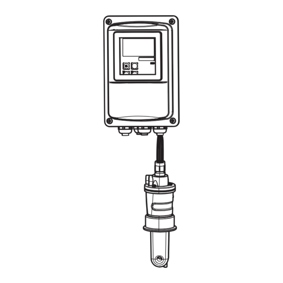
Page 4: Installation Of The Compact Version Or Cls54 Sensor For Separate Version
Install the compact version or the CLS54 sensor directly on the pipe or vessel socket via the process connection (depending on ordered version). When installing the Smartec S CLD134 or the sensor, make sure that the flow opening of the sensor is oriented in the flow direction of the medium. An orientation arrow on the sensor facilitates orientation. -
Page 5: Connection Diagram
15 V 10-50 V – – 10-50 V a0004895 Fig. 3: Electrical connection of Smartec S CLD134 Signal output 1 conductivity Conductivity sensor Signal output 2 temperature Temperature sensor Auxiliary power output Alarm (contact position: no current) Binary input 2 (MRS 1+2) -
Page 6: Structure And Termination Of Measuring Cable
Wiring Smartec S CLD134 Connection of binary inputs 15 V a0005639 Fig. 4: Connection of binary inputs when using external contacts Auxiliary power output Contact inputs D1 and D2 External contacts, not energized External contacts, not energized Structure and termination of measuring cable... -
Page 7: Commissioning
Smartec S CLD134 Commissioning Commissioning Function check Warning! • Check all connections for correctness. • Make sure that the supply voltage is identical to the voltage indicated on the nameplate! Key assignment Assignment Use the CAL key to acknowledge calibration data and to continue through the calibration process. -
Page 8: Quick Setup
Commissioning Smartec S CLD134 Quick setup After switching the transmitter on, configure the major functions required for accurate measurement. The following section gives you an example for a basic configuration. Input Selection or range Display (factory setting bold) Press the ENTER key. - Page 9 Smartec S CLD134 Commissioning Input Selection or range Display (factory setting bold) 15. If you are working in applications that fluctuate a great deal and you need to stabilize the display, enter the required damping factor in A7. 1 ... 60 Damping Confirm your entry by pressing ENTER.
-
Page 10: Calibration
Commissioning Smartec S CLD134 Note! You must perform an air set before installing the sensor. To do so, refer to the chapter "Calibration". Calibration To access the "Calibration" function group, press the CAL key (code = 22). Code Field Selection or range... - Page 11 Smartec S CLD134 Commissioning Code Field Selection or range Display Info Calculated cell 6.300 1/cm The calculated cell constant is displayed C124 0.1 ... 6.3 ... 9.99 cm constant is displayed Cellconst and entered in A5. If the calibration status is not o.k., the Calibration status is o.k.
- Page 12 www.endress.com/worldwide KA401C/07/en/07.07 Printed in Germany / FM+SGML 6.0 71059831...