Table of Contents
Advertisement
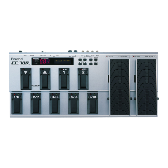
Owner's Manual
201a
Before using this unit, carefully read the sections entitled: "USING THE UNIT SAFELY" (p. 2)
and "IMPORTANT NOTES" (p. 4). These sections provide important information concerning
the proper operation of the unit. Additionally, in order to feel assured that you have gained a
good grasp of every feature provided by your new unit, Owner's Manual should be read in its
entirety. The manual should be saved and kept on hand as a convenient reference.
202
Copyright © 2007 ROLAND CORPORATION
All rights reserved. No part of this publication may be reproduced in any form without the
written permission of ROLAND CORPORATION.
Advertisement
Table of Contents

Related Manuals for Roland FC-300


Summary of Contents for Roland FC-300
- Page 1 Owner’s Manual should be read in its entirety. The manual should be saved and kept on hand as a convenient reference. Copyright © 2007 ROLAND CORPORATION All rights reserved. No part of this publication may be reproduced in any form without the...
- Page 2 Refer all servicing to your retailer, the nearest Roland Service Center, or an authorized Roland distributor, as listed on the “Information” page. • Never use or store the unit in places that are: •...
- Page 3 101b • The unit and the AC adaptor should be located so their location or position does not interfere with their proper venti- lation. 102d • Always grasp only the output plug or the body of the AC adaptor when plugging into, or unplugging from, this unit or an outlet.
-
Page 4: Important Notes
Roland assumes no liability concerning such loss of data. Additional Precautions • Please be aware that the contents of memory can be irretrievably lost as a result of a malfunction, or the improper operation of the unit. -
Page 5: Table Of Contents
Turning the Power On and Off ... 13 When Using the FC-300 as a MIDI Foot Controller ... 13 When Using the FC-300 as a Dedicated Foot Controller for an RRC2 IN Device (e.g., the VG-99) ... 13 About the MODES... 14 Standard Mode (p. - Page 6 Transmitted Messages ... 62 3. Exclusive Communications... 64 4. Parameter Address Map (Model ID = 00H 00H 20H)... 64 Specifications...68 FC-300 : MIDI FOOT CONTROLLER ... 68 Index...69 ] Pedals to Make the Settings ... 48 ] Pedal Step Size ... 49...
-
Page 7: Introduction
Introduction Main Features • Features four modes (Standard Mode, Control Change Mode, System Exclusive Mode, Patch Mode) • Unit comes equipped with two expression pedals and two control pedals. You can also expand control even further with up to three external expression pedals or six external control pedals. -
Page 8: Top Panel (Buttons)
MIDI messages and blank spaces. MODE button / DEL (delete) button Press this to change the FC-300’s operating mode. In the Edit screen, this is used to delete a MIDI message or a character at the cursor location. VALUE button [ Use this when changing the values of settings. -
Page 9: Top Panel (Pedals)
Top Panel (Pedals) ] (down / up) pedals Use these pedals to switch banks and select numbers. Additionally, you can switch modes by pressing the pedals simultaneously. CTL (Control) pedals (1, 2) You can assign the desired functions to these pedals, then use them for control over those functions. -
Page 10: Rear Panel
You can connect an external RRC2 IN device here to transmit and receive performance data between the devices. At the same time, the FC-300 can be powered by the external RRC2 IN device. POWER switch Turns the power on and off. -
Page 11: Making The Connections
When using the FS-5U or FS-6, set the polarity switch as shown below. fig.FS-5U.eps BOSS FS-5U Install batteries The FC-300 is not loaded with batteries when purchased. When running the FC-300 on battery power, install the batteries using the following figure. fig.change-battery.eps Connect to footswitch jack External Sound Module Guitar Amp etc. -
Page 12: Connections To Make When Using The Fc-300 As A Dedicated Foot Controller For An Rrc2 In Device (E.g., The Vg-99)
If you’re using a BOSS PSA series AC adaptor, here’s how to connect the cord and secure it on the cord hook. fig.CordHook.j.eps Connections To Make When Using the FC-300 as a Dedicated Foot Controller for an RRC2 IN Device (e.g., the VG-99) fig. -
Page 13: Turning The Power On And Off
Then set the power switch on the FC-300 to “ON.” fig. When the power is turned on, the FC-300 starts up in Standard Mode. Turning Off the Power Switch off the power to the device connected to the FC-300. -
Page 14: About The Modes
Introduction About the MODES The FC-300 features the following four modes. The pedals function differently depending on the mode that’s selected. This manual describes each mode separately, while explaining the items available in a particular mode. Standard Mode (p. 16) This mode is for sending Program Change messages and Control Change messages. -
Page 15: Switching Modes
Switching Modes You can switch modes using one of the following methods. • Press [MODE] • Press a footswitch (BOSS FS-5U/FS-6; sold separately) connected to the MODE jack • Simultaneously press the [ fig. Standard Mode Control Change Mode System Exclusive Mode Patch Mode About the Mode Indicators Standard Mode... -
Page 16: Standard Mode
001–128 129–130 Setting How Tones are Switched You can set the way the FC-300 switches tones with the pedals and displays tone numbers. Make the settings to match the specifications of the external MIDI devices you are using (p. 47). -
Page 17: Transmitting Control Change Messages
Transmitting Control Change Messages You can transmit Control Change messages with expression pedals and control pedals. Using the Expression Pedals In keeping with the movement of the expression pedal, Control Change messages with the controller numbers set for each pedal are transmitted consecutively. Each pedal is set at the factory as shown below. -
Page 18: Using The External Control Pedals And Expression Pedals
Assigned to CTL Pedal: These function in the same way as the FC-300’s built-in control pedals. Connect a control pedal to the EXP PEDAL/CTL jack and set the FC-300 to enable use of the pedal. (p. 50) * If you have two FS-5U pedals or an FS-6 pedal connected to the CTL3,4 jack with a special PCS-31 connecting cable (from Roland;... -
Page 19: Change The Pedal Settings
Change the Pedal Settings You can freely change the settings for each pedal. In the Standard Mode’s top screen, press PARAMETER [ Press PARAMETER [ Press VALUE [ ] to change the value. MIDI Messages This selects the MIDI messages to be transmitted. fig.05-009 MIDI Message •... - Page 20 When the pedal is ON Guitar Amp (amps channel switching jack) When you have finished making the settings, press [EXIT] to return to the initial screen. The settings are saved, and the FC-300 returns to the initial screen. Closed FC-300 (AMP CONTROL jack) Open...
-
Page 21: Control Change Mode
Pedal Setting Number You can also store up to five sets, or configurations, of settings for all of the pedals within the FC-300’s memory. Called pedal settings, these configurations can be switched as needed (p. 26). Transmitting Control Change Messages Pressing the various pedals transmits the Control Change messages set for the respective pedal over the selected MIDI channel. -
Page 22: Using The Expression Pedals
Control Change Mode Using the Expression Pedals In keeping with the movement of the expression pedal, Control Change messages with the controller numbers set for each pedal are transmitted consecutively. Each pedal is set at the factory as shown below. Expression Pedal EXP PEDAL 1 EXP PEDAL 2... -
Page 23: Using Additional Footswitches And Expression Pedals
Assigned to CTL Pedal: These function in the same way as the FC-300’s built-in control pedals. Connect a control pedal to the EXP PEDAL/CTL jack and set the FC-300 to enable use of the pedal. (p. 50) * If you have two FS-5U pedals or an FS-6 pedal connected to the CTL3,4 jack with a special PCS-31 connecting cable (from Roland;... -
Page 24: Change The Pedal Settings
Control Change Mode Change the Pedal Settings You can freely change the settings for each pedal. In the Control Change Mode’s top screen, press PARAMETER [ Pressing PARAMETER [ Press VALUE [ MIDI Messages This selects the MIDI messages to be transmitted. fig.05-009 MIDI Message •... - Page 25 When you have finished with the editing, press [EXIT]. The top screen appears. After making the changes, follow the instructions in “Storing Controller Numbers Assigned to the Pedals (Pedal Settings)” (p. 26) to save the settings. Closed FC-300 (AMP CONTROL jack) Open FC-300 (AMP CONTROL jack)
-
Page 26: Storing Controller Numbers Assigned To The Pedals (Pedal Settings)
Storing Controller Numbers Assigned to the Pedals (Pedal Settings) The FC-300 can store up to five different configurations of settings made for all of the pedals (“Change the Pedal Settings” (p. 24)) in Control Change mode. These configurations are called pedal settings, and you can switch them as needed. -
Page 27: Deleting A Pedal Setting
Deleting a Pedal Setting Press [WRITE] in the top screen of the Control Change Mode. Pressing PARAMETER [ Select the number (1–5) for the pedal settings you want to delete with VALUE The erased pedal setting Press [WRITE]. “Sure?” appears in the display. If you want to delete the setting, press [WRITE];... -
Page 28: System Exclusive Mode
System Exclusive Mode This mode is for transmitting and receiving System Exclusive messages. Pressing the FC-300’s pedals and pedals connected to the EXP PEDAL/CTL jacks transmits the pedal status via System Exclusive messages. In addition, display content and pedal indicators can be switched with System Exclusive messages received by the FC-300. -
Page 29: Patch Mode
About the Patch A “patch” is a group of multiple MIDI messages (MIDI stream) and other settings that are configured together as a single unit. The FC-300 can store up to 100 individual patches.(p. 44) The patch can set the following parameters. -
Page 30: Transmitting Control Change Messages
Using the Control Pedals and Expression Pedal Switches You can connect separately available footswitches and expression pedals and use the external pedals just like the FC-300’s pedals to transmit MIDI messages. Each pedal is set at the factory as shown below. Pedal... -
Page 31: Using The External Control Pedals And Expression Pedals
Assigned to CTL Pedal: These function in the same way as the FC-300’s built-in control pedals. Connect a control pedal to the EXP PEDAL/CTL jack and set the FC-300 to enable use of the pedal. (p. 50) * If you have two FS-5U pedals or an FS-6 pedal connected to the CTL3,4 jack with a special PCS-31 connecting cable (from Roland;... -
Page 32: Transmitting Patch Data
] and [ ] pedals, read “Using the [ Pedals to Make the Settings” (p. 48). You can program the FC-300 so that pressing the [ ] and ] pedals changes patch numbers ten at a time. For details, refer to “Setting the ] Pedal Step Size”... -
Page 33: Creating Patches
Creating Patches In the Patch Mode’s top screen, when press PARAMETER [ setting screens appear in the display. Press PARAMETER [ parameter you want to change. The patch can set the following parameters. • Patch’s ON Stream • Patch’s OFF Stream •... -
Page 34: Editing Midi Streams
Patch Mode Editing MIDI Streams In the Patch Mode’s top screen, press PARAMETER [ Use the PARAMETER [ want to edit, then press [WRITE]. “Edit MIDI” appears in the screen; press [WRITE]. The screen for selecting the MIDI stream editing function appears. The following display appears when the message is not assigned. - Page 35 When Setting Channel Messages and Realtime Messages Press PARAMETER [ MIDI Message MIDI Channel Message Number Data Press VALUE [ ] to select the MIDI message to be edited. MIDI Message Data MIDI Channel (CH#), Program Number (PC#) MIDI Channel (CH#), Controller Number (CC#), Value (VAL) N.ON MIDI Channel (CH#), Note Number (NOTE#), Velocity (V) N.OFF...
- Page 36 ] to move the cursor to the The maximum amount of data that can be saved to a system exclusive message is 256 bytes. With Roland System Exclusive messages, moving the cursor to the message in front of F7 (the end of the transmitted...
- Page 37 When Setting System Exclusive Messages Using the Template When assigning the following System Exclusive messages, use the template. Template GM SYS ON GM SYS OFF V-LINK ON V-LINK OFF MMC STOP Press PARAMETER [ MIDI Message MIDI Channel Message Number Data Press VALUE [ ] to select the “SYSEX.”...
- Page 38 Patch Mode Copying and Moving MIDI Messages Within a Stream You can copy MIDI messages saved within a MIDI stream. Use this function when you want to program a number of similar messages in a stream. Messages in MIDI streams are output in the same order they are programmed. To change the sequence of the messages in a stream, use the Move function.
-
Page 39: How To Copy Midi Streams
How to Copy MIDI Streams You can copy an edited stream to a different patch or different stream. In the Patch Mode’s top screen, press PARAMETER [ Press PARAMETER [ source, then press [WRITE]. Press PARAMETER [ Press VALUE [ ] to select the stream to be used as the copy source, then press [WRITE]. -
Page 40: How To Delete Midi Streams
Patch Mode How to Delete MIDI Streams You can delete content in streams. In the Patch Mode’s top screen, press PARAMETER [ Press PARAMETER [ delete data, then press [WRITE]. Press PARAMETER [ “Sure?” appears in the display; press [WRITE] once more. After making the changes, follow the instructions in “Storing (Saving) Patches”... -
Page 41: Setting The Amp Control
After making the changes, follow the instructions in “Storing (Saving) Patches” (p. 44) to save the setting to a patch. ] to select “AMP Ctl.” ] to select “1” or “2” of the AMP Ctl. Closed FC-300 (AMP CONTROL jack) Open FC-300 (AMP CONTROL jack) -
Page 42: Change The Pedal Settings
You can assign these in the same manner as streams set as patch parameters. (p. 34) However, the timing for transmission of OFF streams follows the settings made in Pedal mode. You can set ON streams and OFF streams only with the FC-300’s CTL pedals. - Page 43 When the pedal is OFF Guitar Amp (amps channel switching jack) When the pedal is ON Guitar Amp (amps channel switching jack) Closed FC-300 (AMP CONTROL jack) Open FC-300 (AMP CONTROL jack) Patch Mode The Range parameter is enabled only when CC#, P.BEND, or CH.PRS is...
-
Page 44: Set The Patch Name
Press VALUE [ press [WRITE]. “Sure?” appears in the display; press [WRITE] once more. The set value is saved, and the FC-300 returns to the top screen. ] to select “Patch Name.” ] to move the cursor, and press VALUE [... -
Page 45: Deleting Patches
Select the patch you want to delete in the Patch mode’s top screen, then press [WRITE]. Press PARAMETER [ ] to select “Delete.” Press [WRITE]. “Sure?” appears in the display; press [WRITE] once more. The selected patch is deleted, and the FC-300 returns to the top screen. Patch Mode... -
Page 46: Other Features
When you’ve finished making the settings, press [UTILITY] or [EXIT]. The data is saved, and FC-300 returns to the top screen. Adjusting the LCD Contrast Depending on where the FC-300 is placed, the display (on the right) may become difficult to read. If this occurs, adjust the display contrast. -
Page 47: Setting The Method Used For Transmitting Program Change Messages In Standard Mode (Pc Mode)
701–800 801–900 901–990 When set to “SOUND MODULE,” the FC-300’s LCD appears bank select MSB and LSB, and the transmitted bank select message with program change message. Program Change Number When you’ve finished making the settings, press [UTILITY] or [EXIT]. -
Page 48: Using The [ ] [ ] Pedals To Make The Settings
Other Features Using the [ ] Pedals to Make the Settings Press PARAMETER [ Press the VALUE [ Here are some examples of operation in Standard Mode. Value Explanation IMMEDIATE Program changes are transmitted immediately when [ Example) When starting from “003,” pressing [ neously transmits PC#8. -
Page 49: Setting The [ ] [ ] Pedal Step Size
Setting the [ You can set the size of the step made when the [ Press PARAMETER [ Press VALUE [ ] to make the setting. Value Explanation 5STEP The number decreases or increases by five each time [ pressed. 10STEP The number decreases or increases by ten each time [ pressed. -
Page 50: Setting The Polarity Of The Amp Control Jacks
Setting the Polarity of the AMP CONTROL Jacks Change this parameter if the indicator on an amp connected to an AMP CONTROL jack (1 or 2) does not correspond to the ON indicator (indicator lit) on the FC-300. Press PARAMETER [ “SYS:AMP 2 Pol.”... -
Page 51: Switching The Function Of The Mode Pedal Jack
Switching the Function of the MODE Pedal Jack This sets the modes that can be selected when the mode is switched with a pedal. This setting allows you to toggle only between the modes you need when using the pedal. Press PARAMETER [ Standard Mode Control Change... -
Page 52: Setting The Midi Transmit Channel
Other Features Setting the MIDI Transmit Channel This sets the Transmit Channel of the MIDI messages. Press PARAMETER [ Press VALUE [ ] to set the transmit channel. When you’ve finished making the settings, press [UTILITY] or [EXIT]. Setting the Device ID This sets the Device ID used for transmitting and receiving system exclusive messages. -
Page 53: Setting The Bank Select Value
When you’ve finished making the settings, press [UTILITY] or [EXIT]. Transmitting Data to an External MIDI Device (Bulk Dump) On the FC-300, you can use System Exclusive messages to provide another FC-300 with identical settings, and save settings on a MIDI sequencer or other device. -
Page 54: Receiving Data From An External Midi Device (Bulk Load)
Press [WRITE]. The “Now Sending...” message appears in the display when the FC-300 sends the data. The top screen appears in the display when the FC-300 finishes sending the data. If either ALL, CONTROL, or PATCH is selected in Step 2, the message “Erase Tmp Data Sure?”... -
Page 55: Appendices
Appendices Restoring the Factory Settings (Factory Reset) You can restore all of the FC-300’s settings to their original factory settings. This is referred to as “Factory Reset.” Use the following procedure when carrying out Factory Reset. Switch off the power. -
Page 56: Adjusting The Expression Pedal
Appendices Adjusting the Expression Pedal Although the FC-300’s EXP pedals are adjusted for optimal performance when shipped from the factory, extended use over time and under certain usage conditions may result in the pedals going out of adjustment. If you find the pedals exhibiting problems, such as “a failure to completely shut off the volume when used... -
Page 57: Error Messages
[Solution 1] Delete any unnecessary patches. (p. 45) [Cause 2] The area of memory for the FC-300’s internal operations became full while the patch was being edited (COPY, INS, etc). [Solution 2] Delete MIDI messages within the patch. (p. 40) -
Page 58: Troubleshooting
Pressing a number pedal and selecting the number transmits the message. • When you send messages from the FC-300, make sure the FC-300 is set to the settings appropriate for sending data. Check the “Setting the Method Used for Transmitting Program Change messages in Standard Mode (PC Mode)”... -
Page 59: Midi Implementation
MIDI FOOT CONTROLLER Model FC-300 Roland System Exclusive Messages 1. Data Format for Exclusive Messages Roland’s MIDI implementation uses the following data format for all Exclusive messages (type IV): Byte Description System Exclusive Status Manufacturer ID (Roland) Device ID Model ID... -
Page 60: One-Way Transfer Procedure
• The error-checking process uses a checksum that provides a bit pattern where the last 7 bits are zero when values for an Command ID RQ1 (11H) DT1 (12H) Description System Exclusive Status Manufacturer ID (Roland) Device ID Model ID Command ID Address MSB Address LSB Size MSB... - Page 61 Exclusive one. This fact is inconvenient for devices that support a “soft-thru” function. To maintain compatibility with such devices, Roland has limited the DT1 to 256 bytes so that an excessively long message is sent out in separate ‘segments.’...
-
Page 62: Recognized Receive Data
When FC-300 receives Active Sensing, it measures time intervals between incoming messages. If the subsequent message will not come within 400 msec after the previous one, FC-300 turns off Active Sensing for a period and stops measuring message intervals. System Exclusive Message... - Page 63 Messages” (p. 59) and “3. Exclusive Communications” (p. 64). MIDI Machine Control (MMC) Status Byte Third * FC-300 can set the following MMC commands. * Does not transmit while in System Exclusive Mode. MIDI Implementation Data Status iiH, ddH, ..., eeH...
-
Page 64: Exclusive Communications
EOX (End of System Exclusive) 4. Parameter Address Map (Model ID = 00H 00H 20H) There are two type of the FC-300 System Exclusive message. FC-300 can send and receive the operation of this unit and display information by using the system exclusive message. - Page 65 Pedal Status (Individual area) Address (H) Size (H) Data (H) Parameter 20 00 00 01 00/7F Pedal 1/6 Status 20 01 00 01 00/7F Pedal 2/7 Status 20 02 00 01 00/7F Pedal 3/8 Status 20 03 00 01 00/7F Pedal 4/9 Status 20 04 00 01...
- Page 66 MIDI Implementation Controller Status (Individual area) Address (H) Size (H) Data (H) Parameter 50 00 00 01 00/7F AMP CON- TROL 1 Status 50 01 00 01 00/7F AMP CON- TROL 2 Status • Receives Data Set (DT1) in all mode. •...
- Page 67 MIDI FOOT CONTROLLER Model FC-300 Function... Basic Default 1–16 Channel Changed 1–16 Default Messages Mode Altered ************** Note 0–127 Number True Voice ************** Velocity Note ON o 9n v=1–127 Note OFF o 8n v=0–127 o 0–127 After Key's o 1–16...
-
Page 68: Specifications
Options AC Adaptor: BOSS PSA series Footswitch: BOSS FS-5U, FS-6 Expression Pedal: Roland EV-5, BOSS FV-500L, FV-500H * In the interest of product development, the specifications and/or appearance of this unit are subject to change without prior notice. ] pedals... -
Page 69: Index
Index Numerics 1/6 – 5/10 pedals ... 9 1/6–5/10 ... 21 AMP 1 Pol..50 AMP 2 Pol..50 AMP CONTROL 1, 2 jack ... 10 AMP CTL OP ... 20, 43 AMP Ctl Op ... 25 Assign Number ... 42 Bank Display ... - Page 70 Index System Exclusive Messages ... 59 System Exclusive Mode ... 14 System Parameters ... 46 Threshold ... 56 Troubleshooting ... 58 Tx Channel ... 52 UTILITY button ... 8 VALUE button ... 8 WRITE button ... 8...
- Page 71 IMPORTANT: THE WIRES IN THIS MAINS LEAD ARE COLOURED IN ACCORDANCE WITH THE FOLLOWING CODE. BLUE: NEUTRAL BROWN: LIVE As the colours of the wires in the mains lead of this apparatus may not correspond with the coloured markings identifying the terminals in your plug, proceed as follows: The wire which is coloured BLUE must be connected to the terminal which is marked with the letter N or coloured BLACK.
- Page 72 Information When you need repair service, call your nearest Roland Service Center or authorized Roland distributor in your country as shown below. AFRICA PHILIPPINES G.A. Yupangco & Co. Inc. 339 Gil J. Puyat Avenue EGYPT Makati, Metro Manila 1200, Al Fanny Trading Office...