Endress+Hauser SS2100 Operating Instruction
H2s tdlas gas analyzer
Hide thumbs
Also See for SS2100:
- Operating instructions manual (128 pages) ,
- Operator's manual (114 pages) ,
- Safety manual (37 pages)

Related Manuals for Endress+Hauser SS2100


Summary of Contents for Endress+Hauser SS2100
- Page 1 Products Solutions Services BA02191C/66/EN/01.21 Operating Instruction SS2100 H S TDLAS Gas Analyzer Class I, Division 2 Group A, B, C, D T3 / T3C Class I, Zone 2 IIC T3 / T3C Type 4X, IP66...
- Page 2 SS2000e, SS2000XP, SS3000, SS3000e Copyright © 2021 Endress+Hauser, Inc. No part of this manual may be reproduced in whole or in part without the express written permission of Endress+Hauser, Inc. Endress+Hauser reserves the right to change product design and specifications at any...
-
Page 3: Table Of Contents
Shutting Down the SCS ......... 4-7 Heat trace bundle sleeve (optional)....... . 4-11 Endress+Hauser... - Page 4 SS2100 H S TDLAS Gas Analyzer BA02163C Appendix A: Specifications Spare Parts ..........A-12 Appendix B: Maintenance and Troubleshooting Gas Leaks .
-
Page 5: Who Should Read This Manual
Pay close attention to this information. General Warnings and Cautions Instructional icons are provided in this manual and on the SS2100 unit to alert the user of potential hazards, important information and valuable tips. Following are the symbols and associated warning and caution types to observe when servicing the analyzer. -
Page 6: Safety Warning Label
Any work in a hazardous area must be carefully controlled to avoid creating any possible ignition sources (e.g., heat, arcing, sparking, etc.). Toxins. Endress+Hauser analyzers measure a variety of gases, including high-level H S. Follow all safety protocols governing toxic gases and potential leaks. -
Page 7: Equipment Labels
BA02191C SS2100 TDLAS H S Gas Analyzer Equipment labels Warning statement for hazardous voltage. Contact may cause electric shock or burn. Turn off and lock out system before servicing. Failure to follow all directions may result in damage or malfunction of the analyzer. -
Page 8: Instructional Symbols
United States www.endress.com About the Gas Analyzers The SS2100 includes tunable diode laser (TDL) absorption spectrometers operating in the near- to short-wavelength infrared. Each compact sensor consists of a TDL light source, sample cell and detector specifically configured to enable high sensitivity measurement of a particular component within the presences of other gas phase constituents in the stream. -
Page 9: Sample Conditioning System
The laser beam enters the cell and reflects off the mirror(s) making multiple passes through the sample gas and eventually exiting the cell where the remaining beam intensity is measured by a detector. With the SS2100, sample gas flows continuously through the sample cell ensuring that the sample is always representative of the flow in the main pipe. - Page 10 SS2100 TDLAS H S Gas Analyzer BA02191C OPTICAL HEAD DETECTOR LASER WINDOW INLET PRESSURE SENSOR FAR MIRROR OUTLET Figure 1–1 Schematic of a typical laser diode absorption spectrometer Figure 1–2 shows the typical raw data (in arbitrary units [u.a.]) from a laser absorption spectrometer scan including the incident laser intensity, I (), and...
- Page 11 BA02191C SS2100 TDLAS H S Gas Analyzer Incident Energy I Raw Signal, I (l) Raw Signal, I (l) (Contaminated Wavelength [a.u.] Figure 1–2 Typical raw signal from a laser diode absorption spectrometer with and without mirror contamination 0.99 0.98 0.97 0.96...
-
Page 12: Differential Tdlas
Wavelength modulation spectroscopy (WMS) signal detection Endress+Hauser takes the fundamental absorption spectroscopy concept a step further by using a sophisticated signal detection technique called wavelength modulation spectroscopy (WMS). When employing WMS, the laser drive current is modulated with a kHz sine wave as the laser is rapidly tuned. -
Page 13: Getting Familiar With The Gas Analyzer
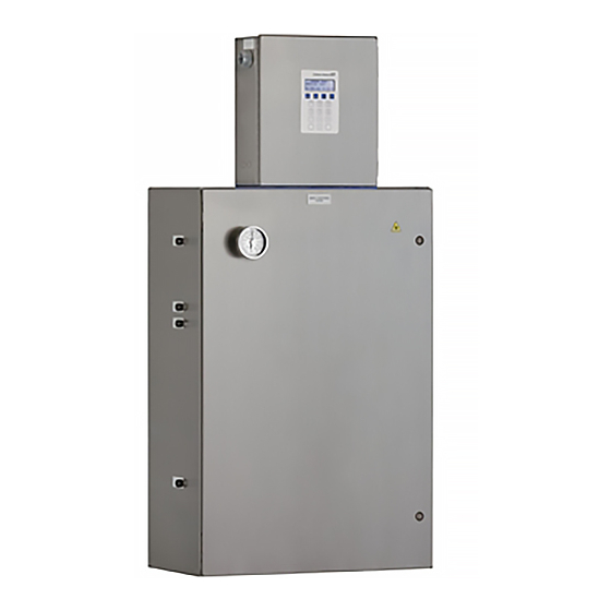
Getting Familiar with the Gas Analyzer Figure 1–5 on page 1–9 shows a sample SS2100 H S analyzer from a front view. The analyzer is typically comprised of two main enclosures; the analyzer electronics and the Sample Conditioning System (SCS). - Page 14 SS2100 TDLAS H S Gas Analyzer BA02191C Power is connected to the analyzer from a 120 VAC, 240 VAC or 24Vdc power source. The sample supply/return and instrument air are connected on the opposite side of the enclosure. Inside the analyzer electronics enclosure is the electronics assembly, as shown in Figure 1–6 on page 1–11 and Figure 1–7 on page 1–12.
- Page 15 BA02191C SS2100 TDLAS H S Gas Analyzer RELAY DRIVER AND TERMINAL BLOCK TB2, 4-20 mA CONTROL OUTPUT SIGNALS BOARD STACK HYTEK TEMPERATURE CONTROLLER POWER SUPPLY BACKPLANE ARM9 CONTROL BOARD STACK COMPONENT GROUND PROTECTIVE GROUND FUSES (F2. F1) ALARM/ SIGNAL RELAYS...
- Page 16 SS2100 TDLAS H S Gas Analyzer BA02191C TERMINAL BLOCK TB2, RELAY DRIVER AND 4-20 mA OUTPUT SIGNALS CONTROL BOARD STACK POWER SUPPLY HYTEK TEMPERATURE CONTOLLER BACKPLANE FUSE (F2) ARM9 CONTROL COMPONENT BOARD STACK GROUND PROTECTIVE GROUND FUSE (F1) ALARM/ SIGNAL...
-
Page 17: Potential Risks Affecting Personnel
S levels of the SCS enclosure using the port from the safety purge kit to ensure the purge has cleared any toxic gas. 3. If no gas leak is detected, open the SCS enclosure door. Follow all safety protocols governing toxic gases and potential leaks. Endress+Hauser... -
Page 18: Explosion Hazard
SS2100 H S TDLAS Gas Analyzer BA02191C Electrocution hazard 1. Shut off power at the main disconnect external to the analyzer. Complete this action before performing any service that requires working near the main input power or disconnecting any wiring or other electrical components. -
Page 19: What Should Be Included In The Shipping Box
3 - I NSTALLATION This chapter describes the processes used to mount and install your SS2100 S analyzer. Once the system arrives, you should take a few minutes to examine the contents before installing the unit. Endress+Hauser Class 1 Division II analyzers use a non-incendive protection method, and as such all portions of the local installation codes apply. -
Page 20: Installing The Analyzer
Mounting hardware (e.g., spring nuts, 3/8 in. x 1-1/2 in. machine screws and nuts) Bolts or screws used for wall-mounting the SS2100 must be able to support four times the weight of the instrument (approximately 59 Kg [130 lbs] with sample system). -
Page 21: Mounting The Analyzer
Refer to “Lifting/carrying the analyzer” on page 3-3. Endress+Hauser analyzers are designed for operation within the specified ambient temperature range. Intense sun exposure in some areas may cause the analyzer temperature to exceed the maximum. -
Page 22: Connecting Electrical Power To The Analyzer
Once all screws are tightened, the analyzer should be very secure and ready for the electrical connections. Connecting Electrical Power to the Analyzer Depending on your configuration, your SS2100 H S analyzer system will be set up for either 120 VAC or 240 VAC at 50/60 Hz single-phase input, or optionally 24 VDC input. -
Page 23: Protective Chassis And Ground Connections
BA02191C SS2100 TDLAS H S Gas Analyzer Hazardous voltage and risk of electric shock. Turn off and lock out system power before opening the electronics enclosure and making any connections. Interconnection of the analyzer enclosure and cell enclosure shall be accomplished using wiring methods approved for Class 1,... - Page 24 SS2100 TDLAS H S Gas Analyzer BA02191C Refer to Figure 1–5 on page 1–9, Figure 1–6 on page 1–11 and Figure 1–7 on page 1–12 for the protective and chassis ground locations. To connect electrical power to the H S analyzer 1.
- Page 25 BA02191C SS2100 TDLAS H S Gas Analyzer AC (HOT/LINE 1) NEUTRAL Figure 3–2 AC single phase (120 VAC or 240 VAC) connection terminal block in analyzer electronics enclosure For DC systems, connect the minus wire to the terminal marked “-,” and the positive wire to the terminal marked “+,” as shown in Figure 3–3 on page 3–7.
-
Page 26: Field Interface Loads (Solenoid Valves)
SS2100 TDLAS H S Gas Analyzer BA02191C Field interface loads (solenoid valves) The SS2100 H S analyzer must be connected to a certified solenoid having a temperature code of T4, T5, or T6 at a maximum ambient temperature of ... - Page 27 BA02191C SS2100 TDLAS H S Gas Analyzer TERMINAL 4 LINE TERMINAL 6 TERMINAL 5 Figure 3–4 AC connection terminal block for 120 VAC enclosure heater 5. Strip back the jacket and/or insulation of the wires just enough to connect to the power terminal block.
-
Page 28: Connecting The Output Signals And Alarms
SS2100 TDLAS H S Gas Analyzer BA02191C 1. Holding the fitting piece at one end, generously apply the STL8 lubricant on the male threaded surface (at least five threads wide) as shown below. Figure 3–5 Applying conduit lubricant 2. Screw the female pipe thread onto the male fitting until the lubricated threads are engaged. - Page 29 BA02191C SS2100 TDLAS H S Gas Analyzer Description of Device Parameters for your analyzer to change the Assignable Alarm configuration. The Assignable Alarm output can be wired for OPEN or CLOSED depending on which terminals are used normally open (NO) or normally closed (NC).
- Page 30 SS2100 TDLAS H S Gas Analyzer BA02191C 3. Pull the customer-supplied cables for the current loop, alarms, digital input, Ethernet and the serial cable through the conduit into the H S analyzer electronics enclosure. (No connections are required for the analyzer to run and function properly. Only make connections for signals that will be used for communication with the analyzer).
-
Page 31: Changing The 4-20 Ma Current Loop Mode
BA02191C SS2100 TDLAS H S Gas Analyzer Table 3–1 H S analyzer input/output signal connections Terminal Description D-Conn Color Serial RX Pin-3 Black Serial TX Pin-2 COM Serial Ground Pin-5 Shield Current Loop +(1) Current Loop - (1) Current Loop + (2) - Page 32 SS2100 TDLAS H S Gas Analyzer BA02191C To change the 4-20 mA board from source to sink 1. Disconnect power from the analyzer and open the electronics enclosure cover. Take care not to disturb the electrical assembly inside. 2. Locate the relay control board in the upper right of the electronics enclosure, as shown in Figure 1–6 on page 1–11 or Figure 1–7 on...
-
Page 33: Connecting The Gas Lines
BA02191C SS2100 TDLAS H S Gas Analyzer 3. Continue pressing the * key until the 4-20 mA Test parameter displays. <SET PARAMETER MODE> AO 4-20 mA Test 0.00000 Enter a value (%) 4. Enter the desired percentage of full scale and press *. -
Page 34: Instrument Air
SS2100 TDLAS H S Gas Analyzer BA02191C Process samples may contain hazardous material in potentially flammable and/or toxic concentrations. Personnel should have a thorough knowledge and understanding of the physical properties and safety precautions for the sample contents before installing the SCS. - Page 35 BA02191C SS2100 TDLAS H S Gas Analyzer 2. Also, confirm that the field pressure reducing station is installed properly at the sample probe and that the pressure regulator at the field pressure reducing station is closed (adjustment knob turned fully counterclockwise).
-
Page 36: Conditioning The Scs Tubing
Heat Trace Bundle Sleeve (Optional) The Heat Trace Bundle Sleeve, manufactured by others, is an option for the Endress+Hauser analyzer. Refer to Figure A–9 on page A–11. 3-18 Endress+Hauser... -
Page 37: Tools
SCS enclosure per site requirements. Heated line seal installation The heat-shrinkable entry seal Model NUS-4X supplied by Endress+Hauser provides a waterproof fitting where the heat trace bundle enters the sample conditioning system (SCS) enclosure. This seal consists of a three-part assembly;... - Page 38 SS2100 TDLAS H S Gas Analyzer BA02191C THIS PAGE INTENTIONALLY LEFT BLANK 3-20 Endress+Hauser...
-
Page 39: 4: Sample Conditioning System
SCS. About the SCS Endress+Hauser sample conditioning systems are designed to filter incoming gas, as well as control pressure and flow to the analyzer. The SCS uses a 7 micron particulate filter and a membrane separator that removes entrained liquids or particles from the natural gas stream before they enter the analyzer. -
Page 40: Checking The Scs Installation
An optional sample probe and/or field pressure reducing station may be provided by Endress+Hauser or through a third party. This is not included in a standard configuration. Endress+Hauser... - Page 41 BA02191C SS2100 H S TDLAS Gas Analyzer 3. Confirm that the relief valve at the field pressure reducing station has been set to the specified setpoint. The relief valve is located on the pressure reducing regulator at the process sample tap.
-
Page 42: Starting Up The Scs
SS2100 H S TDLAS Gas Analyzer BA02191C Starting up the SCS After the SCS installation has been thoroughly checked, you are ready to begin preparing for initial SCS startup. To prepare for SCS startup 1. Confirm that all AC power switches for the analyzer and SCS are off. - Page 43 To start up the field pressure reducing station An optional field pressure reducing station and/or sample probe may be provided by Endress+Hauser or through a third party. This is not included in a standard configuration. The process sample at the sample tap may be at a high pressure.
- Page 44 SS2100 H S TDLAS Gas Analyzer BA02191C 3. Open the bypass flow meter metering valve to establish sample flow from the sample probe and set the metering valve to the specified value. Do not open the cell flow meter at this point.
-
Page 45: Shutting Down The Scs
BA02191C SS2100 H S TDLAS Gas Analyzer 5. Confirm the sample flow and pressure setpoints and readjust the metering valves and pressure regulator at the field pressure reducing station to the specified setpoints, if necessary. 6. Confirm the sample bypass flow and readjust the bypass metering valve to the specified setpoint, if necessary. - Page 46 SS2100 H S TDLAS Gas Analyzer BA02191C Due to the high pressure of the process sample, it is advisable to allow the sample bypass flow to continue during short-term isolation of the analyzer. Continuing sample bypass flow allows the field pressure regulator to continue normal operation without...
- Page 47 BA02191C SS2100 H S TDLAS Gas Analyzer Although the pressure reducing regulator at the process sample tap is designed for “bubble-tight” shut off, this condition may not occur after the system has been in operation for an extended period. Isolation of the SCS from the field pressure regulator will discontinue sample flow and may cause the pressure at the outlet of the field pressure regulator to slowly increase if “bubble-tight”...
- Page 48 SS2100 H S TDLAS Gas Analyzer BA02191C The sample transport line must be vented to the low pressure flare or atmospheric vent header through the bypass flow meter to avoid pressure surges. The procedure given in the following steps can be followed regardless of whether or not the SCS has been isolated from the process tap as described in the previous section.
-
Page 49: Heat Trace Bundle Sleeve (Optional)
Heat trace bundle sleeve (optional) The Heat Trace Bundle Sleeve, manufactured by others, is an option for the Endress+Hauser analyzer. Refer to Figure A–9 on page A–11. Removing the heat trace bundle If heat trace has been installed for the analyzer SCS: 1. - Page 50 SS2100 H S TDLAS Gas Analyzer BA02191C THIS PAGE INTENTIONALLY LEFT BLANK. 4-12 Endress+Hauser...
-
Page 51: Appendix A: Specifications
Appendix A: Specifications Table A–1 SS2100 H S analyzer specifications Performance Refer to Calibration Report Concentration (H Repeatability Refer to Calibration Report Accuracy Refer to Calibration Report Measurement Update Time < 5 seconds Periodic Scrubber Cycle 90 seconds Duration Application Data Environmental Temperature -20 C to 50 C (-4 F to 122 F) - Page 52 SS2100 H S TDLAS Gas Analyzer BA02191C Table A-1 SS2100 H S analyzer specifications (Continued) Electrical & Communications (Continued) DO Contact Rating 250 VAC, 3 A NO contact, 1.5 A NC contact (Inductive Load) 24 VDC, 1A NO and NC contact...
- Page 53 Figure A–1 Outline and mounting dimensions (front view) of SS2100 for H S analyzer...
- Page 54 Figure A–2 SCS schematic of SS2100 for H S analyzer...
- Page 55 Figure A–3 SCS schematic - Bill of Materials...
- Page 56 Figure A–4 SCS schematic - solenoid/air-actuated valves...
- Page 57 Figure A–5 SCS schematic - Air-actuated valve, Liquid knock-out...
- Page 58 Figure A–6 SCS schematic - high H S purge...
- Page 59 Figure A–7 Power and signal wiring diagram...
- Page 60 Figure A–8 Wiring diagram - optional air actuated valve...
- Page 61 Figure A–9 Outline and mounting dimensions - optional heat trace / high H S purge...
-
Page 62: Spare Parts
SS2100 H S TDLAS Gas Analyzer BA02191C Spare Parts Below is a list of spare parts for your customized analyzer with recommended quantities for 2 years of operation. Due to a policy of continuous improvement, parts and part numbers may change without notice. - Page 63 BA02191C SS2100 H S TDLAS Gas Analyzer Table A-2 Replacement parts for H S analyzer (Continued) Part 2 Year Description Number Quantity Sample Conditioning System (Continued) 6100002648 Relief Valve, Set at 50 PSIG, 1/4 in. TF (SS), Swagelok SS-4R3ASETA 61303042S4 Ball Valve, 1/4 in.
- Page 64 0219900007 Kit, Cleaning Tools, Optical Cell (USA/Canada only) 0219900017 Kit, Cleaning Tools, Optical Cell, No Chemicals (International) XA02750C SS2100 TDLAS Gas Analyzer Safety Instruction, addi- tional copies GP01177C Description of Device Parameters 5.16, additional copies BA02191C SS2100 H S TDLAS Gas Analyzer Operating Instruction, additional copies 1.
-
Page 65: Appendix B: Maintenance And Troubleshooting
If your analyzer does not appear to be hampered by one of these related problems, contact Endress+Hauser Service. Refer to “Service” on page B-25. Class 3B invisible laser radiation when open. Avoid exposure to the beam. -
Page 66: Excessive Sampling Gas Temperatures And Pressures
SS2100 H S TDLAS Gas Analyzer BA02191C the sampling lines as contamination free as possible. If mirror contamination is suspected, see “Cleaning the Mirrors” on page B-3. To keep the sampling lines clean 1. Make sure that a membrane separator filter (included with most systems) is installed ahead of the analyzer and operating normally. -
Page 67: Electrical Noise
BA02191C SS2100 H S TDLAS Gas Analyzer Electrical Noise High levels of electrical noise can interfere with laser operation and cause it to become unstable. Always connect the analyzer to a properly grounded power source. Refer to “Protective chassis and ground connections” on page 3-5. -
Page 68: Tools And Supplies
SS2100 H S TDLAS Gas Analyzer BA02191C To clean the mirror, refer to the instructions “To clean the mirrors” on page B-4. Tools and supplies • Lens cleaning cloth (Cole Parmer EW-33677-00 TEXWIPE ® ® Alphawipe Low-Particulate Clean Room Wipes or equivalent) ®... - Page 69 BA02191C SS2100 H S TDLAS Gas Analyzer Process samples may contain hazardous material in potentially flammable and/or toxic concentrations. Personnel should have a thorough knowledge and understanding of the physical properties and safety precautions for the sample contents before operating the SCS.
- Page 70 SS2100 H S TDLAS Gas Analyzer BA02191C Never rub an optical surface, especially with dry tissues, as this can mar or scratch the coated surface. 12. Repeat with a clean sheet of lens cleaning cloth to remove the streak left by the first wipe. Repeat, if necessary, until there is no visible contamination on the mirror.
- Page 71 BA02191C SS2100 H S TDLAS Gas Analyzer FUSE Figure B–2 Replacing fuse 6. Insert the new fuse into the screw cover and replace into the fuse opening. 7. Use the screwdriver to turn the fuse cover clockwise until tight. Do not overtighten.
-
Page 72: Replacing The Pressure Sensor
SS2100 H S TDLAS Gas Analyzer BA02191C If liquid or contaminants are detected on the filter: 3. Drain any liquids and clean with isopropyl alcohol. 4. Clean any liquids or contaminants from the base of the membrane separator. 5. Replace the filter and the O-Ring. -
Page 73: Tools And Materials
BA02191C SS2100 H S TDLAS Gas Analyzer Tools and materials • Acetone-impenetrable gloves (North NOR CE412W Nitrile Chemsoft™ CE Cleanroom Gloves or equivalent) • 9/16 in. wrench • 7/8 in. wrench • 9/64 in. Allen wrench • Flat-head screwdriver •... - Page 74 SS2100 H S TDLAS Gas Analyzer BA02191C CELL INLET MOUNTING BRACKET OPTICAL CABLE HARNESS THERMISTOR CABLE PRESSURE SENSOR/CABLE CELL OUTLET MOUNTING BRACKET Figure B–3 SCS cabinet interior 11. Remove the cell from the bracket by removing the four securing screws (two on top, two on the bottom) using a 9/64 in. Allen wrench.
- Page 75 BA02191C SS2100 H S TDLAS Gas Analyzer 12. Holding the cell firmly with one hand, use a 7/8 in. wrench to remove the old (to be replaced) pressure sensor as shown in Figure B–5. Figure B–5 Removing the old pressure sensor a.
- Page 76 SS2100 H S TDLAS Gas Analyzer BA02191C 15. Check the mirror for any signs of debris, if found, refer to “Cleaning the Mirrors” on page B-3 to remove. 16. Check for tape fragments inside the cell and remove with a swab as shown in Figure B–7.
- Page 77 BA02191C SS2100 H S TDLAS Gas Analyzer Figure B–9 Replacing pressure sensor 20. Hand tighten the pressure sensor clockwise into the opening until no longer moving freely. 21. Holding the cell in place, turn the sensor clockwise with a 7/8 in.
-
Page 78: Periodic Scs Maintenance
SS2100 H S TDLAS Gas Analyzer BA02191C 26. Reconnect the thermistor connector. 27. Connect the new pressure sensor harness and cable to the circular connector. 28. Reconnect the optical cable harness. 29. Close the door to the SCS enclosure. 30. Conduct a leak test to determine that the new pressure sensor is not leaking. -
Page 79: Preventive And On-Demand Scs Maintenance
BA02191C SS2100 H S TDLAS Gas Analyzer Preventive and On-Demand SCS Maintenance Due to the chemical properties of the process samples, care must be taken to repair or replace components with proper materials of construction. Maintenance personnel should have a thorough knowledge and understanding of the chemical characteristics of the process before performing maintenance on the SCS. -
Page 80: Servicing The H S Scrubber
S flows through the scrubber (gas composition) and how often (switching frequency). Thus, scrubber lifetime is very application specific. The Endress+Hauser SS2100 analyzer predicts the remaining scrubber capacity by using the actual H S concentration measurements and dry cycle durations to calculate how much cumulative H S has been removed by the scrubber. - Page 81 BA02191C SS2100 H S TDLAS Gas Analyzer 4 ppmv, 2” Scrubber 100 ppmv, 3” Scrubber DAYS Figure B–11 Predicted scrubber lifetime based on average H S load As an added precaution, a scrubber efficiency indicator, shown in Figure B–12 on page B–18, is mounted at the outlet of the scrubber. The powder material...
- Page 82 SS2100 H S TDLAS Gas Analyzer BA02191C Figure B–12 Scrubber and scrubber efficiency indicator AFTER BREAKTHROUGH BEFORE BREAKTHROUGH Figure B–13 H S scrubber efficiency indicator before and after breakthrough B-18 Endress+Hauser...
- Page 83 BA02191C SS2100 H S TDLAS Gas Analyzer All valves, regulators, switches, etc. should be operated in accordance with site lock-out/tag-out procedures. To replace the scrubber and scrubber efficiency indicator 1. Close the sample supply shut-off valve. Allow all residual gas to dissipate as indicated by no flow on the sample bypass flow meter.
-
Page 84: Instrument Troubleshooting
SS2100 H S TDLAS Gas Analyzer BA02191C Disposal of Used Scrubbers Depleted H S scrubbers and scrubber indicators contain predominantly Copper (II) Sulfide [CAS# 1317-40-4] with some remaining Copper (II) Oxide [CAS# 1317-38-0] and basic cupric carbonate [CAS# 12069-69-1], each of which are odorless dark... - Page 85 Refer to the Description of Device Laser Power Low Alrm fault Parameters for this analyzer to capture (Continued) diagnostic data and send the file to Endress+Hauser Service. Refer to “Service Repair Order” on page B-25. Possible alignment problem. Contact a technical services representative for service information.
- Page 86 1 and 5 volts. Capture diagnostic data and send the file to Endress+Hauser (see “To read diagnostic data with HyperTermi- nal” in the Description of Device Parameters for this analyzer).
- Page 87 Order” on page B-25. Reading seems to always be high by a Capture diagnostic data and send the fixed amount file to Endress+Hauser (see “To read diagnostic data with HyperTermi- nal” in the Description of Device Parameters for this analyzer).
- Page 88 SS2100 H S TDLAS Gas Analyzer BA02191C Table B-1 Potential instrument problems and their solutions (Continued) Symptom Response Reading goes to “0” If 4-20 mA Alarm Action is set to 2, look on display for an error message (see “To change parameters in Mode 2”...
-
Page 89: Service
Access to the information above will greatly expedite our response to your technical request. Packing Endress+Hauser analyzer systems and auxiliary equipment are shipped from the factory in appropriate packaging. Depending on the size and weight, the packaging may consist of a cardboard-skinned container or a wooden crate. All inlets and vents are capped and protected when packaged for shipment. - Page 90 SS2100 H S TDLAS Gas Analyzer BA02191C If analyzer has been installed and or operated (even for purposes of a demonstration), the system should first be decontaminated (purged with an inert gas) before powering down the analyzer. Process samples may contain hazardous material in potentially flammable and/or toxic concentrations.
-
Page 91: Storage
Warranty For a period of 18 months from date of shipment or 12 months in operation, whichever comes first, Endress+Hauser warrants that all products sold by it shall be free from defects in material and workmanship under normal use and service when correctly installed and maintained. - Page 92 SS2100 H S TDLAS Gas Analyzer BA02191C THIS PAGE INTENTIONALLY LEFT BLANK B-28 Endress+Hauser...
-
Page 93: Index
3–18 B–1 B–2 Receiver 3–13 Gas lines 3–15 Gas sampling line B–2 Gas standard B–17 B–19 Ground wire 3–9 DC systems 3–7 Detector 1–5 Hardware Installation 3–2 Heated enclosure 3–9 Electric traced tubing 4–3 4–4 Electric tracer 4–4 Endress+Hauser Index-1... - Page 94 SS2100 H S TDLAS Gas Analyzer Pressure relief vent 3–15 Sample return 3–17 Sample supply 3–17 4–5 Incident intensity 1–5 Power input requirements 3–4 Installation 3–2 Power terminal box 3–8 3–9 Isopropyl alcohol B–4 B–5 Pressure regulator 4–1 4–4 4–5 4–6...
- Page 95 4–4 4–5 Sample supply shut-off 4–9 Shut-off 4–4 4–5 4–6 4–8 4–9 4–10 Header 4–8 Sample system 4–4 Vent line 4–3 Warnings Fit Delta Exceeds Limit B–22 General 1–1 Wiring Electrical 3–5 Signal 3–5 WMS signal detection 1–8 Endress+Hauser Index-3...
- Page 96 SS2100 H S TDLAS Gas Analyzer THIS PAGE INTENTIONALLY LEFT BLANK Index-4 Endress+Hauser...
- Page 98 BA02191C/66/EN/01.21 www.endress.com...