Endress+Hauser SpectraSensors SS2100i-1 Overview Manual
Scs overview
Hide thumbs
Also See for SpectraSensors SS2100i-1:
- Hardware installation and maintenance manual (122 pages) ,
- Operating instructions manual (64 pages) ,
- Safety manual (36 pages)
Table of Contents
Advertisement
Quick Links
Products
Solutions
Services
4900002288 Rev B
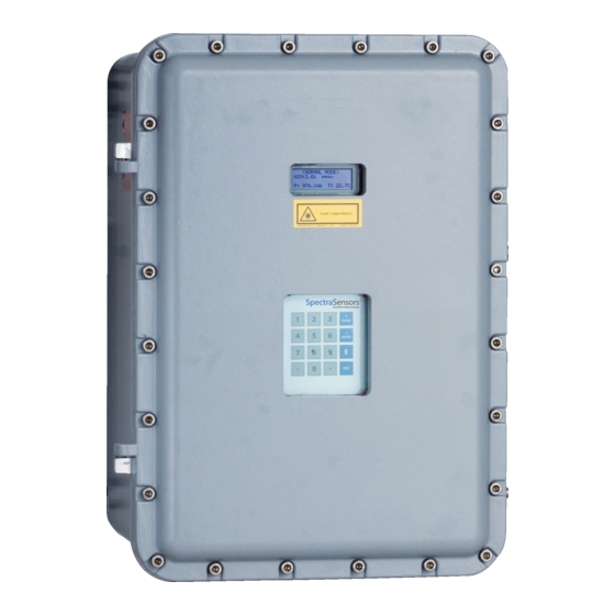
SCS Overview Manual
SS2100i-1 and SS2100i-2 Analyzer
Suitable for Zone 1 Hazardous Location
Copyright © 2021 SpectraSensors, Inc. No part of this manual may be reproduced in whole or
in part without the express written permission of SpectraSensors, Inc. SpectraSensors reserves
the right to change product design and specifications at any time without prior notice.
Advertisement
Table of Contents

Related Manuals for Endress+Hauser SpectraSensors SS2100i-1


Summary of Contents for Endress+Hauser SpectraSensors SS2100i-1
- Page 1 Products Solutions Services 4900002288 Rev B SCS Overview Manual SS2100i-1 and SS2100i-2 Analyzer Suitable for Zone 1 Hazardous Location Copyright © 2021 SpectraSensors, Inc. No part of this manual may be reproduced in whole or in part without the express written permission of SpectraSensors, Inc. SpectraSensors reserves the right to change product design and specifications at any time without prior notice.
-
Page 3: Table Of Contents
ABLE OF ONTENTS List of Figures/Tables ........iii List of Tables . - Page 4 SS2100i-1 and SS2100i-2 Analyzer 4: Validation of Trace Moisture Measurements Validation Methods ..........4-1 Permeation Validation for Trace Moisture (0-10 ppm H O) .
- Page 5 IST OF IGURES ABLES FIGURES Figure 3–1. ATEX/IECEx temperature controller connections ....3-4 Figure 4–1. Schematic of permeation tube ......4-3 Figure 4–2.
- Page 6 SS2100i-1 and SS2100i-2 Analyzer THIS PAGE INTENTIONALLY LEFT BLANK 4900002288 rev. B 1-13-21...
-
Page 7: How To Use This Manual
1 - I NTRODUCTION This manual provides an overview of the sample conditioning system (SCS), including components, operation and troubleshooting that may accompany an SS2100i-1 or SS2100i-2 analyzer. Other manuals related to the operation, installation and maintenance of the SS2100i-1 or SS2100i-2 analyzers may include: •... -
Page 8: Conventions Used In This Manual
SS2100i-1 and SS2100i-2 Analyzer Conventions used in this manual In addition to the symbols and instructional information, this manual is created with “hot links” to enable the user to quickly navigate between different sections within the manual. These links include table, figure and section references and are identified by a pointing finger cursor when rolling over the text. -
Page 9: Equipment Labels
Introduction Equipment labels Warning statement for hazardous voltage. Contact may cause electric shock or burn. Turn off and lock out system before servicing. Failure to follow all directions may result in damage or malfunction of the analyzer. Maximum voltage and current specifications for the fuse closest to label. -
Page 10: Instructional Symbols
Laboratory (JPL) for the purpose of commercializing space-proven measurement technologies initially developed at JPL. SpectraSensors was acquired by the Endress + Hauser Group in 2012. Manufacturer Address SpectraSensors, Inc. An Endress+Hauser Company 11027 Arrow Route Rancho Cucamonga, CA 91730 United States www.spectrasensors.com –... -
Page 11: Potential Risks Affecting Personnel
2 - S AFETY Potential Risks Affecting Personnel Technicians are expected to follow all safety protocols established by the customer that are necessary for servicing the analyzer. This may include, but is not limited to, lockout/tagout procedures, toxic gas monitoring protocols, personal protection equipment (PPE) requirements, hot work permits and other precautions that address safety concerns related to performing service on process equipment located in hazardous areas. -
Page 12: Exposure To Process Gases
SS2100i-1 and SS2100i-2 Analyzer Exposure to process gases 1. Shut off the process gas to the analyzer before any service that would require opening a part of the sample plumbing. 2. Purge the system with nitrogen. 3. Shut off the nitrogen purge before opening any part of the sample system. -
Page 13: 3: Sample Conditioning System
3 - S AMPLE ONDITIONING YSTEM Personnel should have a thorough understanding of the operation of the analyzer and the procedures presented here before operating the sample conditioning system (SCS). The process sample at the sample tap may be at a high pressure. A pressure reducing regulator is located at the sample tap to reduce the sample pressure and allow operation of the sample conditioning system at a low pressure. -
Page 14: Scs Filters
SS2100i-1 and SS2100i-2 Analyzer SCS filters A guard filter is typically installed at the inlet to the SCS with a fine element to protect the flow controllers, flow meters and pressure regulators from fine particulates. A bypass filter with a fritted metal, glass fiber or polymetric membrane filter may also be in place to remove larger quantities of particulates or entrained liquids and mists. -
Page 15: Sample Dryer
Sample Conditioning System Sample dryer All trace measurement applications require the use of a dryer. Typically, these devices are switched into the flowing sample going to the measurement cell to remove the desired component. A spectrum of the sample gas free of H O is acquired and saved in the analyzer controller memory. -
Page 16: Figure 3-1 Atex/Iecex Temperature Controller Connections
SS2100i-1 and SS2100i-2 Analyzer 1. Open the heated enclosure door. Take care not to disturb anything inside. 2. Open the power terminal box inside the heated enclosure, as shown in Figure 3–1 below. Figure 3–1 ATEX/IECEx temperature controller connections 3. Run conduit from the power distribution panel to the conduit hub on the lower right side of the heated enclosure labeled for power input. -
Page 17: Checking The Scs Installation
Sample Conditioning System 4. Pull ground, neutral and hot wires (#14 AWG minimum) into the power terminal box inside the heated enclosure. 5. Strip back the jacket and/or insulation of the wires just enough to connect to the power terminal block. 6. -
Page 18: Starting Up The Scs
SS2100i-1 and SS2100i-2 Analyzer properly at each end, and that each line has been purged clean and pressure tested. 6. Confirm that all valves are closed and all switches are off. 7. Confirm that the AC power is available to the electrically traced sample tubing (if applicable), analyzer, and SCS, but that the local switches are off. -
Page 19: To Start Up The Field Pressure Reducing Station
Sample Conditioning System 7. Confirm that the sample bypass and analyzer flow meter control valves are gently closed (adjustment knob turned clockwise). Do not overtightened the control valves or damage could occur. To start up the field pressure reducing station The process sample at the sample tap may be at a high pressure. Use extreme caution when operating the sample probe isolation valve and field pressure reducing regulator. -
Page 20: To Start Up The Analyzer On Process Sample
SS2100i-1 and SS2100i-2 Analyzer 4. Confirm that the sample supply pressure under flowing conditions is set to the approximate specified pressure. Refer to the analyzer system drawings. Make sure that no liquid, solids, etc. are flowing through the bypass by viewing the flow meter. If substances are present, shut down the system and purge the sample transport lines. -
Page 21: To Start Up The Sample System Heater
Sample Conditioning System 5. Confirm the sample bypass flow and readjust the control valve to the specified setpoint, if necessary. The SCS is now operating with the process sample. 6. Power up the analyzer according to the procedure given for the analyzer in “To power up the analyzer”... -
Page 22: Shutting Down The Scs
SS2100i-1 and SS2100i-2 Analyzer Shutting Down the SCS Situations may occur that require the shutdown of some or all of the SCS. These circumstances may include short-term shutdown for repairs or parts replacements, for example, or a long-term shutdown of the system for packing and storing. -
Page 23: To Isolate The Scs For Short-Term Shutdown
Sample Conditioning System 4. Close the bypass supply shut-off valve. Refer to the analyzer system drawings. If the system will not be out of service for an extended period, it is advised that power remain applied to the sample transport line electric tracer, if applicable, and the sample system enclosure heater. -
Page 24: To Isolate The Process Sample Tap For Long-Term Shutdown
SS2100i-1 and SS2100i-2 Analyzer To isolate the process sample tap for long‐term shutdown If the SCS is to be out of service for an extended period, the SCS must be isolated at the process sample tap. The process sample at the sample tap may be at a high pressure. A pressure reducing regulator is located at the sample tap to reduce the sample pressure and allow operation of the SCS at a low pressure. -
Page 25: Powering Down The Analyzer
Sample Conditioning System 11. Turn off the AC power to the SCS heater and the sample tracer, if applicable, at the power distribution panel. Although power could be shut off to the sample transport line electric tracer, it is advisable to allow this line to remain heated unless the SCS is to be out of service for an extended period or maintenance is required on the line. -
Page 26: Periodic Scs Maintenance
SS2100i-1 and SS2100i-2 Analyzer Periodic SCS Maintenance Due to the chemical properties of the process samples, care must be taken to repair or replace components with proper materials of construction. Maintenance personnel should have a thorough knowledge and understanding of the chemical characteristics of the process before performing maintenance on the SCS. -
Page 27: Regular Scs Status Check
Sample Conditioning System The system must be taken out of service during any cleaning of the sample transport line. If liquid makes it into the analyzer SCS, a filter element may become obstructed leading to a decreasing supply pressure or bypass flow. If obstruction of a filter is observed, the filter should be cleaned and the filter element replaced. - Page 28 SS2100i-1 and SS2100i-2 Analyzer THIS PAGE INTENTIONALLY LEFT BLANK – 4900002288 rev. B 1-13-21...
-
Page 29: 4: Validation Of Trace Moisture Measurements
4 - V ALIDATION OF RACE OISTURE EASUREMENTS The information contained in this chapter is provided for systems designed to detect moisture. The permeation rate and resultant water content of the validation flow have been carefully calibrated at the factory (refer to the analyzer system drawings for the calibrated output of the validation flow). -
Page 30: Setting The Kp Value
SS2100i-1 and SS2100i-2 Analyzer Due to the required conditions, the sample flow pressure regulator, flow control valve and needle valve are factory set and should not be adjusted in the field. The flow components in the sample system are marked with red tags and the message: FACTORY SET - DO NOT FIELD ADJUST. -
Page 31: Figure 4-1 Schematic Of Permeation Tube
Validation of Trace Moisture Measurements WATER VAPOR MEMBRANE Figure 4–1 Schematic of permeation tube The permeation device connects to a “T” assembly between port 6 and 3 of the six-way valve, refer to Figure 4–2 on page 4–4. During normal operating conditions, a portion of the process gas return from the sample cell flows through one end of the “T”... -
Page 32: Figure 4-2 Typical Sample System For Differential Measurement With Permeation Tube Validation Capability
SS2100i-1 and SS2100i-2 Analyzer FLOW SHOWN IN THE ‘OFF’ POSITION CELL 28 m PERMEATION TUBE DRYER SAMPLE SUPPLY SAMPLE RETURN Figure 4–2 Typical sample system for differential measurement with permeation tube validation capability The entire analyzer system is calibrated for operation at the enclosure temperature and sample flow rate specified. -
Page 33: Replacing The Permeation Device
Validation of Trace Moisture Measurements Replacing the Permeation Device The permeation device has a certification period of one year. The device may be used longer than this period if a factory certified validation concentration ) is not required. Over time the permeation tube will lose the water contained inside and the validation concentration will begin to drop steadily. -
Page 34: Resetting The Sample Flow Rate And Recalculating The System Constant Kp
SS2100i-1 and SS2100i-2 Analyzer 5-8 hours The sample system will require to stabilize the temperature of the new permeation device. SpectraSensors does NOT recommend validating the analyzer during the temperature stabilization period. New permeation devices may take up to 21 days to fully stabilize the validation concentration. -
Page 35: To Recalculate The System Constant
Validation of Trace Moisture Measurements 5. Adjust the sample flow rate to obtain 3000 sccm. The 3000 sccm reading is at ml/min at STP. 6. Perform minor adjustments to the valve once the temperature is stable, if necessary. Do NOT adjust the pressure regulator or needle valve without first consulting the Service department. -
Page 36: Connecting The Validation Gas (Optional)
SS2100i-1 and SS2100i-2 Analyzer 3. Calculate the new K 4. Calculate the Standard Deviation of the mean C 5. Calculate the Validation Allowance as 3 * 100. 6. Press #2, enter the Service password and press the * key. 7. -
Page 37: Appendix A: Specifications
Appendix A: Specifications Table A-1 Sample Conditioning System (SCS) Specifications Applications Environmental Temperature –20 C to +50C (–4F to +122 F) (SS2100i-1) Range –10 C to +60C (+14 F to +140 F) (SS2100i-2) Heated Enclosure Operating C to 60 C (122 F to 140 ... - Page 38 SS2100i-1 and SS2100i-2 Analyzer THIS PAGE INTENTIONALLY LEFT BLANK – 4900002288 rev. B 1-13-21...
-
Page 39: Appendix B: Troubleshooting & Maintenance
Appendix B: Troubleshooting & Maintenance This chapter presents recommendations and solutions to common issues related to sample conditioning system (SCS) operation. Contact Service if your SCS does not appear to be hampered by one of these related problems. Refer to “Service Contact” on page B-5. INVISIBLE LASER RADIATION - The sample cell assembly contains a low-power, 10 mW MAX, CW Class 3b invisible laser with... -
Page 40: To Confirm The Relief Valve Setting
SS2100i-1 and SS2100i-2 Analyzer • O-rings (refer to the spare parts list on the associated system USB for specific part numbers) • Permanent ink marker • Non-outgassing grease • Flashlight To confirm the relief valve setting Confirm that the relief valve at the field pressure reducing station has been set to the specified setpoint. -
Page 41: To Replace The Filter
Troubleshooting & Maintenance 4. Clean any liquids or contaminants from the base of the membrane separator. 5. Replace the filter and the O-ring. 6. Place the cap onto the membrane separator and tighten. 7. Check upstream of the membrane for liquid contamination and clean and dry out before re-opening the sample supply valve. -
Page 42: Instrument Issues
SS2100i-1 and SS2100i-2 Analyzer Refer to your analyzer’s spare parts list or contact Service for ordering assistance. Refer to “Service Contact” on page B-5. 6. Connect the female nuts at the top and bottom of the dryer to finger tight. 7. -
Page 43: Service Contact
Number from Service before returning the analyzer to the factory. Your Service representative can determine whether the analyzer can be serviced on site or should be returned to the factory. All returns should be shipped to: SpectraSensors, Inc. An Endress+Hauser Company 11027 Arrow Route Rancho Cucamonga, CA 91730 United States... - Page 44 SS2100i-1 and SS2100i-2 Analyzer and Customer’s sole and exclusive remedy for a breach of warranty is limited to SpectraSensors’ repair or replacement (at SpectraSensors’ sole option) of the product or part thereof which is returned at Customer’s expense to SpectraSensors’ plant. This warranty shall apply only if Customer notifies SpectraSensors in writing of the defective product promptly after the discovery of the defect and within the warranty period.
-
Page 45: Index
NDEX Automatic validation 4–8 Permeation Devices 4–2 Port Check gas supply 4–8 Sample supply 3–7 Power terminal box 3–4 3–5 Powering down the analyzer 3–13 Cautions 1–1 Pressure regulator 3–1 3–6 3–7 3–10 Connecting the optional automatic 3–12 validation 4–8 Control system Tracer 3–6 Sample bypass 3–7... - Page 46 SS2100i-1 and SS2100i-2 Analyzer THIS PAGE INTENTIONALLY LEFT BLANK – Index 4900002288 rev. B 1-13-21...
- Page 47 4900002288 Rev B www.spectrasensors.com/contact...