Endress+Hauser SS2100i-2 Operating Instructions Manual
Tdlas gas analyzer
Hide thumbs
Also See for SS2100i-2:
- Hardware installation and maintenance manual (121 pages) ,
- Operator's manual (114 pages) ,
- Operating instruction (98 pages)

Related Manuals for Endress+Hauser SS2100i-2


Summary of Contents for Endress+Hauser SS2100i-2
- Page 1 BA02197C/66/EN/02.23 70210290 Products Solutions Services Operating Instructions SS2100i-2 TDLAS Gas Analyzer ATEX/IECEx: Zone 1...
- Page 2 Operating Instructions SS2100i-2 TDLAS Gas Analyzer Endress+Hauser...
-
Page 3: Table Of Contents
SS2100i-2 TDLAS Gas Analyzer Operating Instructions Table of Contents 4.12 Connecting the signals and alarms ..... 32 About this document ......4 4.13 Configuring the RS-232/RS-485 converter..34 1.1 Warnings ..............4 4.14 Connecting electrical power to the analyzer ..34 1.2 Symbols on the device.......... -
Page 4: About This Document
European economic area (EEA). Table 2. Symbols U.S. export compliance The policy of Endress+Hauser is strict compliance with U.S. export control laws as detailed on the website of the Bureau of Industry and Security at the U.S. Department of Commerce. - Page 5 Provides the user with an overview of the NS 5.14 firmware functionality. Parameters (NS 5.14) For additional instruction manuals, please refer to the following: • For custom orders, go to the Endress+Hauser website for the list of local sales channels who can provide the requested order-specific documentation: https://endress.com/contact https://addresses.endress.com/ •...
-
Page 6: Introduction
General warnings and cautions Instructional icons are provided in this manual and on the SS2100i-2 unit to alert the user of potential hazards, important information and valuable tips. Following are the symbols and associated warning and caution types to observe when servicing the analyzer. - Page 7 Flammable. Gases used in the processing of this analyzer may be extremely flammable. Any work in a hazardous area must be carefully controlled to avoid creating any possible ignition sources (e.g., heat, arcing, sparking, etc.). Toxins. Endress+Hauser analyzers measure a variety of gases, including high-level H S. Follow all safety protocols governing toxic gases and potential leaks.
-
Page 8: Manufacturer Address
Operating Instructions SS2100i-2 TDLAS Gas Analyzer 2.2.4 Special safety symbols used on the equipment Special safety symbols and labeling are used on the equipment to alert the user to potential hazards and important information associated with the analyzer. Every symbol and label has significant meaning that should be heeded. -
Page 9: About The Gas Analyzers
The tunable diode laser (TDL) absorption spectrometers in the SS2100i-2 operate in the near- to short-wavelength infrared. Each compact sensor consists of a TDL laser light source, sample cell, and detector configured for high sensitivity measurement of a particular component within the gas-phase constituents in the stream. - Page 10 Operating Instructions SS2100i-2 TDLAS Gas Analyzer −1 ��(��) ���� [ �� ( �� ) �� �� (��) Figure 3 below shows the typical raw data from a laser absorption spectrometer scan including the incident laser (), and the transmitted intensity, I(l), for a clean system and one with contaminated mirrors (shown to intensity, I illustrate the system’s relative intensity to mirror contamination).
- Page 11 (ppb) detection levels are possible (depending on target and background species) at real-time response rates. All Endress+Hauser TDLAS gas analyzers employ the same design and hardware platform. Measuring different trace gases in various mixed hydrocarbon background streams is accomplished by selecting a different optimum diode laser wavelength between 700-3000 nm, which provides the least amount of sensitivity to background stream variations.
-
Page 12: Getting Familiar With The Analyzer
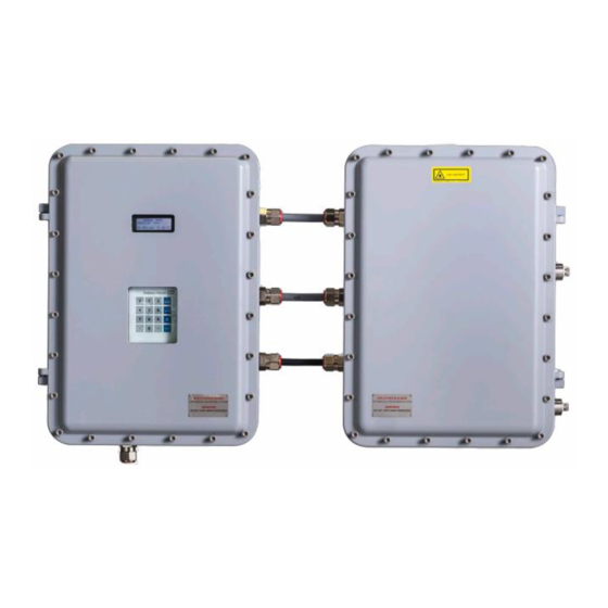
The firmware version for each analyzer is also listed on the analyzer calibration certificate. Getting familiar with the analyzer The SS2100i-2 analyzer consists of two connected enclosures in a standard cable-coupled configuration, as shown in the figure below. Cable & Gland Kit 1100002143 Fig 5. - Page 13 SS2100i-2 TDLAS Gas Analyzer Operating Instructions Endress+Hauser...
- Page 14 Operating Instructions SS2100i-2 TDLAS Gas Analyzer Fig 7. Components in SS2100i-2 electronics enclosure 4-20mA AI board Relay control board Fuse (F3) Temperature control board High temperature limit thermostat ARM9 control electronics Analyzer power supply RS-232 to RS-422/485 converter Relays Solid-state relay...
- Page 15 SS2100i-2 TDLAS Gas Analyzer Operating Instructions Fig 8. Components on an 8 or 28 m sample cell panel enclosure Heater Transition plate thermistor High temp. limit thermostat set at 70 °C Sample temperature thermistor AC terminal block for heater Measurement cell...
- Page 16 Operating Instructions SS2100i-2 TDLAS Gas Analyzer Fig 9. Components on a 0.8 m sample cell panel assembly Heater Transition plate thermistor High temp. limit thermostat set at 70 °C Pressure sensor AC terminal block for heater Measurement cell Terminal blocks...
- Page 17 SS2100i-2 TDLAS Gas Analyzer Operating Instructions Fig 10. Components on a 0.1 sample cell panel enclosure Heater Transition plate thermistor High temp. limit thermostat set at 70 °C Measurement cell AC terminal block for heater Pressure sensor Terminal blocks Sample temperature thermistor In the electronics enclosure, the analyzer power supply provides power to the analyzer control electronics and relays controlling valves.
- Page 18 The temperature controller controls the heater in the sample cell enclosure via the solid-state relay. NOTICE See Fig 7. Components in SS2100i-2 electronics enclosure for locating fuses. If you need to replace a fuse, use only the same type and rating of fuse as the original as listed in the tables below.
- Page 19 SS2100i-2 TDLAS Gas Analyzer Operating Instructions Fig 11. Label placement on exterior of enclosures Chassis ground label Chassis ground label Manufacturer label Port label Class 1 laser product label Endress+Hauser...
- Page 20 Operating Instructions SS2100i-2 TDLAS Gas Analyzer Fig 12. Label placement on electronics panel assembly Electric shock warning label Functional ground earth label Energized fuse warning label 7-8. General warning label General warning label Electric shock warning label Electric shock warning label...
- Page 21 SS2100i-2 TDLAS Gas Analyzer Operating Instructions Fig 13. Label placement on 8 and 28 m sample cell panel Electric shock warning label Class 3-B laser product label Measurement cell rating label Class 3-B laser warning label Do not remove warning label...
- Page 22 Operating Instructions SS2100i-2 TDLAS Gas Analyzer Fig 14. Label placement on 0.8 m sample cell panel Electric shock warning label Do not remove warning label Class 3-B laser product label Class 3-B laser warning label Measurement cell rating label Endress+Hauser...
- Page 23 SS2100i-2 TDLAS Gas Analyzer Operating Instructions Fig 15. Label placement on sample cell panel assembly (0.1 m sample cell) Electric shock warning label Measurement cell rating label Class 3-B laser product label Do not remove warning label Endress+Hauser...
-
Page 24: Safety
Operating Instructions SS2100i-2 TDLAS Gas Analyzer Safety Potential risks affecting personnel This section addresses the appropriate actions to undertake when faced with hazardous situations during or before service of the analyzer. It is not possible to list all potential hazards within this document. The user is responsible for identifying and mitigating any potential hazards present when servicing the analyzer. -
Page 25: Installation
Operating Instructions Installation This section describes the processes used to initially install and configure your SS2100i-2. Once the analyzer arrives, you should take a few minutes to examine the contents before installing the unit. What should be included in the shipping box The contents of the crate should include: •... -
Page 26: Hardware And Tools For Installation
If the protective and chassis ground is insulated, it must use the green/yellow color. WARNING Failure to properly ground the analyzer may create a high-voltage shock hazard. Refer to Fig 7. Components in SS2100i-2 electronics enclosure for locations of the chassis ground connections. Endress+Hauser... -
Page 27: Opening The Analyzer Enclosure Covers
Connect the chassis ground to the marked upper right corner of the right-side enclosure. Connect the chassis ground to the marked bottom left corner of the left-side enclosure. Connect the system ground to the ground bus bar as shown in Fig 7. Components in SS2100i-2 electronics enclosure during the electrical power connection. -
Page 28: Connecting The Solenoid Valves
Operating Instructions SS2100i-2 TDLAS Gas Analyzer Unused cable entries shall be sealed with a flameproof blanking element, which shall be fitted directly to the hole (no threaded adapter shall be used) and shall comply with thread engagement requirements detailed above and shall be secured against loosening. - Page 29 SS2100i-2 TDLAS Gas Analyzer Operating Instructions Fig 17. Basic differential system with two solenoid valves Strip back the jacket and insulation of the solenoid valve cables just enough to connect to the appropriate terminals on the field interface terminal block for your particular sample conditioning scheme, as indicated in the table 31.
- Page 30 Operating Instructions SS2100i-2 TDLAS Gas Analyzer Fig 19. Differential system with single auto-validation requiring two solenoid valves driving three pneumatic valves. Fig 20. Differential system with dual auto-validation requiring four solenoid valves driving eight pneumatic valves Endress+Hauser...
-
Page 31: Application Of Gland Lubricant
4.11 Application of gland lubricant To ensure proper installation, Endress+Hauser recommends using STL8 screw thread lubricant or equivalent on all conduit screw thread and its taped opening. STL8 Screw Thread Lubricant is a lithium based, anti-galling substance with excellent adhesion that maintains rain- tightness and grounding continuity between conduit fittings. -
Page 32: Connecting The Signals And Alarms
Operating Instructions SS2100i-2 TDLAS Gas Analyzer Fig 21. Applying conduit lubricant Screw the female pipe thread onto the male fitting until the lubricated threads are engaged. • Eyes: May cause minor irritation. • Skin: May cause minor irritation. • Ingestion: Non-toxic. Ingestion may result in a laxative effect. Ingestion of substantial quantities may cause lithium toxicity. - Page 33 SS2100i-2 TDLAS Gas Analyzer Operating Instructions NOTICE The 4-20 mA current loop output is factory set to source current. To change the 4-20 mA current loop output from source to sink, see To change the 4-20 mA board from source to sink →...
-
Page 34: Configuring The Rs-232/Rs-485 Converter
Operating Instructions SS2100i-2 TDLAS Gas Analyzer Strip back the jacket and insulation of the alarm output and validation request input cables just enough to connect to the terminals of block (X3). Connect the alarm output and validation request input wires to the appropriate terminals, as indicated in the table below. - Page 35 See Fig 7. Components in SS2100i-2 electronics enclosure → for locating fuses. If you need to replace a fuse, use only the same type and rating of fuse as the original as shown in the following fuse specifications tables. To re-order parts, refer to Analyzer parts →...
-
Page 36: Connecting The Gas Lines
Operating Instructions SS2100i-2 TDLAS Gas Analyzer DWG Ref. Description Rating Miniature Fuse, 5 x 20 mm, Time Delay 250 VAC/1.6 A Miniature Fuse, 5 x 20 mm, Time Delay 250 VAC/0.5 A , F6 , F7 , F8 Miniature Fuse, 5 x 20 mm, Time Delay 250 VAC/0.1 A... -
Page 37: Changing The 4-20 Ma Current Loop Mode
Secure tubing to appropriate structural supports as required. Check all connections for gas leaks. Endress+Hauser recommends using a liquid leak detector. CAUTION Do not exceed 10 PSIG (0.7 barg) in sample cell. Damage to cell may result. - Page 38 Operating Instructions SS2100i-2 TDLAS Gas Analyzer Jumper (JMP1) Re-install the 4-20 mA current loop board and retaining bracket. Reconnect power to the analyzer. Confirm the 4 mA (min.) and 20 mA (max.) points. Refer to the appropriate chapter in the Description of Device Parameters for Scaling and Calibrating the Current Loop Signal →...
-
Page 39: Specifications
SS2100i-2 TDLAS Gas Analyzer Operating Instructions Specifications Performance Concentration See analyzer calibration report Repeatability See analyzer calibration report Measurement time Typically less than 20 seconds Application data –20 C to 50 C (–4 F to 122 F) — Standard Environmental temperature range –30 C to 60 C (–14 F to 140 F) —... -
Page 40: Exd Accessory Conditions Of Use
Operating Instructions SS2100i-2 TDLAS Gas Analyzer Area classification Analyzer (electronics and laser) ATEX / IECEx / INMETRO II 2 G Ex db IIB+H2 T4 Gb –20 °C ≤ Tamb ≤ +60 °C CML 21 ATEX 11305X ; IECEx CML 21.0154X; CPEx 23.1043X CE... - Page 41 SS2100i-2 TDLAS Gas Analyzer Operating Instructions Endress+Hauser...
-
Page 42: Maintenance And Troubleshooting
Operating Instructions SS2100i-2 TDLAS Gas Analyzer Maintenance and troubleshooting WARNING INVISIBLE LASER RADIATION — Avoid exposure to beam. Class 3b Radiation Product. Refer servicing to the manufacturer-qualified personnel. CAUTION The optical head has a seal and “WARNING” sticker to prevent inadvertent tampering with the device. Do not attempt to compromise the seal of the optical head assembly. -
Page 43: Cleaning The Mirrors
If contamination makes its way into the cell and accumulates on the internal optics, a Laser Power Low Alrm fault will result. Cleaning the mirrors If mirror contamination is suspected in your SS2100i-2, contact Service before attempting to clean the mirrors. Refer to Service → . If advised to do so, use the following procedure. - Page 44 Operating Instructions SS2100i-2 TDLAS Gas Analyzer 6.5.2 Determining the type of cell mirror Measurement cells will come equipped with either a glass or stainless steel mirror. Before determining whether to clean or replace the mirror, identify the type of measurement cell being used in the analyzer. There are four types of measurement cells;...
- Page 45 Cleaning the mirror NOTICE Endress+Hauser does not recommend cleaning the top mirror. If the top mirror is visibly contaminated, refer to Service → Careful marking of the mirror orientation is critical to restoring system performance upon reassembly after cleaning.
- Page 46 Operating Instructions SS2100i-2 TDLAS Gas Analyzer Replace mirror and components Carefully replace the mirror assembly onto the cell in the same orientation as previously marked. Add a very thin layer of non-outgassing grease to the O-ring. Replace the O-ring and ensure it is properly seated.
-
Page 47: Replacing The Pressure Sensor
SS2100i-2 TDLAS Gas Analyzer Operating Instructions Check the O-ring. If a new O-ring is needed, apply grease on fingertips and then to the new O-ring. Place newly greased O-ring into the groove around the outside of the mirror taking care not to touch the mirror surface. - Page 48 Operating Instructions SS2100i-2 TDLAS Gas Analyzer Disconnect the measurement cell outlet using a in wrench. Disconnect the thermistor cable at the circular connector. Remove the pressure sensor cable from the circular connector inside the enclosure. For newer model pressure transducers with quick-disconnects, detach the pressure sensor cable from the pressure sensor at the connector using a Phillips-head screwdriver.
- Page 49 SS2100i-2 TDLAS Gas Analyzer Operating Instructions Fig 32. Removing the old pressure sensor Turn the ⅞ in wrench counterclockwise to loosen the pressure sensor until it can be removed. Replace the pressure transducer Remove excess seal tape from the threads at the opening and check for galling.
- Page 50 Operating Instructions SS2100i-2 TDLAS Gas Analyzer Remove the new pressure sensor from the packaging. Retain the black connector cap on the sensor. Do not remove the cap. Wrap stainless steel PTFE tape around the threads at the top of the pressure sensor, beginning from the base of the threads to the top, approximately three times taking care to avoid covering the top opening.
- Page 51 SS2100i-2 TDLAS Gas Analyzer Operating Instructions NOTICE If the newer model pressure sensor cable is currently installed in the SCS, a new cable may not be required. If no new cable is installed, re-attach the existing cable. Mount the cell to the mounting brackets using a in Allen wrench with the pressure sensor facing out towards the cabinet door.
- Page 52 Operating Instructions SS2100i-2 TDLAS Gas Analyzer Purge the system by connecting dry nitrogen to the sample inlet. Allow the SCS to purge for 5 to 10 minutes. Close the nitrogen flow. Power off the system. Refer to the Description of Device Parameters →...
- Page 53 SS2100i-2 TDLAS Gas Analyzer Operating Instructions Hold the wrench on the flange stable and parallel to the surface. Do not move. Turn the ⅞ in wrench counterclockwise to loosen the pressure sensor until it can be removed. Replace the pressure sensor Remove excess seal tape from the flange opening and threads and check threads for galling.
- Page 54 Operating Instructions SS2100i-2 TDLAS Gas Analyzer Fig 42. Replacing the pressure sensor. Using the in wrench to hold the flange in place, turn the sensor clockwise with a ⅞ in wrench until tight. Two or three threads on the pressure sensor should still be visible.
- Page 55 SS2100i-2 TDLAS Gas Analyzer Operating Instructions Power on the system and run validation Turn the system power on. Refer to the Standard documentation → for this analyzer for Powering up the analyzer. Run a validation on the analyzer. Refer to the Standard documentation →...
-
Page 56: Flame Arrestor Replacement And Safety
Operating Instructions SS2100i-2 TDLAS Gas Analyzer NOTICE Contact Service for any questions related to leak testing. Refer to Service → Flame arrestor replacement and safety The analyzer system comes equipped with a protective covering over the flame arrestors and tubing that runs from the analyzer electronics to the SCS. - Page 57 SS2100i-2 TDLAS Gas Analyzer Operating Instructions Fig 46. Flame arrestor positions inside the enclosure Top flame arrestor Bottom flame arrestor Remove the flame arrestor using a ⅞ in wrench. After the seal is broken, the flame arrestor may be loosened by hand and removed.
- Page 58 Operating Instructions SS2100i-2 TDLAS Gas Analyzer • Eyes: Direct contact with eye can cause mechanical irritation. • Skin: The material (when in wet state or as a dust) is not chemically harmful if it comes in contact with the skin and is not immediately washed off.
-
Page 59: Peak Tracking Reset Procedure
Refer to the Standard documentation → for this analyzer for instructions to capture diagnostic data and submit to Endress+Hauser, refer to Service → Null fail Refer to the Description of Device Parameters for your analyzer for instruction. - Page 60 Check connections on keypad cable. have specified effect Reading seems to always be high by Capture diagnostic data and send the file to Endress+Hauser (refer to the section called “To a fixed amount read diagnostic data with HyperTerminal” in the Standard documentation →...
-
Page 61: Service
Packing, shipping, and storage Endress+Hauser analyzer systems and auxiliary equipment are shipped from the factory in appropriate packaging. The SS2100i-2 analyzer is typically packed in a wooden crate. All inlets and vents are capped and protected when packaged for shipment. -
Page 62: Storage
Warranty For a period of 18 months from date of shipment or 12 months in operation, whichever comes first, Endress+Hauser warrants that all products sold by it shall be free from defects in material and workmanship under normal use and service when correctly installed and maintained. -
Page 63: Analyzer Parts
Operating Instructions Analyzer parts This chapter provides lists and illustrations of all field replaceable parts used in the SS2100i-2 analyzer. Due to a policy of continuous improvement, parts and part numbers may change without notice. Not all parts listed are included on every analyzer. When ordering, please specify the system serial number (S/N) to ensure that the correct parts are identified. - Page 64 Operating Instructions SS2100i-2 TDLAS Gas Analyzer Fig 49. Electronics panel assembly parts (Continued) Fig 50. Electronics panel assembly parts (Continued) Endress+Hauser...
- Page 65 SS2100i-2 TDLAS Gas Analyzer Operating Instructions Figure Number Reference Number Material Number Description Fig 51 70159149 Circuit Breaker, 9926 Series Fig 51 70156874 Terminal Block Fuse, UK 5-HESILA 250, Un-500V, In-6.3A Fig 51 70156930 Fuse, Miniature, 5 x 20 mm, 0.5 A...
- Page 66 Parts for 8/28 m sample cell panel assembly Contact Endress+Hauser Service department before attempting replacement. Replacing this component without Service support could cause damage to other components. For Service, refer to our website for the list of local sales channels in your area (www.endress.com).
- Page 67 Parts for 0.8 m sample cell panel assembly Contact Endress+Hauser Service department before attempting replacement. Replacing this component without Service support could cause damage to other components. For Service, refer to our website for the list of local sales channels in your area (www.endress.com).
- Page 68 Parts for 0.1 m sample cell panel assembly Contact Endress+Hauser Service department before attempting replacement. Replacing this component without Service support could cause damage to other components. For Service, refer to our website for the list of local sales channels in your area (www.endress.com).
- Page 69 SS2100i-2 TDLAS Gas Analyzer Operating Instructions Figure Number Reference Number Material Number Description Fig 58 70156940 Keypad, Touch Sensitive, 16 Keys Fig 58 70159096 Display, LCD, 20X4, Backlit, 5 V, Serial Parts for electronics enclosure assembly Fig 58. Analyzer electronics enclosure assembly...
- Page 70 Kit, Cleaning Tools, Optical Cell (International) Non-SAP part number Contact Endress+Hauser Service department before attempting replacement. Replacing this component without Service support could cause damage to other components. For Service, refer to our website for the list of local sales channels in your area (www.endress.com).
- Page 71 Material Number Description 1100002156 Tooling Kit (Installation/Maintenance) General BA02197C SS2100i-2 TDLAS Gas Analyzer Operating Instruction, additional copies GP01177C Description of Device Parameters FS 5.16, additional copies XA02694C SS2100i-2 TDLAS Gas Analyzer Safety Instruction, additional copies GP01180C Description of Device Parameters NS 5.14, additional copies...
-
Page 72: Wiring Diagrams
Operating Instructions SS2100i-2 TDLAS Gas Analyzer Wiring diagrams Fig 59. Wiring schematic of SS2100i-2 electronics power systems Fig 60. Wiring schematic of conduit-coupled SS2100i-2 power system Endress+Hauser... - Page 73 SS2100i-2 TDLAS Gas Analyzer Operating Instructions Fig 61. Wiring schematic of SS2100i-2 digital I/O Fig 62. Wiring schematic of SS2100i-2 alarms Endress+Hauser...
- Page 74 Operating Instructions SS2100i-2 TDLAS Gas Analyzer Fig 63. Wiring schematic of SS2100i-2 serial and Ethernet signals Fig 64. Wiring schematic of SS2100i-2 inter-card connections Endress+Hauser...
- Page 75 SS2100i-2 TDLAS Gas Analyzer Operating Instructions Fig 65. Wiring schematic of conduit-coupled SS2100i-2 optical head connections Fig 66. Wiring schematic of conduit-coupled SS2100i-2 pressure and temperature sensor connections Endress+Hauser...
- Page 76 Operating Instructions SS2100i-2 TDLAS Gas Analyzer Fig 67. Wiring schematic of cable-coupled SS2100i-2 power system Fig 68. Wiring schematic of cable-coupled SS2100i-2 optical head connections Endress+Hauser...
- Page 77 SS2100i-2 TDLAS Gas Analyzer Operating Instructions Fig 69. Wiring schematic of cable-coupled SS2100i-2 pressure and temperature sensor Fig 70. Wiring schematic of conduit-coupled SS2100i-2 sample cell plate connections Endress+Hauser...
- Page 78 Operating Instructions SS2100i-2 TDLAS Gas Analyzer Fig 71. Wiring schematic of cable-coupled SS2100i-2 sample cell plate connections Endress+Hauser...
- Page 79 SS2100i-2 TDLAS Gas Analyzer Operating Instructions www.addresses.endress.com Endress+Hauser...