Table of Contents
Advertisement
Quick Links
Advertisement
Chapters
Table of Contents

Related Manuals for Omron NT20M


Summary of Contents for Omron NT20M
- Page 1 Cat. No. V001-E1-2 NT20M/NT2000M Programmable Terminal...
- Page 2 NT20M/NT2000M Programmable Terminal Operation Manual Revised September 1993...
- Page 4 OMRON. No patent liability is assumed with respect to the use of the information contained herein. Moreover, because OMRON is constantly striving to improve its high-quality products, the information contained in this manual is subject to change without notice.
-
Page 6: Table Of Contents
TABLE OF CONTENTS SECTION 1 Introduction ........Introduction . - Page 7 SECTION 7 Online Transfer ........Transferring Screen Data .
-
Page 8: Introduction
Section 7 describes transferring screens online to and from the host computer. Section 8 provides troubleshooting and basic maintenance methods, including battery replacement. Appendices of OMRON products used with PTs and PT specifications are provided at the back of the manual. -
Page 9: Features
1-4-1 NT20M Programmable Terminals ........ - Page 10 Section 1-1 Features Introduction This manual describes the installation and operation of NT20M and NT2000M Programmable Terminals (PTs). Both models can come with or without touch panels. Programmable Terminals have three main functions: 1) monitoring operating conditions, 2) directing on-site personnel, and 3) input- ting data.
-
Page 11: Nt-Series Terminology
Direct connection is possible for PTs with touch panels when a Host Link Interface Unit is mounted. In addition, the NT20M- ZASAT-EV4 Support Tool and the NT20M-SMR31-E are required. - Page 12 Models 1-4-1 NT20M Programmable Terminals The various NT20M PT models are shown in the table below. Several of these models employ two-color backlights. The two-color backlight incorpo- rates red and white lights, one of which is selected according to operational requirements.
- Page 13 (changeable between white and red), which is replaceable and is sold separately. The NT2000M-DN131, like the NT20M models described above, does not come with an image data memory chip mounted. This must be purchased separately.
- Page 14 Support Tool Screen data, memory table data, and system data are all created by the Sup- port Tool. In order to fully utilize the functions of the NT20M and NT2000M PTs, use a Support Tool version of NT20M-ZASAT-EV4 or higher. Screen data is interchangeable for NT20M and NT2000M PTs.
- Page 15 Section 1-6 System Configuration RS-422 Interface Using NT600M-LK202 Host Interface Units, up to 16 NT20M or NT2000M (NT600M-LK202) Programmable Terminals can be connected to a PC through an ASCII Unit, or to an FA computer. C-series PC FA computer ASCII Unit...
-
Page 16: Nomenclature And Functions
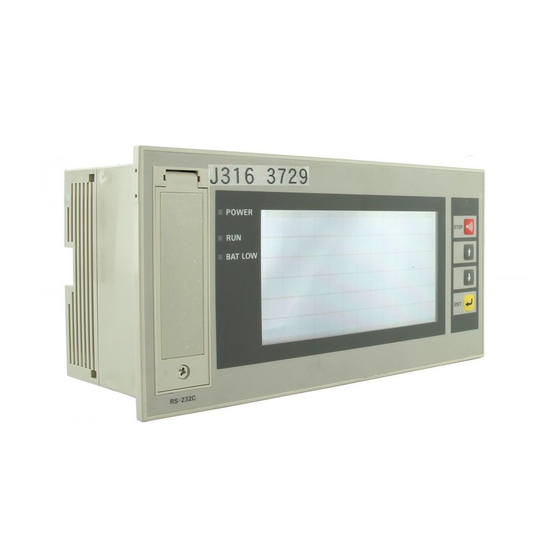
Lit while power is on. System Keys RUN Indicator (green) Used when maintenance of the Lit during operation NT20M, selecting the System BAT LOW Indicator (red) Menu, etc. Used during operation Lights if the lithium for scrolling the screen and input- battery voltage level ting numeric values. - Page 17 Remove seal when connecting a 12-key Function Key Unit. Components under Drip-Proof Cover NT20M-Dj121-V2 The illustration below is for the NT20M-Dj121-V2. The NT20M-Dj13j is basically similar except for the contrast control being in a slightly different position. Contrast Control Reset Switch Adjusts display contrast.
- Page 18 Section 1-7 Nomenclature and Functions 1-7-2 NT2000M-Dj131 Front Panel Display POWER Indicator (Green) BAT LOW Indicator (Red) Normally lit when power is Lights when the voltage level turned on. of the lithium battery drops. RUN Indicator (Green) Lit during operation. Note When no battery is installed, BAT LOW indicator operation is unstable.
- Page 19 Section 1-7 Nomenclature and Functions Components Under the Connector Cover Peripheral Device Interface Connector Transfers image data between the NT2000M and a pe- ripheral device. Buzzer Sound Enable/Disable Pin Lithium battery When this pin is pulled out, the buzzer will not sound under any conditions.
-
Page 20: Section 2 Settings And Installation
2-3-1 NT20M Programmable Terminals ........ -
Page 21: Switch Settings
Section 2-1 Switch Settings Switch Settings There are switches to set under the switch cover on the back of the Terminal, and also on each Host Interface Unit. For Host Interface Unit switch settings, refer to the Host Interface Unit Operation Manual. Be sure to set the switches before installation if the installation location prevents access to the switches after installation. -
Page 22: System Rom Mounting
2. Be sure to lock the System ROM after mounting, otherwise the operation of the PT will be unstable. 3. OMRON Corporation has the copyright of the System ROM program. Making a copy of the program is prohibited without the prior consent of the OMRON Corporation. -
Page 23: Installation Environment
Avoid installing the PT in a location where any of the following conditions ex- ist. • Ambient temperatures exceeding a range of 0°C to 45°C for the NT20M or 0°C to 50°C for the NT2000M. • Abrupt temperature changes or condensation. -
Page 24: Dimensions
(such as solenoids), allow a distance of at least 40 mm, more if neces- sary. Solenoid 40 mm min. Solenoid 40 mm min. Dimensions All dimensions are in millimeters. 2-3-1 NT20M Programmable Terminals Terminals With and Without Touch Panels Approx. Cable... -
Page 25: Nt2000M Programmable Terminals
76.8 Cable Installing in a Panel The NT20M is designed to be installed in a panel. Install it as follows: 1, 2, 3... 1. Cut a hole in the panel in accordance with the recommended dimen- sions shown below. The panel should be between 1.6 and 4.8 mm thick. - Page 26 Side Space for Backlight Replacement: When mounting the NT20M to a panel, leave open the space marked with dotted lines on the left of the rear panel as shown below. 175 mm min.
- Page 27 NT20M case. NT20M Turn the screw with the tool that comes with the NT20M, and secure the NT20M to the panel. When you are finished, rotate the tool in the re- verse direction and remove it from the screw.
-
Page 28: Wiring And Connectors
M3.5 screws. For the NT2000M, use crimp-style terminals with holes to match M4 screws. The dimensions shown in the illustration below are for the NT20M. For the NT2000M, the di- mensions would be 8.6 mm max. for both the fork-type and the round-type. -
Page 29: Power Supply And Battery Wiring
2Y-3.5 2-3.5 2Y-4 2-5-2 Power Supply and Battery Wiring 24 VDC (NT20M) These are the power supply input terminals for running the NT20M. Breaker 24-VDC power supply NT20M Power Supply Wiring • Provide 24-VDC power. • Use a power supply within the allowable voltage range. -
Page 30: Lg And Gr Terminals
Section 2-5 Wiring and Connectors AC Input (NT2000M) These are the power supply input terminals for running the NT2000M. MCCB 100 to 240 VAC Insulated 50/60 Hz transformer NT2000M Power Supply Wiring • Provide a 100 to 240 VAC power. •... -
Page 31: Host Run Input Terminal
This condition will be maintained until the host RUN status is restored. Enable: Turn OFF SW1, pin 2. Disable: Turn ON SW1, pin 2. NT20M NT20M 24 VDC Host Host RUN status with transistor ON. -
Page 32: Alm Output (Alarm Output)
Section 2-5 Wiring and Connectors Input Specifications (For Both NT20M and NT2000M) Item Content +10% Rated input voltage 24 VDC –15% Input impedance 5.6 kΩ Input current 4.1 mA typical (at 24 VDC) ON voltage 15.5 V min. OFF voltage 5.0 V max. -
Page 33: Rs-232C Interface Connector
FG (Not connected.) Shielded wire D-sub connector, 9 pins Note 1. RS-232C communications conditions are set automatically by the NT20M Support Tool. 2. Connectors can be connected and disconnected with power turned on. 3. This connection diagram cannot be used for the Host Interface Unit. -
Page 34: Mounting Function Key Units (To Dn-Type Pts)
Mounting Function Key Units (to DN-type PTs) Section 2-7 Applicable Connectors Plug: XM2A-0901 (OMRON) or equivalent. (Cable Side) Hood: XM2S-0911 (OMRON) or equivalent. Recommended Cables AWG 28 x 5P IFVV-SB (Fujikura Cable, Ltd.) CO-MA-VV-SB 5P x 28 AWG (Hitachi Cable, Ltd.) Cable Set CV500-CN228 (OMRON) -
Page 35: Section 3 Initial Operation
SECTION 3 Initial Operation This section provides an introduction to the operations necessary to use a PT for the first time and to the menus and keys used to control PT operation. Powering Up ............. Initialization . -
Page 36: Powering Up
Section 3-1 Initialization Powering Up When first starting up the system, do not connect the Host Interface Unit to the host. When power is turned on to the PT, either a “Connecting to host” message or the initial screen set by the Support Tool will be displayed. The “Connecting to host”... -
Page 37: Menus
Section 3-1 Initialization If you select no, then operation will begin without initialization. When entering RUN Mode after initialization, nothing will be displayed on the screen and the Terminal will wait for a command from the host. Caution Screen memory must be initialized before using a new PT. If the PT is used as shipped from the factory without initialization, messages indicating errors in the host will not be displayed properly. -
Page 38: Transferring Data To And From The Support Tool
Section 3-3 Transferring Data to and from the Support Tool Error Messages When there is an error in screen data registered in the PT, the System Menu will appear before entering RUN Mode, and the error message will be dis- played on the bottom line. -
Page 39: Initial Settings
Section 3-4 Initial Settings Perform the transfer operation from the Support Tool. The screen shown below will be displayed during the transfer. PT --> Host Shows direction Transmit Mode Host --> PT of data transfer. Screen Data System Memory Memory Tables Shows type of data. -
Page 40: Section 4 Display Functions
SECTION 4 Display Functions This section describes the functions used to create screens and control display attributes on the PT. Functions used to in- put data on-screen are described in Section 5 Input Functions. Data transfer and maintenance functions are described in Section 6 System Menu. -
Page 41: Character Displays On Screen
Character Displays on Screen The type, size, and attributes of characters that can be displayed on the NT20M and NT2000M screens are shown below. Character type, size, and attributes are set at the time of creation on the Support Tool. When an RS-232C or RS-422 Host Interface Unit is used, coordinates, characters, etc., can be designated with commands from the host in Terminal Mode. -
Page 42: Procedure For Changing Screens
When an ordinary screen is displayed, the screens cannot be changed by means of the Up and Down Keys on the front panel of the NT20M. For details on screen-changing procedures for each interface, refer to the Host Interface Unit Operation Manual. -
Page 43: Overlapping Screens
Section 4-4 Overlapping Screens • Screens with numeric settings cannot be designated as a child screen for any consecutive screen. • A continuous screen cannot be registered as a child screen. Note The parent screens (screen no. 09 in this case) cannot have screen data. They can be treated only as parent screens. -
Page 44: Numeric Displays
Section 4-5 Numeric Displays Numeric Displays A numeral table is stored in the PT, and you can display numeric values from the table at programmed positions on a screen. In addition, the values in the table can be transferred from the host so that they are renewed each time a new value is transferred. -
Page 45: Character Strings
Section 4-6 Character Strings Character Strings This function displays variable character strings on the screen. These char- acter strings can be changed with transmissions from the host. A character string memory table is stored in the PT. By changing, from the host, the memory table values corresponding to the display position, you can update the characters displayed. -
Page 46: Bar Graphs
Section 4-8 Lamps Bar Graphs If the numeric values that you want to make into a bar graph have been input into the numeral table in advance, then that graph can be displayed simply by designating the screen on which the graph is registered. Just as with nu- meric displays, the graph display is also updated when the contents of the numeral table are updated. -
Page 47: Graphics Display
Section 4-10 Special Controls Number of settings: The total number of lamps must not be greater than 64 per screen. Display attribute: Lit or flashing (used for bit designation). Guide characters: With or without (selectable). Lamps set from the host can be turned on and off by either of two methods: number designation or bit designation. -
Page 48: Backlight Red/White
4-10-2 Backlight Red/White The backlight can be changed from white to red during operation. This is possible for the following models: NT20M-DT13j/DN131 and NT2000M-Dj131. 4-10-3 Buzzer On/Off The built-in buzzer can be turned on and off from the host. There are two types of buzzers, continuous and intermittent. - Page 49 Section 4-10 Special Controls 4-10-7 Terminal Function This function allows you the option of displaying, by transmission on com- mand, the codes (coordinates, type, etc.) of characters and figures you want to display from the host, in addition to screens registered in advance. This function is possible only when the Host Interface Unit is the NT600M-LK201 (RS-232C specifications) or the NT600M-LK202 (RS-422 specifications).
-
Page 50: Section 5 Input Functions
SECTION 5 Input Functions This section describes the functions used to input data on-screen. Functions used to create screens and control display attributes on the PT are described in Section 4 Display Functions. Data transfer and maintenance functions are described in Section 6 System Menu. -
Page 51: On-Screen Switch Inputs
Section 5-1 On-screen Switch Inputs On-screen Switch Inputs The DT-type PT can transmit to the host the status of touch switches set on screens. A maximum of 64 switches can be set per screen. The DN-type can transmit to the host the inputs of 12-key Function Key Units and External I/O Units. -
Page 52: Using Function Keys
12-key Function Key Unit or an External I/O Unit is connected to a DN-type PT, the functions of the keys can be allocated. Up to two function keys can be pressed simultaneously when using an NT20M-FK210 Function Key Unit. Example of Function Key Input Screen... - Page 53 Inputting Numeric Values Use the 12-key Function Key Unit (NT20M only) or the 32/16 Terminal for an External I/O Unit. The 10/02 Terminal cannot be used for numeric input. (PTs Without Touch Panels) 1) Inputting Numeric Values with the Standard Screen: Use the corresponding function keys.
- Page 54 Section 5-2 Inputting Numeric Settings 2) Inputting Numeric Values with a User-set Screen: Use the corresponding function keys. Numeric input is the same as for PTs with touch panels. Numeric Input Example This example shows numeric input with a user-set screen. The display set- tings made with the Support Tool are as follows: Number of digits displayed: Number of integer digits:...
-
Page 55: Standalone Function
Standalone Function Section 5-3 1) When System Keys are Used: When system keys are used, the cursor moves from area to area in the order in which the areas were created by the Support Tool. Thus, in the screen ex- ample shown above, the cursor would start at numeric setting 2 and move in order to numeric settings 3, 4, 5, and back to 1. -
Page 56: Section 6 System Menu
SECTION 6 System Menu This section describes data transfer and maintenance functions. Functions used to create screens and control display at- tributes on the PT are described in Section 4 Display Functions. Functions used to input data on-screen are described in Section 5 Input Functions. -
Page 57: Configuration Of System Menu
Section 6-1 Configuration of System Menu Configuration of System Menu The system menu is used to set PT system parameters in advance and per- form maintenance. With the system menu you can, in addition to determining the PT’s status, check switch settings and perform simple I/O checks. (1) If there is no key input within 10 s, the original screen will be automatically reset. -
Page 58: System Menu
Section 6-3 Maintenance Mode System Menu 6-2-1 Quit The System Menu is called up by using the system keys during operation. To leave the System Menu and return to RUN Mode, select Quit. If no key is pressed for 10 seconds, the PT will automatically return to RUN Mode. SYSTEM MENU Quit Transmit Mode... - Page 59 Section 6-3 Maintenance Mode Whenever the screen number registered for history attributes is designated by the host, the occurrence and message are saved in memory. • The capacity of the history is 256 screens. • The only things that can be recorded are screen numbers and messages. History record data is backed up by a battery, so, as long as the lithium bat- tery is installed, the contents will be retained even when the power is turned off.
- Page 60 Section 6-3 Maintenance Mode • One screen displays six items of record data. • If not all of the record data shows on the screen, then use the Down Key to scroll down. • To return to RUN mode, press the Buzzer Key, Up Key, and Down Key si- multaneously.
- Page 61 Up to two keys can be pressed simultaneously. The NT20M-FK210 has 12 standard function keys, so you can use F1 to F12. To return to the I/O Check Menu, press the Buzzer Key, Up Key, and Down Key simultaneously.
- Page 62 Section 6-3 Maintenance Mode To return to the I/O Check Menu, press the Buzzer, Up, and Down system keys simultaneously. F57 F58 F61 F62 F63 F64 F59 F60 Lamp Output Check When “lamp output check” is be displayed in reverse video, L1 will light. This in- dicates that output 1 is ON.
- Page 63 If “Backlight” is selected, the cycle from white (1 s) to red (1 s) to off will be repeated. To stop the backlight check, press the Buzzer Key, Up Key, and Down Key simultaneously. The NT20M-DT121-EV2 and the NT20M- DN121-EV2 do not have red backlights.
- Page 64 Section 6-3 Maintenance Mode There are two screens, one for the PT and one for the Host Interface Unit, and you can scroll up and down with the Up and Down Keys. Internal Settings When PT Settings is selected, the internal settings of the PT are displayed first.
-
Page 65: Memory Switch Settings
After the settings have been made, press the Buzzer, Up, and Down keys to re- turn to RUN Mode. If the power to the NT20M is turned off at this point, the set- tings will not be registered. - Page 66 NT20M power turns off or a reset is executed. If power to the NT20M is turned off or a reset is executed, the contents of the memory table are overwritten by the contents of data created by the Support Tool.
- Page 67 Memory Switch Settings Section 6-4 When any one of the above key inputs or commands is received, the backlight will be turned back on and the internal timer will start counting again. If a key in- put or command is then received before the time is up, the timer will be reset and the count will start over.
-
Page 68: Online Transfer
SECTION 7 Online Transfer This section describes transferring screens online to and from the host computer. Functions used to create screens and control display attributes on the PT are described in Section 4 Display Functions. Functions used to input data on-screen are described in Section 5 Input Functions. -
Page 69: Transferring Screen Data
Section 7-2 PT to Host Transferring Screen Data Screen data can be transferred along with screen numbers. Set the desired screen number. If you set a screen number which is identical with one al- ready registered in the PT, then the screen data for that number will be over- written. -
Page 70: Online Transmission And Resume Function
Section 7-2 PT to Host Online Transmission and Resume Function Online transfer enables the Host to write data directly to the screen data memory just like data transfer to the Support Tool. Therefore, the contents of the display are influenced by the settings of the resume function. Display after data reception Display after reception of data from the Host... -
Page 71: Section 8 Maintenance And Inspection
SECTION 8 Maintenance and Inspection This section provides troubleshooting and basic maintenance methods, including battery replacement. Checking Operation ............Changing the Lithium Backup Battery . -
Page 72: Checking Operation
Provide a power supply with a rated voltage of 24 VDC. does not light. supply is connected in inverse. Do not reverse polarity. A fuse is blown. Contact your OMRON representative. Message indicates no No Host Interface Unit is mounted. Mount a Host Interface Unit. Host Interface. -
Page 73: Changing The Lithium Backup Battery
Changing the Lithium Backup Battery Changing the Lithium Backup Battery A lithium battery is used in the NT20M and in the NT2000M. If the BAT LOW indicator on the front panel lights, replace the battery within ten days. Battery model... -
Page 74: Replacing The Backlight
Section 8-4 Maintenance and Inspection Replacing the Backlight The backlight can be replaced for NT20M-DT13j, NT20M-DNj, and NT2000M-Dj131 PTs. When the screen begins to flicker or get darker, re- place the backlight by replacing the CFL Unit. CFL Unit model... -
Page 75: Maintenance And Inspection
Section 8-4 Maintenance and Inspection NT2000M-Dj131 1) Turn off the power to the PT. Backlights 2) Remove the backlight case at the rear of the PT, by pressing on the place where it is indicated and pushing upward. Hooks 3) Pull off the attached CFL Unit connector and remove the CFL Unit. Latches CFL Unit Connector... -
Page 76: Maintenance And Inspection
PT. • When returning a defective PT for service, please describe the problem in as much detail as possible. Send the PT to the OMRON office closest to you. - Page 77 NT20M-CFK01 Key Sheets (Five Sheets) Use these sheets for NT20M-FK210 function keys. By simply peeling them off of the paper, you can easily write on them and attach them. You can also rub off anything written with oil-base ink. If they get dirty, you can easily remove and replace them.
- Page 78 NT20M-KBA03 Oil Resistance Kit Mount this kit to the display panel of the NT20M to protect from dirt and oil. (This kit cannot be mounted at the same time as an NT20M-FK210 Function Key Unit. In addition, when it is mounted it is not possible to access under the Support Tool connector cover.
- Page 79 Enclosure ratings Front control panel IP52F (Drip-proof IP65F or equivalent. Do not expose to when dust cover is installed, as long as direct jet stream for longer than one NT20M-FK210 is not mounted.) minute. Rear case: IP20 Terminal section IP00 Weight 1.2 kg max.
- Page 80 ±40° (when white backlight is lit) NT20M-Dj13j ±45° (when red backlight is lit) NT2000M-Dj131 Backlight White cold-cathode tube (NT20M-Dj13j and NT2000M-Dj131 can change between red and white backlights.) Service life expectancy: 10,000 hrs min. (20,000 hrs average) Automatic turn-off: Can be set to not turn off, or to turn off in 10 min or 1 hr...
- Page 81 Special Features Item Specifications Alarm output Relay output on rear terminal block. Rating: NT20M: 1 A at 24 VDC NT2000M: 1 A at 24 VDC Output condition: NO contact (Closes when a command is received from the host or when there is a screen called with an alarm-ON specification.) Host RUN input Photocoupler input on rear terminal block.
-
Page 82: Index
Index function key input screen, 47 abbreviations, 3 function keys, checking, 56 alarms, controlling from host, 43 ALM OUTPUT terminals, 25 ASCII Unit, 6, 7 host computer controlling PT operation, 42 data transfer, 39, 40, 41, 44, 46, 47 Host Interface Units, displaying settings, 58 backlight, controlling from host, 42 Host Link Unit, interface, 7, 8 bar graphs, displaying, 41... - Page 83 Index menus overview, 31 selecting items, 31 screen memory, initializing, 60 system menu, 52 screens changing, 36 mode changes, enable/disable setting, 14 continuous screens, 37 examples, 36 models, 4 maximum limit, 5 overlapping screens, 38 transferring online, 64 setting, defaults, 33 specifications, 75 special features, 77 string table, 40...
-
Page 84: Revision History
Page 23: “Transfer Mode” has been changed to “Transmit Mode” within the procedure. Page 26: The description within 4-1-3 Character Scale has been changed. Page 32: NT20M-LB121-EV1 Host Interface Unit has been added to the Note at the bottom of the page. - Page 85 The Netherlands Tel: (31)2356-81-300/Fax: (31)2356-81-388 OMRON ELECTRONICS LLC 1 East Commerce Drive, Schaumburg, IL 60173 U.S.A. Tel: (1)847-843-7900/Fax: (1)847-843-8568 OMRON ASIA PACIFIC PTE. LTD. 83 Clemenceau Avenue, #11-01, UE Square, Singapore 239920 Tel: (65)6835-3011/Fax: (65)6835-2711 OMRON (CHINA) CO., LTD. Room 2211, Bank of China Tower,...
- Page 86 Authorized Distributor: Cat. No. V001-E1-2 Note: Specifications subject to change without notice. Printed in Japan 0993-1.4M (1191)