Canon DR-9080C Service Manual
Hide thumbs
Also See for DR-9080C:
- Specifications (4 pages) ,
- Brochure & specs (4 pages) ,
- Instructions manual (110 pages)

Related Manuals for Canon DR-9080C


Summary of Contents for Canon DR-9080C
- Page 1 FIRST EDITION MY8-13A1-000 OCT. 2003 COPYRIGHT © 2003 CANON ELECTRONICS INC. CANON DR-6080/9080C FIRST EDITION OCT. 2003...
- Page 2 COPYRIGHT © 2003 CANON ELECTRONICS INC. Use of this manual should be strictly supervised to avoid disclosure confidential information...
- Page 3 This is one way of fostering response for ensuring prolonged quality and function, and for investigating the cause of trouble during troubleshooting. Quality Assurance Center Canon Electronics Inc. COPYRIGHT © 2003 CANON ELECTRONICS INC. CANON DR-6080/9080C FIRST EDITION OCT. 2003...
-
Page 5: Table Of Contents
VII. CONSUMABLE PARTS AND III. IMPRINTER MOUNTING CONSUMABLES ........4-18 PROCEDURE.......... 4-5 PERIODIC MAINTENANCE SERVICE ENDORSER ED600 MOUNTING LIST............4-19 PROCEDURE........4-10 MECHANICAL COUNTER INSTALLATION PROCEDURE ..... 4-14 COPYRIGHT © 2003 CANON ELECTRONICS INC. CANON DR-6080/9080C FIRST EDITION OCT. 2003... - Page 6 III. SERVICE MODES ........5-7 VII. FEED TROUBLESHOOTING....5-26 USER MODES ........5-20 VIII. AFTER REPLACING PARTS ....5-27 APPENDIX GENERAL CIRCUIT DIAGRAM ..... A-1 LIST OF SIGNALS ......... A-3 COPYRIGHT © 2003 CANON ELECTRONICS INC. CANON DR-6080/9080C FIRST EDITION OCT. 2003...
- Page 7 EXPLANATION OF OPERATION ..1-11 III. PRECAUTIONS........1-7 R E G U LA R IN S P E C TIO N B Y TH E U SE R ..1-13 COPYRIGHT © 2003 CANON ELECTRONICS INC. CANON DR-6080/9080C FIRST EDITION OCT. 2003...
-
Page 8: Chapter 1 General Description
CHAPTER 1 GENERAL DESCRIPTION 1 - 0 COPYRIGHT © 2001 CANON ELECTRONICS INC. CANON DR-5060F REV.0 JULY 2001 PRINTED IN JAPAN (IMPRIME AU JAPON) -
Page 9: Features
Windows is a registered trademark of Microsoft Corporation in the U.S. and other countries. Other company names and product names mentioned in this manual are registered trademarks or trademarks of the respective companies. 1 - 1 COPYRIGHT © 2003 CANON ELECTRONICS INC. CANON DR-6080/9080C FIRST EDITION OCT. 2003... -
Page 10: Specifications
1) Exchange roller kit 6080/9080C (pick-up/feed/retard rollers) 2) Ink cartridge (for imprinter) 3) Ink roller (for endorser) Note: These parts can be replaced by the users. Table 1-201 1 - 2 COPYRIGHT © 2003 CANON ELECTRONICS INC. CANON DR-6080/9080C FIRST EDITION OCT. 2003... - Page 11 When the document is large (A3 or LDR etc.), it is impossible to scan by duplex / color / 600 dpi due to the restriction of the memory capacity. Table 1-202 1 - 3 COPYRIGHT © 2003 CANON ELECTRONICS INC. CANON DR-6080/9080C FIRST EDITION OCT. 2003...
-
Page 12: Document Feeding
300 x 300 dpi 686 mm/sec 229 mm/sec 400 x 400 dpi 286 mm/sec 96 mm/sec 600 x 600 dpi 191 mm/sec 64 mm/sec Table 1-203a (continued) 1 - 4 COPYRIGHT © 2003 CANON ELECTRONICS INC. CANON DR-6080/9080C FIRST EDITION OCT. 2003... - Page 13 * spm = sheets per minute. The detailed conditions including JPEG value are omitted for grayscale and color, and may differ depending on function settings, the personal computer used, and other conditions. The color function is available only with the DR-9080C. Table 1-203b 4.
-
Page 14: Other Functions
Stored in the memory (The mechanical counter is option.) 10. Operation panel 5 buttons; Display LED: 5 digits Table 1-205 These specifications are subject to change with improvements to the product. 1 - 6 COPYRIGHT © 2003 CANON ELECTRONICS INC. CANON DR-6080/9080C FIRST EDITION OCT. 2003... -
Page 15: Precautions
Cet appareil numérique de la classe A received, inculuding interference that may respecte toutes les exigences du Règlement cause undesired operation. sur le matériel brouilleur du Canada. CAUTION LABEL (120V machines) 1 - 7 COPYRIGHT © 2003 CANON ELECTRONICS INC. CANON DR-6080/9080C FIRST EDITION OCT. 2003... -
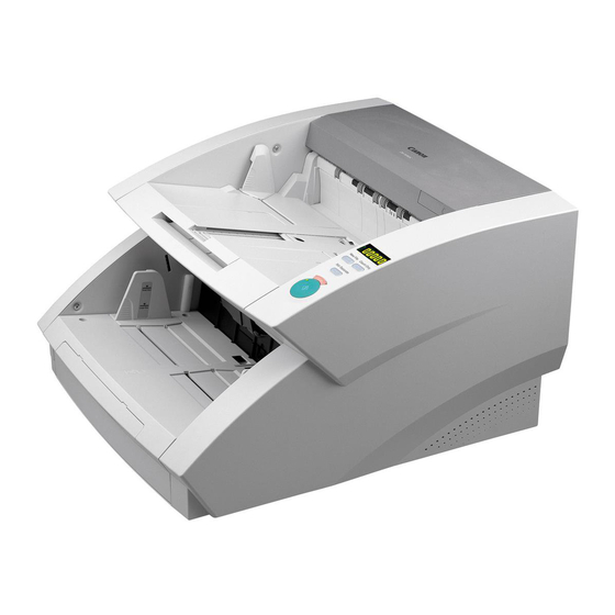
Page 16: Names Of Parts
Document eject tray guide Document guide Upper unit Document tray Imprinter cover Document tray extension / wire Operation panel Document eject tray extension / stopper Fig. 1-401 1 - 8 COPYRIGHT © 2003 CANON ELECTRONICS INC. CANON DR-6080/9080C FIRST EDITION OCT. 2003... - Page 17 Note: Do not block the air vent, otherwise the temperature will rise inside the machine and a fire might result. 3. Connection (Bottom view) USB connector DIP switch SCSI connector Fig. 1-403 1 - 9 COPYRIGHT © 2003 CANON ELECTRONICS INC. CANON DR-6080/9080C FIRST EDITION OCT. 2003...
- Page 18 CHAPTER 1 GENERAL DESCRIPTION 4. Operation Panel Counter display Bypass Mode key Count Only key Stop key New File key Start key Fig. 1-404 1 - 10 COPYRIGHT © 2003 CANON ELECTRONICS INC. CANON DR-6080/9080C FIRST EDITION OCT. 2003...
-
Page 19: V. Explanation Of Operation
Execute the operation. Finish the operation. Quit the application software. Turn the personal computer OFF. Turn the machine OFF. Fig. 1-501 Scanner Settings Fig. 1-502 1 - 11 COPYRIGHT © 2003 CANON ELECTRONICS INC. CANON DR-6080/9080C FIRST EDITION OCT. 2003... - Page 20 CHAPTER 1 GENERAL DESCRIPTION Advanced Settings Save As Fig. 1-505 Fig. 1-503 Filter Settings Fig. 1-504 1 - 12 COPYRIGHT © 2003 CANON ELECTRONICS INC. CANON DR-6080/9080C FIRST EDITION OCT. 2003...
-
Page 21: Power Cord
(A cotton-tipped swab is also acceptable). Be careful not to wipe or touch the electrical contact Feed roller part when wiping the ink. Retard roller Platen roller Feeder roller 1 - 13 COPYRIGHT © 2003 CANON ELECTRONICS INC. CANON DR-6080/9080C FIRST EDITION OCT. 2003... -
Page 23: Vi. Power Supply
IX. LAYOUT OF ELECTRICAL DESCRIPTION OF ELECTRICAL COMPONENTS ........2-49 CIRCUITS..........2-21 LIST OF CONNECTORS, SWITCHES & IMAGE PROCESSING......2-25 LEDS FOR EACH PCB......2-53 POWER SUPPLY ........2-41 COPYRIGHT © 2003 CANON ELECTRONICS INC. CANON DR-6080/9080C REV.0 SEPT. 2003... - Page 24 COPYRIGHT © 2001 CANON ELECTRONICS INC. CANON DR-5060F REJULYY. 2001 PRINTED IN JAPAN (IMPRIME AU JAPON)
-
Page 25: Chapter 2 Functions & Operation
Display Personal computer Printer IF card DR-00900C Application eyoard Mouse software Driver software OS and other software Image Storage Fig. 2-101 2 - 1 COPYRIGHT © 2003 CANON ELECTRONICS INC. CANON DR-6080/9080C REV.0 SEPT. 2003... - Page 26 Controls the feed system and image processor. Power supply assembly Converts AC power to +24 VDC and supplies it to the various PCB assemblies. Table 2-101 2 - 2 COPYRIGHT © 2003 CANON ELECTRONICS INC. CANON DR-6080/9080C REV.0 SEPT. 2003...
- Page 27 Registration clutch signal Upper registration roller Lower registration roller Upper reading roller Lower reading roller Front platen roller Back platen roller Feeder drive roller Fig. 2-103 2 - 3 COPYRIGHT © 2003 CANON ELECTRONICS INC. CANON DR-6080/9080C REV.0 SEPT. 2003...
- Page 28 Shading solenoid (Lower side) Staple LED Document Document Registration Document Retard guide Document tray HP clutch tray motor width sensor sensor motor sensor Fig. 2-104 2 - 4 COPYRIGHT © 2003 CANON ELECTRONICS INC. CANON DR-6080/9080C REV.0 SEPT. 2003...
- Page 29 Note 2: If there is a difference in the timing marked , it indicates the occurrence of skewing. Fig. 2-105 2 - 5 COPYRIGHT © 2003 CANON ELECTRONICS INC. CANON DR-6080/9080C REV.0 SEPT. 2003...
- Page 30 Thus, the document feeding can maintain specific intervals for high speed, medium speed, and slow speed feeding. Table 2-102 2 - 6 COPYRIGHT © 2003 CANON ELECTRONICS INC. CANON DR-6080/9080C REV.0 SEPT. 2003...
-
Page 31: Reading System
This configuration enables the unit Upper reading Front reading unit roller Back platen roller Reading glass Document Reading glass Front platen roller Back reading unit Lower reading roller Fig. 2-201 2 - 7 COPYRIGHT © 2003 CANON ELECTRONICS INC. CANON DR-6080/9080C REV.0 SEPT. 2003... - Page 32 Fig. 2-203 document against the reading glass. (Refer to Fig. 2-203) 2 - 8 COPYRIGHT © 2003 CANON ELECTRONICS INC. CANON DR-6080/9080C REV.0 SEPT. 2003...
- Page 33 Image sensor (CIS) Sensor drive PCB Image sensor Lens array Light guide Light guide Reading glass Document LEDs (R/G/B) LEDs (R/G/B) Fig. 2-204 2 - 9 COPYRIGHT © 2003 CANON ELECTRONICS INC. CANON DR-6080/9080C REV.0 SEPT. 2003...
- Page 34 Shading solenoid drive PCB of the reading unit. (Upper side) Upper Back platen shading plate roller Back reading unit Fig. 2-205 2 - 10 COPYRIGHT © 2003 CANON ELECTRONICS INC. CANON DR-6080/9080C REV.0 SEPT. 2003...
-
Page 35: Feed System
Feed errors (jams) can be detected by the registration sensors (front & back). • Special feed mode Checks the feed condition of the machine whithout using the personal computer. 2 - 11 COPYRIGHT © 2003 CANON ELECTRONICS INC. CANON DR-6080/9080C REV.0 SEPT. 2003... - Page 36 Front reading unit Front platen roller Back reading unit Upper reading roller Document tray Lower reading roller Ultrasonic (receiving) sensor Back platen roller Ultrasonic (transmitting) sensor Fig. 2-301 2 - 12 COPYRIGHT © 2003 CANON ELECTRONICS INC. CANON DR-6080/9080C REV.0 SEPT. 2003...
- Page 37 Front registration L sensor (PS7) Front registration R sensor (PS9) Left-end sensor (PS6) Back registration sensor (PS8) Right-end sensor (PS10) Staple LED Staple photo-sensor Fig. 2-303 2 - 13 COPYRIGHT © 2003 CANON ELECTRONICS INC. CANON DR-6080/9080C REV.0 SEPT. 2003...
- Page 38 Pick-up sensor Pick-up roller Document Document sensor Document guide Document tray Light blocking plate Box unit Document tray Document tray HP sensor motor Fig. 2-304 Fig. 2-305 2 - 14 COPYRIGHT © 2003 CANON ELECTRONICS INC. CANON DR-6080/9080C REV.0 SEPT. 2003...
- Page 39 At the same time, the raising of the document tray is stopped. After that, the pick-up motor and feed motor are started simultaneously to feed the document. 2 - 15 COPYRIGHT © 2003 CANON ELECTRONICS INC. CANON DR-6080/9080C REV.0 SEPT. 2003...
- Page 40 Manual Feed is selected on the computer, the driving of the feed roller is turned OFF and the retard roller begins to rotate forward direction, invalidating separation function. 2 - 16 COPYRIGHT © 2003 CANON ELECTRONICS INC. CANON DR-6080/9080C REV.0 SEPT. 2003...
- Page 41 Document curl must be 3 mm or less in height and the documents cannot be creased. It is possible to change the level of detection accuracy with the user mode. 2 - 17 COPYRIGHT © 2003 CANON ELECTRONICS INC. CANON DR-6080/9080C REV.0 SEPT. 2003...
- Page 42 Turns document run into the registration roller so that Document this way the skew is corrected. (Refer to Fig. 2-310-a) Registration roller (rotating) Fig. 2-310 2 - 18 COPYRIGHT © 2003 CANON ELECTRONICS INC. CANON DR-6080/9080C REV.0 SEPT. 2003...
- Page 43 50 mm, the double feed may not be detected. Feed direction Ultrasonic (transmitting) Fig. 2-311 sensor Document feed direction Ultrasonic (receiving) sensor Fig. 2-312 2 - 19 COPYRIGHT © 2003 CANON ELECTRONICS INC. CANON DR-6080/9080C REV.0 SEPT. 2003...
- Page 44 Color 200DPI Color 300DPI Color 400DPI Color 600DPI The figures 1-3 above indicate the numbers of the DIP switch used to set the SCSI ID. Table 2-301 2 - 20 COPYRIGHT © 2003 CANON ELECTRONICS INC. CANON DR-6080/9080C REV.0 SEPT. 2003...
-
Page 45: Description Of Electrical Circuits
CHAPTER 2 FUNCTIONS & OPERATION Fig. 2-401 shows a block diagram of the IV. DESCRIPTION OF main CPU PCB for the DR-9080C and the DR-6080. The only difference between the ELECTRICAL DR-9080C and the DR-6080 is the number of 256M bit SDRAM chips. Table 2-401 lists the CIRCUITS function of each IC shown in the block diagram. - Page 46 12.0V generation Q150,151 Energy save mode switch Note: The DR-9080C has 12 memory chips for image data (SDRAM) numbered from IC104 to IC115, while the DR-6080 has 6 of them numbered from IC104 to IC109. Table 2-401 2 - 22 COPYRIGHT ©...
- Page 47 Ultrasonic sensor PCB Ultrasonic (receiving) sensor USS1 Mechanical CNT1 counter Imprinter Left-end sensor PCB Upper unit door sensor Left-end sensor Right-end sensor PCB Right-end sensor PS10 Fig. 2-402 2 - 23 COPYRIGHT © 2003 CANON ELECTRONICS INC. CANON DR-6080/9080C REV.0 SEPT. 2003...
- Page 48 HP sensor Staple Staple LED Staple LED photo-sensor Registration clutch Motor drive Retard motor circuit Motor drive Document tray circuit motor Shading solenoid (Lower side) Fig. 2-403 2 - 24 COPYRIGHT © 2003 CANON ELECTRONICS INC. CANON DR-6080/9080C REV.0 SEPT. 2003...
-
Page 49: Image Processing
300 dpi or less (300, 240, 200, 150, 100), the optical resolution of the unit is set to 300 2 - 25 COPYRIGHT © 2003 CANON ELECTRONICS INC. CANON DR-6080/9080C REV.0 SEPT. 2003... - Page 50 The image data are stored in the SDRAM, and accessed via the SDRAM_I/F (Interface). Image processor 2 handles brightness adjustment, contrast adjustment, and gamma correction. 2 - 26 COPYRIGHT © 2003 CANON ELECTRONICS INC. CANON DR-6080/9080C REV.0 SEPT. 2003...
- Page 51 Data output R1 R2 G1 G2 B1 B2 b. RGB rearrangement R1 G1 B1 R2 G2 B2 1st pixel 2nd pixel Nth pixel Fig. 2-502 2 - 27 COPYRIGHT © 2003 CANON ELECTRONICS INC. CANON DR-6080/9080C REV.0 SEPT. 2003...
- Page 52 600 dpi, and when 240 dpi or less is selected, it is converted from 300 dpi. 9 10 11 300 dpi standard clock 300 dpi image data 200 dpi operating clock 200 dpi image data Fig. 2-503 2 - 28 COPYRIGHT © 2003 CANON ELECTRONICS INC. CANON DR-6080/9080C REV.0 SEPT. 2003...
- Page 53 Sample point 300dpi, Color Feed speed (229mm/sec) 150dpi, Color Feed speed (457mm/sec) Fig. 2-504a 300dpi, Binary Feed speed (686mm/sec) 150dpi, Binary Feed speed (686mm/sec) Fig. 2-504b 2 - 29 COPYRIGHT © 2003 CANON ELECTRONICS INC. CANON DR-6080/9080C REV.0 SEPT. 2003...
- Page 54 • The data are calculated according to the selected resolution. An example of conversion from 300 dpi to 150 dpi is as follows: (A+B)/2 (C+D)/2 (E+F)/2 · · · 2 - 30 COPYRIGHT © 2003 CANON ELECTRONICS INC. CANON DR-6080/9080C REV.0 SEPT. 2003...
- Page 55 6th line 150 x 150 dpi 1st line (A+B)/2 (C+D)/2 (E+F)/2 (G+H)/2 2nd line (A+B)/2 (C+D)/2 (E+F)/2 (G+H)/2 3rd line (A+B)/2 (C+D)/2 (E+F)/2 (G+H)/2 Fig. 2-505 2 - 31 COPYRIGHT © 2003 CANON ELECTRONICS INC. CANON DR-6080/9080C REV.0 SEPT. 2003...
- Page 56 Before conversion automatic brightness adjustment in Black & White mode, refer to the “Binarizing" section. Fig. 2-507 White (255) Black White (255) Before conversion Fig. 2-506 2 - 32 COPYRIGHT © 2003 CANON ELECTRONICS INC. CANON DR-6080/9080C REV.0 SEPT. 2003...
- Page 57 In this case, the brightness and contrast adjustments become invalid. White (255) Black White (255) Before conversion Fig. 2-508 2 - 33 COPYRIGHT © 2003 CANON ELECTRONICS INC. CANON DR-6080/9080C REV.0 SEPT. 2003...
- Page 58 (B) of the conversion table. Target picture element (density a) Output Target picture element (density a) : 1~64 Conversion table Main-scanning direction Fig. 2-510 2 - 34 COPYRIGHT © 2003 CANON ELECTRONICS INC. CANON DR-6080/9080C REV.0 SEPT. 2003...
- Page 59 “slice level” (or threshold value). 1 picture element White 255 White Slice level Black Black 0 Document Output Fig. 2-511 2 - 35 COPYRIGHT © 2003 CANON ELECTRONICS INC. CANON DR-6080/9080C REV.0 SEPT. 2003...
- Page 60 Output data Input data Error+6=(9-3)-0 (9-3)=6<8 → "0" Input Output Error of first row of Line 1 Error of first row of Line 1 Fig. 2-513 2 - 36 COPYRIGHT © 2003 CANON ELECTRONICS INC. CANON DR-6080/9080C REV.0 SEPT. 2003...
- Page 61 Fig. 2-515 shows a comparison of binarizing with error diffusion processing, and binarizing without error diffusion processing (simple binarizing). Digital signal output Without error diffusion processing With error diffusion processing Fig. 2-515 2 - 37 COPYRIGHT © 2003 CANON ELECTRONICS INC. CANON DR-6080/9080C REV.0 SEPT. 2003...
- Page 62 This process is known as ABC (Auto Back-ground Control). Output White ABC selected (255) Document ABC selected Slice level not selected Black White ABC not selected (255) Before conversion Fig. 2-516 2 - 38 COPYRIGHT © 2003 CANON ELECTRONICS INC. CANON DR-6080/9080C REV.0 SEPT. 2003...
- Page 63 • Size detection, etc. The main types of image processing are described below. For others, refer to the driver software "Help". Slice level Black White Brightness level Fig. 2-517 2 - 39 COPYRIGHT © 2003 CANON ELECTRONICS INC. CANON DR-6080/9080C REV.0 SEPT. 2003...
- Page 64 Black frame Angle Output image data Image data after Image data (set size image data) skew correction Fig. 2-518 2 - 40 COPYRIGHT © 2003 CANON ELECTRONICS INC. CANON DR-6080/9080C REV.0 SEPT. 2003...
-
Page 65: Power Supply
3.3V 12.0V 5.0U 5.0V Switching regulator IC 1.8V (IC155) 24.0V 24.0U 3.3V (IC131) (Q151) 5.0V (IC116) 12.0V (IC156) (Q150) +24VD (DC power supply PCB) Fig. 2-602 2 - 41 COPYRIGHT © 2003 CANON ELECTRONICS INC. CANON DR-6080/9080C REV.0 SEPT. 2003... -
Page 66: Power Saving Mode
If an excessive current flows in the + 24 VDC supplied to the main motor, the fuse blows and stops the power supply to the main motor. 2 - 42 COPYRIGHT © 2003 CANON ELECTRONICS INC. CANON DR-6080/9080C REV.0 SEPT. 2003... -
Page 67: Interface
The SCSI bus is made up of data signals (1 byte + parity bit = 9 signals) and control signals (9 signals) for a total of 18 lines. Fig. 2-701 2 - 43 COPYRIGHT © 2003 CANON ELECTRONICS INC. CANON DR-6080/9080C REV.0 SEPT. 2003... - Page 68 Vcc (+5V) Differential signal(-) Differential signal(+) Ground Table 2-702 USB is also referred to as a differential interface, and uses 2 signal lines for a single signal. 2 - 44 COPYRIGHT © 2003 CANON ELECTRONICS INC. CANON DR-6080/9080C REV.0 SEPT. 2003...
-
Page 69: Power Supply
12 x 12 dots (Regular)/ 12 x 8 dots (small) Orientation / 90 / 180 / 270 Power supply Supplied from DR-6080/9080C Consumables Ink cartridge Table. 2-801 2 - 45 COPYRIGHT © 2003 CANON ELECTRONICS INC. CANON DR-6080/9080C REV.0 SEPT. 2003... - Page 70 In the center, within 26mm of either side Note: The area size indicates the size of the date area. 100mm 53mm 24mm/26mm 24mm/26mm Rear Table. 2-802-a 2 - 46 COPYRIGHT © 2003 CANON ELECTRONICS INC. CANON DR-6080/9080C REV.0 SEPT. 2003...
- Page 71 5 years of use or 6 million sheets scanned, whichever product comes first. Note: Guide for the time to replace the ink roller is 0.2 million sheets. Table. 2-802-b 2 - 47 COPYRIGHT © 2003 CANON ELECTRONICS INC. CANON DR-6080/9080C REV.0 SEPT. 2003...
- Page 72 The barcodes supported by this module are EAN/JAN, CODABAR, CODE39, ITF, CODE128, UPC-A, and UPC-E. The barcode module can be installed by the user. 2 - 48 COPYRIGHT © 2003 CANON ELECTRONICS INC. CANON DR-6080/9080C REV.0 SEPT. 2003...
-
Page 73: Layout Of Electrical Components
CHAPTER 2 FUNCTIONS & OPERATION IX. LAYOUT OF ELECTRICAL COMPONENTS 1. Switches and Sensors USS1 USS2 GRID1 PS10 GRID2 Fig. 2-901 2 - 49 COPYRIGHT © 2003 CANON ELECTRONICS INC. CANON DR-6080/9080C REV.0 SEPT. 2003... - Page 74 USS2 sensor Staple LED GRID1 Detecting the jumping up of stapled documents. Staple photo-sensor GRID2 Document guide width Detecting the width of documents. sensor Table 2-901 2 - 50 COPYRIGHT © 2003 CANON ELECTRONICS INC. CANON DR-6080/9080C REV.0 SEPT. 2003...
- Page 75 Shading solenoid (Upper Activating the shading plate of the back reading side) unit. Shading solenoid (Lower Activating the shading plate of the front reading side) unit. Table 2-902 2 - 51 COPYRIGHT © 2003 CANON ELECTRONICS INC. CANON DR-6080/9080C REV.0 SEPT. 2003...
- Page 76 Reading the back side of documents. DC power supply PCB Supplying DC power. Table 2-903 Note: For information on the PCBs related to sensors, refer to “1. Switches and Sensors”. 2 - 52 COPYRIGHT © 2003 CANON ELECTRONICS INC. CANON DR-6080/9080C REV.0 SEPT. 2003...
-
Page 77: List Of Connectors, Switches & Leds For Each Pcb
1. Main CPU PCB (MAIN_DCON) J140 J136 J137 J139 J135 J132 J131 LED104 LED106 LED101 J117 SW102 J124 J114 J124 J121 J105 Fig. 2-1001 2 - 53 COPYRIGHT © 2003 CANON ELECTRONICS INC. CANON DR-6080/9080C REV.0 SEPT. 2003... - Page 78 ID 4 ID 5 ID 6 ID 7 1 2 3 4 Note: The switch settings should only be changed when the power is OFF. Table 2-1002 2 - 54 COPYRIGHT © 2003 CANON ELECTRONICS INC. CANON DR-6080/9080C REV.0 SEPT. 2003...
- Page 79 CHAPTER 2 FUNCTIONS & OPERATION 2. Pick-up Control PCB (80_SUB) LED1 J401 J409 J404 J406 J413 Fig. 2-1002 LED No. Indication LED1 Flashing when working normally Table 2-1003 2 - 55 COPYRIGHT © 2003 CANON ELECTRONICS INC. CANON DR-6080/9080C REV.0 SEPT. 2003...
- Page 80 CHAPTER 2 FUNCTIONS & OPERATION 3. Document Tray PCB (10_SUB) J504 LED1 J503 J506 J509 J505 J508 J507 Fig. 2-1003 LED No. Indication LED1 Flashing when working normally Table 2-1004 2 - 56 COPYRIGHT © 2003 CANON ELECTRONICS INC. CANON DR-6080/9080C REV.0 SEPT. 2003...
-
Page 81: Iii. Feed System (Rollers)
CHAPTER 3 DISASSEMBLY & REASSEMBLY EXTERNAL ASSEMBLY ......3-1 READING SECTION......3-35 II . DRIVE SYSTEM (MOTORS)....3-12 ELECTRICAL PARTS ......3-38 III. FEED SYSTEM (ROLLERS) ....3-22 COPYRIGHT © 2003 CANON ELECTRONICS INC. CANON DR-6080/9080C FIRST EDITION OCT. 2003... - Page 82 COPYRIGHT © 2001 CANON ELECTRONICS INC. CANON DR-5060F REJULYY. 2001 PRINTED IN JAPAN (IMPRIME AU JAPON)
-
Page 83: External Assembly
Right cover Left cover Upper delivery cover Front delivery cover Document tray Document guide Document tray front cover Lower front cover Upper unit Fig. 3-101 3 - 1 COPYRIGHT © 2003 CANON ELECTRONICS INC. CANON DR-6080/9080C FIRST EDITION OCT. 2003... -
Page 84: Top Cover
• Insert the positioning boss of the top cover into the hole in the main body. Upper unit Screw Fig. 3-106 Boss Blind plate A/B Fig. 3-104 3 - 2 COPYRIGHT © 2003 CANON ELECTRONICS INC. CANON DR-6080/9080C FIRST EDITION OCT. 2003... - Page 85 Connector Screw Operation panel PCB Right cover Screw A Screw B Hook Right cover assembly Fig. 3-108 Fig. 3-107 3 - 3 COPYRIGHT © 2003 CANON ELECTRONICS INC. CANON DR-6080/9080C FIRST EDITION OCT. 2003...
-
Page 86: Left Cover
, and then detach the front side while lifting it upward. IP cover Screw Upper delivery cover assembly Fig. 3-112 Screw A Screw B Hook Left cover Fig. 3-110 3 - 4 COPYRIGHT © 2003 CANON ELECTRONICS INC. CANON DR-6080/9080C FIRST EDITION OCT. 2003... - Page 87 Release the boss on each side by bending the IP cover to separate it from the upper delivery cover IP cover Boss Upper delivery cover Fig. 3-114 3 - 5 COPYRIGHT © 2003 CANON ELECTRONICS INC. CANON DR-6080/9080C FIRST EDITION OCT. 2003...
-
Page 88: Document Guide
Lift the document tray assembly , release the connector , and detach the document tray assembly and document tray extension Document tray assembly Connector Document tray extension Fig. 3-117 3 - 6 COPYRIGHT © 2003 CANON ELECTRONICS INC. CANON DR-6080/9080C FIRST EDITION OCT. 2003... - Page 89 Precautions during assembly • Position the document guide symmetrically during assembly. Document tray driving unit Connector Document guide Fig. 3-122 Fig. 3-120 3 - 7 COPYRIGHT © 2003 CANON ELECTRONICS INC. CANON DR-6080/9080C FIRST EDITION OCT. 2003...
- Page 90 • Since the tips of the screws that mount the document tray driving unit will protrude, use the screws with round-shaped tips to prevent injuries. 3 - 8 COPYRIGHT © 2003 CANON ELECTRONICS INC. CANON DR-6080/9080C FIRST EDITION OCT. 2003...
-
Page 91: Upper Unit
Note: Be careful not to drop the parallel pin. Screw Lower front cover Fig. 3-125 Screw Leaf spring Screw Damper Tensioner Screw E-ring Pulley Belt Screw Pivot Fig. 3-126 3 - 9 COPYRIGHT © 2003 CANON ELECTRONICS INC. CANON DR-6080/9080C FIRST EDITION OCT. 2003... - Page 92 Note: Detach the upper unit while holding it to prevent it from falling. Cable Clamp Connector Fig. 3-127 Screw Stopper Screw Damper Screw Pivot Cable Upper unit Fig. 3-128 3 - 10 COPYRIGHT © 2003 CANON ELECTRONICS INC. CANON DR-6080/9080C FIRST EDITION OCT. 2003...
- Page 93 • Install the leaf spring and the stopper at the end of the assembly, with the upper unit closed. 3 - 11 COPYRIGHT © 2003 CANON ELECTRONICS INC. CANON DR-6080/9080C FIRST EDITION OCT. 2003...
-
Page 94: Drive System (Motors)
• Fix the main motor assembly position so that the belt does not miss the sprockets. However, the fixing should not be tightened too much. Screw Belt Main motor assembly Fig. 3-201 3 - 12 COPYRIGHT © 2003 CANON ELECTRONICS INC. CANON DR-6080/9080C FIRST EDITION OCT. 2003... - Page 95 Screw Screw Gear unit Fig. 3-204 Boss Slotted hole Reinforcing plate Fig. 3-203 3 - 13 COPYRIGHT © 2003 CANON ELECTRONICS INC. CANON DR-6080/9080C FIRST EDITION OCT. 2003...
- Page 96 "Document tray front cover". Screw A Screw B • Make sure that the reinforcing plate is lowered to the bottom before the installation. Fig. 3-207 Fig. 3-206 3 - 14 COPYRIGHT © 2003 CANON ELECTRONICS INC. CANON DR-6080/9080C FIRST EDITION OCT. 2003...
- Page 97 Connector Screw Screw Pick-up assembly Feed motor assembly Fig. 3-208 Fig. 3-210 Remove two screws and dismount the pick-up motor Screw Pick-up motor Fig. 3-209 3 - 15 COPYRIGHT © 2003 CANON ELECTRONICS INC. CANON DR-6080/9080C FIRST EDITION OCT. 2003...
- Page 98 Lower entry guide plate cover up if the one-way pulley is installed Screw backwards when replacing the feed motor Lower entry guide plate belt. Fig. 3-212 3 - 16 COPYRIGHT © 2003 CANON ELECTRONICS INC. CANON DR-6080/9080C FIRST EDITION OCT. 2003...
- Page 99 . Install the projections in the matching holes and insert the arm into the hooks until it clicks. Screw Retard motor Fig. 3-214 Round Oval Fig. 3-216 3 - 17 COPYRIGHT © 2003 CANON ELECTRONICS INC. CANON DR-6080/9080C FIRST EDITION OCT. 2003...
- Page 100 Fig. 3-219 Connector Screw Fig. 3-217 Lift the end of the shaft to pull it off and detach the solenoid Shaft Solenoid Fig. 3-218 3 - 18 COPYRIGHT © 2003 CANON ELECTRONICS INC. CANON DR-6080/9080C FIRST EDITION OCT. 2003...
- Page 101 Turn over the platen unit, remove two screws Screw Belt , and detach the solenoid assembly E-ring Connector Clutch Fig. 3-220 Screw Solenoid assembly Fig. 3-222 3 - 19 COPYRIGHT © 2003 CANON ELECTRONICS INC. CANON DR-6080/9080C FIRST EDITION OCT. 2003...
- Page 102 , and detach the solenoid body Remove screws (with round-shaped tips) and detach the plunger assembly Fig. 3-224 Connector Screw A Solenoid body Screw B Plunger assembly Fig. 3-226 3 - 20 COPYRIGHT © 2003 CANON ELECTRONICS INC. CANON DR-6080/9080C FIRST EDITION OCT. 2003...
- Page 103 1 and the feed guide plate 2. Refer to the section entitled "Feeder follower roller". Mount plate Shading plate Platen roller Gear teeth Spacer Fig. 3-227 3 - 21 COPYRIGHT © 2003 CANON ELECTRONICS INC. CANON DR-6080/9080C FIRST EDITION OCT. 2003...
-
Page 104: Feed System (Rollers)
Fig. 3-304 Roller holder Pick-up roller Fig. 3-302 Precautions during assembly • Close the roller holder or the roller cover completely until it is hooked. 3 - 22 COPYRIGHT © 2003 CANON ELECTRONICS INC. CANON DR-6080/9080C FIRST EDITION OCT. 2003... - Page 105 Retard roller Fig. 3-307 Precautions during assembly • Fit the notch on the right side of the roller to the pin on the main body side. 3 - 23 COPYRIGHT © 2003 CANON ELECTRONICS INC. CANON DR-6080/9080C FIRST EDITION OCT. 2003...
- Page 106 Fig. 3-309 Upper registration roller guide Fig. 3-308 Remove two E-rings (one on each side) and detach the stopper assembly E-ring Stopper assembly Fig. 3-310 3 - 24 COPYRIGHT © 2003 CANON ELECTRONICS INC. CANON DR-6080/9080C FIRST EDITION OCT. 2003...
- Page 107 Claw of the stopper Upper reading roller assembly Fig. 3-313 Detach the stopper assembly. Refer to the section entitled "Upper registration roller". 3 - 25 COPYRIGHT © 2003 CANON ELECTRONICS INC. CANON DR-6080/9080C FIRST EDITION OCT. 2003...
- Page 108 Upper reading roller guide Screw B Feed guide plate 1 Precautions during assembly • Fix feed guide plate 1 by matching three fits on the back. Fig. 3-314 3 - 26 COPYRIGHT © 2003 CANON ELECTRONICS INC. CANON DR-6080/9080C FIRST EDITION OCT. 2003...
- Page 109 Detach the stopper assembly. Refer to the section entitled "Upper registration roller". Screw Feed guide plate 1 Feed guide plate 2 Feed guide plate 3 Fig. 3-316 3 - 27 COPYRIGHT © 2003 CANON ELECTRONICS INC. CANON DR-6080/9080C FIRST EDITION OCT. 2003...
- Page 110 Delivery follower roller assembly Shaft Roller Feed guide plate 1 Upper-right projection Coil spring Upper-left projection Convex part Groove Fig. 3-319 Fig. 3-318 3 - 28 COPYRIGHT © 2003 CANON ELECTRONICS INC. CANON DR-6080/9080C FIRST EDITION OCT. 2003...
- Page 111 (one on each side), and lower the lever to detach the lower registration roller Lever Lower registration roller Fig. 3-321 E-ring Bearing Lever Lower registration roller Fig. 3-320 3 - 29 COPYRIGHT © 2003 CANON ELECTRONICS INC. CANON DR-6080/9080C FIRST EDITION OCT. 2003...
- Page 112 Unhook the connector Screw E-ring Bearing Platen unit Back platen roller Spacer Connector Gear Fig. 3-322 Fig. 3-323 3 - 30 COPYRIGHT © 2003 CANON ELECTRONICS INC. CANON DR-6080/9080C FIRST EDITION OCT. 2003...
- Page 113 Precautions during assembly • Be sure to install the pulley with the flange correctly oriented. The pulley for the lower reading roller is flanged on the inside. 3 - 31 COPYRIGHT © 2003 CANON ELECTRONICS INC. CANON DR-6080/9080C FIRST EDITION OCT. 2003...
- Page 114 Note: Feeder drive rollers B and C are the same parts. Belt E-ring E-ring Pulley Pulley Bearing Bearing Feeder drive roller A Feeder drive rollers B/C Fig. 3-326 Fig. 3-327 3 - 32 COPYRIGHT © 2003 CANON ELECTRONICS INC. CANON DR-6080/9080C FIRST EDITION OCT. 2003...
- Page 115 • Do not allow any slack in the belt. Adjust the Delivery drive roller tension so that the belt does not miss the Fig. 3-328 sprockets and the tension is not tightened too much. 3 - 33 COPYRIGHT © 2003 CANON ELECTRONICS INC. CANON DR-6080/9080C FIRST EDITION OCT. 2003...
- Page 116 • After hanging the belt on the pulley, fix the screw of the tension plate. The tension of the belt can be adjusted with the coil spring attached to the tension plate. 3 - 34 COPYRIGHT © 2003 CANON ELECTRONICS INC. CANON DR-6080/9080C FIRST EDITION OCT. 2003...
- Page 117 • The back registration sensor PCB is mounted in Upper registration roller guide the front reading unit, Detach the PCB as Upper reading roller guide necessary. Stopper Front reading unit Fig. 3-401 3 - 35 COPYRIGHT © 2003 CANON ELECTRONICS INC. CANON DR-6080/9080C FIRST EDITION OCT. 2003...
- Page 118 • Clean the reading glass. Cable clamp Back reading unit Fig. 3-403 Unhook three connectors and detach the back reading unit Fig. 3-404 Connector Back reading unit 3 - 36 COPYRIGHT © 2003 CANON ELECTRONICS INC. CANON DR-6080/9080C FIRST EDITION OCT. 2003...
- Page 119 • Clean the shading plate. solenoid side, and also adjust the position of the solenoid. • Clean the shading plate. 3 - 37 COPYRIGHT © 2003 CANON ELECTRONICS INC. CANON DR-6080/9080C FIRST EDITION OCT. 2003...
- Page 120 • Make sure that every cable is connected and securely inserted. • Do not pull in the cables. Fix them using cable Main CPU PCB clamps. Screw Fig. 3-501 3 - 38 COPYRIGHT © 2003 CANON ELECTRONICS INC. CANON DR-6080/9080C FIRST EDITION OCT. 2003...
- Page 121 • Do not pull in the cables. Fix them using cable clamps. Document tray control PCB Connector Fig. 3-505 3 - 39 COPYRIGHT © 2003 CANON ELECTRONICS INC. CANON DR-6080/9080C FIRST EDITION OCT. 2003...
- Page 122 • Since the tips of the three screws that fix the panel will protrude, use the screws with round-shaped tips to prevent injuries. DC power supply PCB Connector Fig. 3-507 3 - 40 COPYRIGHT © 2003 CANON ELECTRONICS INC. CANON DR-6080/9080C FIRST EDITION OCT. 2003...
- Page 123 , and then detach the exhaust fan PCB (with metal plates) Connector Screw Exhaust fan Fig. 3-509 Connector Screw Ultrasonic sensor PCB (with metal plates) Fig. 3-510 3 - 41 COPYRIGHT © 2003 CANON ELECTRONICS INC. CANON DR-6080/9080C FIRST EDITION OCT. 2003...
- Page 124 Cable Screw Fig. 3-511 Positioning mark Fig. 3-513 3 - 42 COPYRIGHT © 2003 CANON ELECTRONICS INC. CANON DR-6080/9080C FIRST EDITION OCT. 2003...
- Page 125 Remove the gear . Additionally, remove one screw and detach the document guide and the rack by sliding them out. Gear Screw Document guide Rack Fig. 3-515 3 - 43 COPYRIGHT © 2003 CANON ELECTRONICS INC. CANON DR-6080/9080C FIRST EDITION OCT. 2003...
- Page 126 Document guide width sensor Spacer Fig. 3-517 • Position the document guide symmetrically during assembly. After reassembly, check that the document guide moves smoothly. Document guide Fig. 3-518 3 - 44 COPYRIGHT © 2003 CANON ELECTRONICS INC. CANON DR-6080/9080C FIRST EDITION OCT. 2003...
- Page 127 P R O C E D U R E ..........4-10 LIS T ............4-19 M EC H AN IC AL C O U NT ER IN STALLATIO N PR O C ED U R E ..........4-14 COPYRIGHT © 2003 CANON ELECTRONICS INC. CANON DR-6080/9080C FIRST EDITION OCT. 2003...
- Page 128 COPYRIGHT © 2001 CANON ELECTRONICS INC. CANON DR-5060F REVJULY. 2001 PRINTED IN JAPAN (IMPRIME AU JAPON)
-
Page 129: Chapter 4 Installation & Maintenance
In particular, do not install the machine near 660 mm or more water faucets, humidifiers, hot water heaters, and refrigerators. Fig. 4-101 4 - 1 COPYRIGHT © 2003 CANON ELECTRONICS INC. CANON DR-6080/9080C FIRST EDITION OCT. 2003... -
Page 130: Unpacking & Installation
600 (W) x 700 (D) x 450 (H) mm. Main body Power cord Grounding wire (100V model only) Quick reference guide Setup disk (CR-ROM) User's manual Warranty card (100V and 120V models only) 4 - 2 COPYRIGHT © 2003 CANON ELECTRONICS INC. CANON DR-6080/9080C FIRST EDITION OCT. 2003... - Page 131 Protective pad Connect the power cord. In the case of the 100V model, connect the grounding wire too. 4 - 3 COPYRIGHT © 2003 CANON ELECTRONICS INC. CANON DR-6080/9080C FIRST EDITION OCT. 2003...
- Page 132 Install the driver and application software on the personal computer. For details, refer to the user's manual. Check if the machine operates normally. For details, refer to the user's manual. 4 - 4 COPYRIGHT © 2003 CANON ELECTRONICS INC. CANON DR-6080/9080C FIRST EDITION OCT. 2003...
-
Page 133: Imprinter Mounting Procedure
Place the inserted tip into the hole on the right side of the machine. Note: Insert the unit vertically at the left side of the machine. 4 - 5 COPYRIGHT © 2003 CANON ELECTRONICS INC. CANON DR-6080/9080C FIRST EDITION OCT. 2003... - Page 134 Short Insert the longer convex tip of the IP shaft into the hole inside the right side of the main body. 4 - 6 COPYRIGHT © 2003 CANON ELECTRONICS INC. CANON DR-6080/9080C FIRST EDITION OCT. 2003...
- Page 135 Insert the snap band attached to the cable assembly of the IP carriage into the hole located at the center of the main body upper frame. 4 - 7 COPYRIGHT © 2003 CANON ELECTRONICS INC. CANON DR-6080/9080C FIRST EDITION OCT. 2003...
- Page 136 Install the upper delivery cover assembly. Note: The upper delivery cover assembly should be installed with the imprinter cover opened. Attach the right and left covers, and the rear cover. 4 - 8 COPYRIGHT © 2003 CANON ELECTRONICS INC. CANON DR-6080/9080C FIRST EDITION OCT. 2003...
- Page 137 The ink cartridges are sold separately. Use the products made by Hewlett-Packard Company, with part numbers as follows: C6602R (Red), C6602G (Green) C6602B (Blue) Check that the imprinter operates normally. 4 - 9 COPYRIGHT © 2003 CANON ELECTRONICS INC. CANON DR-6080/9080C FIRST EDITION OCT. 2003...
-
Page 138: Endorser Ed600 Mounting Procedure
Leaf springs: 2 pieces Screws (stepped type): 2 pieces Screw (BH, M3x4): 1 piece User’s manual Note: The ink roller and stamping plate are sold separately. 4 - 10 COPYRIGHT © 2003 CANON ELECTRONICS INC. CANON DR-6080/9080C FIRST EDITION OCT. 2003... - Page 139 Refer to “CHAPTER 3: DISASSEMBLY & REASSEMBLY." Take the blind plate (attached at three places) off of the top cover. Install the endorser cable assembly (with two stepped screws). 4 - 11 COPYRIGHT © 2003 CANON ELECTRONICS INC. CANON DR-6080/9080C FIRST EDITION OCT. 2003...
- Page 140 J110 of the main CPU PCB (MAIN_DCON). Install a leaf spring at each side (with a screw). Attach the top and rear covers. 4 - 12 COPYRIGHT © 2003 CANON ELECTRONICS INC. CANON DR-6080/9080C FIRST EDITION OCT. 2003...
- Page 141 Check that the unit operates normally. For details on how to operate it, refer to the user’s manuals for the DR-6080/9080C and ED600. 4 - 13 COPYRIGHT © 2003 CANON ELECTRONICS INC. CANON DR-6080/9080C FIRST EDITION OCT. 2003...
-
Page 142: Mechanical Counter Installation Procedure
Make sure that all the mounting parts are ready. Mechanical counter unit Screw (M3x6) Remove the upper delivery assembly. Note: Refer to “CHAPTER 3: DISASSEMBLY & REASSEMBLY." Install the mechanical counter unit. 4 - 14 COPYRIGHT © 2003 CANON ELECTRONICS INC. CANON DR-6080/9080C FIRST EDITION OCT. 2003... - Page 143 Check that the unit operates normally. Note: Feed documents to check that the number on the counter is increased by the number of fed documents. 4 - 15 COPYRIGHT © 2003 CANON ELECTRONICS INC. CANON DR-6080/9080C FIRST EDITION OCT. 2003...
- Page 144 They are replaced by the user or service technician. 3. Periodically replaced parts are usually defined as products for service and replaced by the service technician. 4 - 16 COPYRIGHT © 2003 CANON ELECTRONICS INC. CANON DR-6080/9080C FIRST EDITION OCT. 2003...
- Page 145 Press the “Reset” button to reset the counter counter. the method is shown below. to “0”. Fig 4-603 • This replacement message is not available for WindowsNT. 4 - 17 COPYRIGHT © 2003 CANON ELECTRONICS INC. CANON DR-6080/9080C FIRST EDITION OCT. 2003...
-
Page 146: Consumable Parts And Consumables
Note 2: For the ink cartridges, use the products made by Hewlett-Packard Company, with part numbers as follows: C6602R (Red), C6602G (Green) C6602B (Blue) 4 - 18 COPYRIGHT © 2003 CANON ELECTRONICS INC. CANON DR-6080/9080C FIRST EDITION OCT. 2003... -
Page 147: Periodic Maintenance Service List
Refer to the user’s manual packaged with the imprinter. Note 4: Because dust on the power cord connectors may cause electrical leakage, clean them as necessary. 4 - 19 COPYRIGHT © 2003 CANON ELECTRONICS INC. CANON DR-6080/9080C FIRST EDITION OCT. 2003... - Page 148 Clean the inside of the machine as necessary. This cleaning must be performed by a service technician, not the user. 4 - 20 COPYRIGHT © 2003 CANON ELECTRONICS INC. CANON DR-6080/9080C FIRST EDITION OCT. 2003...
-
Page 149: Troubleshooting
O P E R ATIO N T R O U B LE S H O O TIN G ..5-24 REMOVING DOCUMENT JAMS .... 5-5 III. SERVICE MODES........5-7 VII. FEED TROUBLESHOOTING ....5-26 USER MODES ........5-20 VIII. AFTER REPLACING PARTS....5-27 COPYRIGHT © 2003 CANON ELECTRONICS INC. CANON DR-6080/9080C FIRST EDITION OCT. 2003... - Page 150 COPYRIGHT © 2001 CANON ELECTRONICS INC. CANON DR-5060F REVJULY. 2001 PRINTED IN JAPAN (IMPRIME AU JAPON)
-
Page 151: Chapter 5 Troubleshooting
Endorser cover and upper unit are open. completely. Endorser cover and imprinter cover are open. Endorser cover, imprinter cover, and upper unit are open. Table 5-101a 5 - 1 COPYRIGHT © 2003 CANON ELECTRONICS INC. CANON DR-6080/9080C FIRST EDITION OCT. 2003... - Page 152 PCB (10_SUB). and replace the PCB. Can't communicate with CPU for imprinter. Can't communicate with CPU for ultrasonic double feed detection. Table 5-102 5 - 2 COPYRIGHT © 2003 CANON ELECTRONICS INC. CANON DR-6080/9080C FIRST EDITION OCT. 2003...
-
Page 153: Error Messages
For detailed solutions, refer to the Help menu in the software or the user’s manual. If an Fig. 5-101 Fig. 5-102 5 - 3 COPYRIGHT © 2003 CANON ELECTRONICS INC. CANON DR-6080/9080C FIRST EDITION OCT. 2003... - Page 154 Check the rollers for correct installation, and for dust. Check the operation of the pick-up sensor. Check the connection of the motors and gears. Table 5-103 5 - 4 COPYRIGHT © 2003 CANON ELECTRONICS INC. CANON DR-6080/9080C FIRST EDITION OCT. 2003...
-
Page 155: Removing Document Jams
Check if the last page of the ejected document was properly scanned. Fig. 5-201 Remove any documents remaining inside the main body. Fig. 5-202 5 - 5 COPYRIGHT © 2003 CANON ELECTRONICS INC. CANON DR-6080/9080C FIRST EDITION OCT. 2003... - Page 156 Check if the last page of the ejected document was properly scanned. Remove the document left in the eject tray. Fig. 5-205 5 - 6 COPYRIGHT © 2003 CANON ELECTRONICS INC. CANON DR-6080/9080C FIRST EDITION OCT. 2003...
-
Page 157: Service Modes
Displays the version of the service mode software. Counter The total number of fed sheets and the number of document jams can be displayed and changed. Fig.5-301 5 - 7 COPYRIGHT © 2003 CANON ELECTRONICS INC. CANON DR-6080/9080C FIRST EDITION OCT. 2003... - Page 158 User's manual. Fig. 5-302 When the Password window appears, type "quma" and click OK. Fig. 5-303 5 - 8 COPYRIGHT © 2003 CANON ELECTRONICS INC. CANON DR-6080/9080C FIRST EDITION OCT. 2003...
- Page 159 If this mode is executed with no document loaded, an error window (See Fig. 5-305) appears. Load a document and click OK to continue the registration adjustment. Fig. 5-305 5 - 9 COPYRIGHT © 2003 CANON ELECTRONICS INC. CANON DR-6080/9080C FIRST EDITION OCT. 2003...
-
Page 160: Firm Load
Note: When the firmware has been changed, write down the version number on the “ROM Version” label affixed on the rear side of the main body. 5 - 10 COPYRIGHT © 2003 CANON ELECTRONICS INC. CANON DR-6080/9080C FIRST EDITION OCT. 2003... -
Page 161: Dcon Check
Operation keys Pressing an operation key will illuminate the corresponding mark. Fig. 5-307 shows the case in which the ‘Count Only’ key is pressed. Fig. 5-307 5 - 11 COPYRIGHT © 2003 CANON ELECTRONICS INC. CANON DR-6080/9080C FIRST EDITION OCT. 2003... - Page 162 Left-end sensor illuminating all, and turning off all. Front registration L sensor Back registration sensor Fig. 5-309 Front registration R sensor Right-end sensor 5 - 12 COPYRIGHT © 2003 CANON ELECTRONICS INC. CANON DR-6080/9080C FIRST EDITION OCT. 2003...
- Page 163 Note: For the motor torque level, select Weak or Middle, and stop the motor as soon as you have checked its operation. Fig. 5-312 Fig. 5-313 5 - 13 COPYRIGHT © 2003 CANON ELECTRONICS INC. CANON DR-6080/9080C FIRST EDITION OCT. 2003...
- Page 164 Note 2: Confirming the operation of the shading plates is enabled even when cleaning the shading plates. 5 - 14 COPYRIGHT © 2003 CANON ELECTRONICS INC. CANON DR-6080/9080C FIRST EDITION OCT. 2003...
-
Page 165: Check Device
Setting a sheet of paper for the imprinter in the feed path and pressing this button allows you to check the ink discharge. To close the window, press the ‘Close’ button. Fig. 5-318 5 - 15 COPYRIGHT © 2003 CANON ELECTRONICS INC. CANON DR-6080/9080C FIRST EDITION OCT. 2003... - Page 166 ‘USS’ (See Fig. 5-320). Current output value Noise level Document judgement Displays the phase Amplitude judgement Phase judgement Fig. 5-319 Fig. 5-320 5 - 16 COPYRIGHT © 2003 CANON ELECTRONICS INC. CANON DR-6080/9080C FIRST EDITION OCT. 2003...
- Page 167 Left-end sensor Upper unit opening/ closing sensor Back registration sensor Pick-up sensor Front registration L sensor Right-end sensor Front registration R sensor Fig. 5-321 5 - 17 COPYRIGHT © 2003 CANON ELECTRONICS INC. CANON DR-6080/9080C FIRST EDITION OCT. 2003...
- Page 168 HP sensor are checked with the “Dcon Check". Output of the document guide width sensor Document sensor Document tray HP sensor Staple sensor Fig. 5-322 5 - 18 COPYRIGHT © 2003 CANON ELECTRONICS INC. CANON DR-6080/9080C FIRST EDITION OCT. 2003...
- Page 169 After changing the numeric value and clicking the ‘Set’ button to the right, the new value is entered. To close the window, press the ‘Close’ button. Fig. 5-324 5 - 19 COPYRIGHT © 2003 CANON ELECTRONICS INC. CANON DR-6080/9080C FIRST EDITION OCT. 2003...
-
Page 170: User Modes
When changing the data, use the Count Only key. Each time Count Only is pressed, the data changes. Pressing the Stop key exits the user mode. 5 - 20 COPYRIGHT © 2003 CANON ELECTRONICS INC. CANON DR-6080/9080C FIRST EDITION OCT. 2003... - Page 171 N orm al m ode: D ocum ent length is 432m m or less. (*) Long docum ent m ode: D ocum ent length is 1,000m m or less. (*): Factory default settings Table 5-401 5 - 21 COPYRIGHT © 2003 CANON ELECTRONICS INC. CANON DR-6080/9080C FIRST EDITION OCT. 2003...
-
Page 172: Image Troubleshooting
Reading unit Is the problem solved when the End. reading unit is replaced? MAIN_DCON Is the problem solved when End. MAIN_DCON is replaced? Table 5-501 5 - 22 COPYRIGHT © 2003 CANON ELECTRONICS INC. CANON DR-6080/9080C FIRST EDITION OCT. 2003... - Page 173 Reading unit Is the problem solved when the End. reading unit is replaced? MAIN_DCON Is the problem solved when End. MAIN_DCON is replaced? Table 5-503 5 - 23 COPYRIGHT © 2003 CANON ELECTRONICS INC. CANON DR-6080/9080C FIRST EDITION OCT. 2003...
-
Page 174: Operation Troubleshooting
DC power supply PCB is replaced? MAIN_DCON Power Does LED101 (for CPU Replace the operation check) flash, and MAIN_DCON. does LED106 (+5V) illuminate? Table 5-601 5 - 24 COPYRIGHT © 2003 CANON ELECTRONICS INC. CANON DR-6080/9080C FIRST EDITION OCT. 2003... - Page 175 Is the operation normal when Replace the solenoid. checked in the service mode? MAIN_DCON Is the problem solved when End. MAIN_DCON is replaced? Table 5-603 5 - 25 COPYRIGHT © 2003 CANON ELECTRONICS INC. CANON DR-6080/9080C FIRST EDITION OCT. 2003...
-
Page 176: Feed Troubleshooting
Is any abnormal noise emitted Replace defective when feeding documents? parts. Tighten the belt Are any gears broken or is the properly. belt loose? Table 5-701 5 - 26 COPYRIGHT © 2003 CANON ELECTRONICS INC. CANON DR-6080/9080C FIRST EDITION OCT. 2003... -
Page 177: After Replacing Parts
If the pick-up sensor turns ON and the paper is correctly fed when the document tray reaches the top, everything is OK. Otherwise, position adjustment is required. 5 - 27 COPYRIGHT © 2003 CANON ELECTRONICS INC. CANON DR-6080/9080C FIRST EDITION OCT. 2003... - Page 178 Adjust the pick-up sensor to the correct position, and then fix it with the screw. Replace the covers and check the operation again. 5 - 28 COPYRIGHT © 2003 CANON ELECTRONICS INC. CANON DR-6080/9080C FIRST EDITION OCT. 2003...
-
Page 179: Appendix
APPENDIX GENERAL CIRCUIT DIAGRAM ..... A-1 LIST OF SIGNALS........A-3 COPYRIGHT © 2003 CANON ELECTRONICS INC. CANON DR-6080/9080C FIRST EDITION OCT. 2003... - Page 180 COPYRIGHT © 2001 CANON ELECTRONICS INC. CANON DR-5060F REVJULY. 2001 PRINTED IN JAPAN (IMPRIME AU JAPON)
- Page 181 1 2 3 tray HP J611 USS2 board sensor Ultrasonic Document tray Document Shading (transmitting) motor Retard motor Document sensor solenoid sensor guide (Lower side) width sensor A - 1 COPYRIGHT © 2003 CANON ELECTRONICS INC. CANON DR-6080/9080C FIRST EDITION OCT. 2003...
-
Page 183: List Of Signals
10_RXD CISF_DAT9+ 10_IN_X* CISF_DAT8+ CISF_DAT8- CISF_DAT7- CISF_DAT7+ J120 CISF_DAT6+ CISF_DAT6- CISF_DAT5- J111 10_OUT CISF_DAT5+ J121 SCSI 10_TXD CISF_DAT4+ 10_RXD CISF_DAT4- REG_GO CISF_DAT3- REG_MAE EXTRA_IN A - 3 COPYRIGHT © 2003 CANON ELECTRONICS INC. CANON DR-6080/9080C FIRST EDITION OCT. 2003... - Page 184 (OPEN) LED_SEL0 LED_SEG8 J137 J140 LED_SEG7 LED_SEG6 LED_SEG5 CISB_RESET*+ LED_SEG4 CISB_RESET*- LED_SEG3 CISB_SYNC- LED_SEG2 CISB_SYNC+ LED_SEG1 CISB_MCLK+ LED_SEG0 J139 CISB_MCLK- CISB_INT*- CISB_INT*+ CISB_DCLK+ CISB_DCLK- CISB_DAT9- A - 4 COPYRIGHT © 2003 CANON ELECTRONICS INC. CANON DR-6080/9080C FIRST EDITION OCT. 2003...
- Page 185 REG_FR REG_FL IP_TXD REG_FR_P IP_RXD J402 J412 REG_FL_P (OPEN) PAPER_DT J413 PK_SL* R_SEN* R_SEN_P IP_DR_DT J403 J414 REG_B (OPEN) REG_B_P PCK_MA PCK_MA* J404 PCK_MB PCK_MB* A - 5 COPYRIGHT © 2003 CANON ELECTRONICS INC. CANON DR-6080/9080C FIRST EDITION OCT. 2003...
- Page 186 GL_3* J503 GL_4* (OPEN) F_SHD_SL* J509 (OPEN) J504 (OPEN) REG_CL* SIZE_DT J505 AUTO_DT AUTO_P TRY_HP TYR_MA TRY_MA* J506 TRY_MB TRY_MB* SEP_MA SEP_MA* J507 SEP_MB SEP_MB* A - 6 COPYRIGHT © 2003 CANON ELECTRONICS INC. CANON DR-6080/9080C FIRST EDITION OCT. 2003...
- Page 187 Prepared by Quality Assurance Center Canon Electronics Inc. 1248 Shimokagemori, Chichibu-shi Saitama 369-1892, Japan FIRST EDITION (OCT. 2003)[63999a]...
- Page 188 1003N0.0-1...
- Page 189 CATALOG FIRST EDITION 100V 50/60Hz M11-0481 DR-6080 120V 60Hz M11-0483 220-240V 50/60Hz M11-0484 100V 50/60Hz M11-0471 DR-9080C 120V 60Hz M11-0473 220-240V 50/60Hz M11-0474 Imprinter for DR-6080/9080C M18-0801 MY8-31A0-000 OCT. 2003 COPYRIGHT©2003 CANON ELECTRONICS INC. CANON DR-6080/9080C FIRST EDITION OCT. 2003...
- Page 190 Parts Request, the full item description, the item part number and the quantity. Quality Assurance Center Canon Electronics Inc. 版権所有,無断転載,引用を禁ず。 Copyright 2003 Canon Electronics Inc. 本マニュアルについては,機密保持等その取扱には十分注意して下さい。 万一取扱を誤まりますと法律で処罰されることがあります。 Use of this manual should be strictly supervised to avoid disclosure of confidential information. COPYRIGHT©2003 CANON ELECTRONICS INC. CANON DR-6080/9080C FIRST EDITION OCT. 2003...
- Page 191 302-2 下シェーディング・ユニット部 .............. 303-1 303-2 ベース部 ....................304-1 304-2 分離ローラ部 ..................320-1 320-2 上下読取部 ..................400-1 400-2 電装部 ....................500-1 500-2 オプション ..................... 600-1 600-2 部品索引表 ..................C-1, C-2, C-3 COPYRIGHT©2003 CANON ELECTRONICS INC. CANON DR-6080/9080C FIRST EDITION OCT. 2003...
- Page 192 BASE ASSEMBLY ................304-1 304-2 SEPARATION ROLLER ASSEMBLY ..........320-1 320-2 IMAGE READER, UPPER/LOWER ..........400-1 400-2 ELECTRICAL COMPONENTS ............500-1 500-2 OPTIONS ..................... 600-1 600-2 NUMERICAL INDEX ................. C-1, C-2, C-3 COPYRIGHT©2003 CANON ELECTRONICS INC. CANON DR-6080/9080C FIRST EDITION OCT. 2003...
- Page 193 リストの2番目の欄には,部品番号が示してあります。 部品番号がわかっていて,使用場所を調べる場合に活用 部品を発注する際は,必ずこの番号を明示してくださ できます。 い。NPNと記載されている部品はサービスパーツに設 索引表の左の欄が部品番号 (PART No.) ,中央の欄が 定されていません。 部品図番号 (FIGURE No.) とキーNo. (KEY No.) ,右の 注: 部品番号の末尾3桁を訂番といいます。部品改良等 欄が使用個数 (Q’TY) を示しています。 の目的で部品の一部が変更になった場合,訂番が 変わることがあります。これらの変更については,技 術情報 (Service Information) で随時連絡されます ので,常にこれらの情報も注意深く読むよう心がけて ください。 COPYRIGHT©2003 CANON ELECTRONICS INC. CANON DR-6080/9080C FIRST EDITION OCT. 2003...
- Page 194 The Revision Number is changed of the part is third column shows the used quantities. modified. Information regarding such changes will be provided by Service Information Bulletins. These Bulletins should be read carefully. COPYRIGHT©2003 CANON ELECTRONICS INC. CANON DR-6080/9080C FIRST EDITION OCT. 2003...
- Page 195 COPYRIGHT©2003 CANON ELECTRONICS INC. CANON DR-6080/9080C FIRST EDITION OCT. 2003...
-
Page 196: Assembly Location Diagram-1
ASSEMBLY LOCATION DIAGRAM-1 FIGURE A-1 主要部品配置図-1 DELIVERY COVER ASSEMBLY DOCUMENT BOARD ASSEMBLY EXTERNAL COVERS DOCUMENT BOARD DRIVE ASSEMBLY COPYRIGHT©2003 CANON ELECTRONICS INC. CANON DR-6080/9080C FIRST EDITION OCT. 2003... - Page 197 UPPER ROLLER ASSEMBLY FEED UNIT ASSEMBLY DRIVE ROLLER ASSEMBLY-2 UPPER SENSOR ASSEMBLY BASE ASSEMBLY UPPER SHADING UNIT ASSEMBLY SEPARATION ROLLER ASSEMBLY IMAGE READER, UPPER/LOWER LOWER SHADING UNIT ASSEMBLY DRIVE ROLLER ASSEMBLY-1 COPYRIGHT©2003 CANON ELECTRONICS INC. CANON DR-6080/9080C FIRST EDITION OCT. 2003...
- Page 198 ILLUSTRATION INDEX FIGURE B イラスト索引 FIGURE 100 FIGURE 120 FIGURE 140 FIGURE 141 FIGURE 201 FIGURE 202 FIGURE 203 FIGURE 204 FIGURE 205 FIGURE 206 FIGURE 301 FIGURE 302 COPYRIGHT©2003 CANON ELECTRONICS INC. CANON DR-6080/9080C FIRST EDITION OCT. 2003...
- Page 199 ILLUSTRATION INDEX FIGURE B イラスト索引 FIGURE 303 FIGURE 304 FIGURE 320 FIGURE 400 FIGURE 500 FIGURE 600 OPTION COPYRIGHT©2003 CANON ELECTRONICS INC. CANON DR-6080/9080C FIRST EDITION OCT. 2003...
-
Page 200: 外装カバー部
EXTERNAL COVERS FIGURE 100 外装カバー部 100-1 COPYRIGHT©2003 CANON ELECTRONICS INC. CANON DR-6080/9080C FIRST EDITION OCT. 2003... - Page 201 B タイト バンド ビス M3x6 XB1-2400-605 SCREW, BH M4x6 バインド コネジ M4x6 XB4-7400-605 SCREW, TAPPING, BH M4x6 B タイト バインド ビス M4x6 XB1-2400-805 SCREW, BH M3x8 バインド コネジ M3x8 100-2 COPYRIGHT©2003 CANON ELECTRONICS INC. CANON DR-6080/9080C FIRST EDITION OCT. 2003...
-
Page 202: 排紙カバー部
DELIVERY COVERS ASSEMBLY FIGURE 120 排紙カバー部 120-1 COPYRIGHT©2003 CANON ELECTRONICS INC. CANON DR-6080/9080C FIRST EDITION OCT. 2003... - Page 203 GEAR, 18T ガイド ギア XZ9-0379-000 LATCH ウキダシ ラッチ XB1-2300-609 SCREW, BH M3x6 バインド コネジ M3x6 XB6-7300-609 SCREW, TP M3x6 TP ナベ コネジ M3x6 XB4-7300-605 SCREW, BH M2.5x4 バインド コネジ M2.5x4 120-2 COPYRIGHT©2003 CANON ELECTRONICS INC. CANON DR-6080/9080C FIRST EDITION OCT. 2003...
-
Page 204: 原稿台部
DOCUMENT BOARD ASSEMBLY FIGURE 140 原稿台部 140-1 COPYRIGHT©2003 CANON ELECTRONICS INC. CANON DR-6080/9080C FIRST EDITION OCT. 2003... - Page 205 EXTENSION TRAY, WIRE END エンド ワイヤー XB4-7300-605 SCREW, TAPPING, BH M3x8 B タイト バインド ビス M3x8 XB6-7400-609 SCREW, TP M4x6 TP ナベ コネジ M4x6 XA9-1551-000 SCREW, STEPPED 4, M4 ダンツキ ビス M4 140-2 COPYRIGHT©2003 CANON ELECTRONICS INC. CANON DR-6080/9080C FIRST EDITION OCT. 2003...
-
Page 206: 原稿台駆動部
DOCUMENT BOARD DRIVE ASSEMBLY FIGURE 141 原稿台駆動部 141-1 COPYRIGHT©2003 CANON ELECTRONICS INC. CANON DR-6080/9080C FIRST EDITION OCT. 2003... - Page 207 RING, E 6.4 Eリング(064) XD3-2300-222 PIN, SPRING 3x22 ヘイコウ ピン XD2-1100-502 RING, E 5 Eリング(050) XA9-1290-000 SCREW, ROUN-END M3x4 サキマル ビス M3x4 XB6-2400-408 SET SCREW, M4x4 トメ ビス M4x4 141-2 COPYRIGHT©2003 CANON ELECTRONICS INC. CANON DR-6080/9080C FIRST EDITION OCT. 2003...
-
Page 208: 給紙ユニット部
FEED UNIT ASSEMBLY FIGURE 201 給紙ユニット部 14 50 201-1 COPYRIGHT©2003 CANON ELECTRONICS INC. CANON DR-6080/9080C FIRST EDITION OCT. 2003... - Page 209 RING, E 4 Eリング(040) XB4-7300-605 SCREW, TAPPING, BH M3x6 Bタイト バインド ビス M3x6 XD2-1100-642 RING, E 6.4 Eリング(064) XD3-2200-182 PIN, DOWEL 2x18 ヘイコウ ピン XD3-2200-202 PIN, DOWEL 2x20 ヘイコウ ピン 201-2 COPYRIGHT©2003 CANON ELECTRONICS INC. CANON DR-6080/9080C FIRST EDITION OCT. 2003...
-
Page 210: 上搬送ガイド部
UPPER FEED GUIDE ASSEMBLY FIGURE 202 上搬送ガイド部 202-1 COPYRIGHT©2003 CANON ELECTRONICS INC. CANON DR-6080/9080C FIRST EDITION OCT. 2003... - Page 211 GUIDE, LOWER FEED ゲダン ハンソウ ガイド MA2-6906-000 GUIDE, SHADING SHEET シェーディング シート ガイド XB1-2300-605 SCREW, BH M3x6 バインド コネジ M3x6 XB4-7300-605 SCREW, TAPPING, BH M3x6 B タイト バインド ビス M3x6 202-2 COPYRIGHT©2003 CANON ELECTRONICS INC. CANON DR-6080/9080C FIRST EDITION OCT. 2003...
-
Page 212: 上ローラ部
UPPER ROLLER ASSEMBLY FIGURE 203 上ローラ部 203-1 COPYRIGHT©2003 CANON ELECTRONICS INC. CANON DR-6080/9080C FIRST EDITION OCT. 2003... - Page 213 ハンソウ ウエ ローラー MF1-4242-000 ROLLER, REGISTRATION UPPER レジスト ウエ ローラ MA2-6860-000 HOLDER, BEARING ベアリング ホルダー MS1-2475-000 SPRING, COMPRESSION ローラー オサエ バネ XG3-6012-405 BALL BEARING フランジツキ ベアリング XD2-1100-402 RING, E 4 Eリング(040) 203-2 COPYRIGHT©2003 CANON ELECTRONICS INC. CANON DR-6080/9080C FIRST EDITION OCT. 2003...
-
Page 214: 上シェーディング・ユニット部
UPPER SHADING UNIT ASSEMBLY FIGURE 204 上シェーディング・ユニット部 204-1 COPYRIGHT©2003 CANON ELECTRONICS INC. CANON DR-6080/9080C FIRST EDITION OCT. 2003... - Page 215 プラテン ギア MS2-0083-000 GEAR, 29T プラテン アイドラ ギア XG3-6012-405 BALL BEARING フランジツキ ベアリング XD2-1100-402 RING, E 4 Eリング(040) XD3-2200-102 PIN, DOWEL 2x10 ヘイコウ ピン XA9-1290-000 SCREW, ROUN-END M3x4 サキマル ビス 204-2 COPYRIGHT©2003 CANON ELECTRONICS INC. CANON DR-6080/9080C FIRST EDITION OCT. 2003...
-
Page 216: 上フレーム部
UPPER FLAME ASSEMBLY FIGURE 205 上フレーム部 50 56 205-1 COPYRIGHT©2003 CANON ELECTRONICS INC. CANON DR-6080/9080C FIRST EDITION OCT. 2003... - Page 217 バインド コネジ M3x6 XD3-2200-202 PIN, DOWEL 2x20 ヘイコウ ピン XB6-7300-609 SCREW, TP M3x6 TP ナベ コネジ M3x6 XB1-2400-605 SCREW, BH M4x6 バインド コネジ M4x6 XA9-0894-000 SCREW, ROUN-END M3x6 サキマル ビス M3x6 205-2 COPYRIGHT©2003 CANON ELECTRONICS INC. CANON DR-6080/9080C FIRST EDITION OCT. 2003...
-
Page 218: 上センサ部
UPPER SENSOR ASSEMBLY FIGURE 206 上センサ部 206-1 COPYRIGHT©2003 CANON ELECTRONICS INC. CANON DR-6080/9080C FIRST EDITION OCT. 2003... - Page 219 CABLE, ASS'Y REGIST REAR レジゴ ケーブル XB1-2300-605 SCREW, BH M3x6 バインド コネジM3x6 XB4-7300-605 SCREW, TAPPING, BH M3x6 B タイト バインド ビス M3x6 XB4-7300-809 SCREW, TAPPING, BH M3x8 B タイト バインド ビス M3x8 206-2 COPYRIGHT©2003 CANON ELECTRONICS INC. CANON DR-6080/9080C FIRST EDITION OCT. 2003...
-
Page 220: Drive Roller Assembly-1
DRIVE ROLLER ASSEMBLY-1 FIGURE 301 駆動ローラ部-1 Fig. 500 301-1 COPYRIGHT©2003 CANON ELECTRONICS INC. CANON DR-6080/9080C FIRST EDITION OCT. 2003... - Page 221 XD3-2200-122 PIN, DOWEL 2x12 ヘイコウ ピン XB6-7300-609 SCREW, TP M3x6 TP ナベ コネジ M4x6 XB1-2300-605 SCREW, BH M3x6 ナベ コネジ M3x6 XB6-7400-609 SCREW, TP M4x6 TP ナベ コネジ M4x6 301-2 COPYRIGHT©2003 CANON ELECTRONICS INC. CANON DR-6080/9080C FIRST EDITION OCT. 2003...
-
Page 222: Drive Roller Assembly-2
DRIVE ROLLER ASSEMBLY-2 FIGURE 302 駆動ローラ部-2 302-1 COPYRIGHT©2003 CANON ELECTRONICS INC. CANON DR-6080/9080C FIRST EDITION OCT. 2003... - Page 223 ハイシ レバー バネ XD2-1100-502 RING, E 5 Eリング(050) XD2-1100-642 RING, E 6.4 Eリング(064) XD2-1100-402 RING, E 4 Eリング(040) XD3-2200-122 PIN, DOWEL 2x12 ヘイコウ ピン XB1-2300-605 SCREW, BH M3x6 バインド コネジ M3x6 302-2 COPYRIGHT©2003 CANON ELECTRONICS INC. CANON DR-6080/9080C FIRST EDITION OCT. 2003...
-
Page 224: 下シェーディング・ユニット部
LOWER SHADING UNIT ASSEMBLY FIGURE 303 下シェーディング・ユニット部 303-1 COPYRIGHT©2003 CANON ELECTRONICS INC. CANON DR-6080/9080C FIRST EDITION OCT. 2003... - Page 225 BALL BEARING フランジツキ ベアリング XB1-2300-405 SCREW, BH M3x4 バインド コネジ M3x4 XB1-2300-605 SCREW, BH M3x6 バインド コネジ M3x6 XD2-1100-402 RING, E 4 Eリング(040) XD3-2200-102 PIN, DOWEL 2x10 ヘイコウ ピン 303-2 COPYRIGHT©2003 CANON ELECTRONICS INC. CANON DR-6080/9080C FIRST EDITION OCT. 2003...
-
Page 226: ベース部
BASE ASSEMBLY FIGURE 304 ベース部 304-1 COPYRIGHT©2003 CANON ELECTRONICS INC. CANON DR-6080/9080C FIRST EDITION OCT. 2003... - Page 227 BUSHING, CABLE スクエア ブッシュ WT2-5098-000 BUSHING, CABLE スクエア ブッシュ XB1-2300-605 SCREW, BH M3x6 バインド コネジ M3x6 XB6-7300-609 SCREW, TP M3x6 TP ナベ コネジ M3x6 XA9-1290-000 SCREW, ROUN-END, M3x4 サキマル ビス 304-2 COPYRIGHT©2003 CANON ELECTRONICS INC. CANON DR-6080/9080C FIRST EDITION OCT. 2003...
-
Page 228: 分離ローラ部
SEPARATION ROLLER ASSEMBLY FIGURE 320 分離ローラ部 320-1 COPYRIGHT©2003 CANON ELECTRONICS INC. CANON DR-6080/9080C FIRST EDITION OCT. 2003... - Page 229 XB4-7300-609 SCREW, TAPPING, BH M3x6 B タイト バインド ビス M3x6 XD2-1100-502 RING, E 5 Eリング(050) XA9-1290-000 SCREW, ROUN-END, M3x4 サキマル ビス M3x4 XB1-2300-605 SCREW, BH M3x6 バインド コネジ M3x6 320-2 COPYRIGHT©2003 CANON ELECTRONICS INC. CANON DR-6080/9080C FIRST EDITION OCT. 2003...
-
Page 230: 上下読取部
IMAGE READER, UPPER/LOWER FIGURE 400 上下読取部 Fig. 206 400-1 COPYRIGHT©2003 CANON ELECTRONICS INC. CANON DR-6080/9080C FIRST EDITION OCT. 2003... - Page 231 XB4-7300-809 SCREW, TAPPING, BH M3x8 B タイト バンド ビス M3x8 XB4-8261-005 SCREW, TAPPING, FH M2.6x10 B タイト ビス M2.6x10 XB4-7300-409 SCREW, TAPPING, BH M3x4 B タイト バンド ビス M3x4 400-2 COPYRIGHT©2003 CANON ELECTRONICS INC. CANON DR-6080/9080C FIRST EDITION OCT. 2003...
-
Page 232: 電装部
ELECTRICAL COMPONENTS ASSEMBLY FIGURE 500 電装部 500-1 COPYRIGHT©2003 CANON ELECTRONICS INC. CANON DR-6080/9080C FIRST EDITION OCT. 2003... - Page 233 SCREW, BH M2.5x4 バインド コネジ M2.5x4 XB1-2402-509 SCREW, BH M4x25 バインド コネジ M4x25 FA9-2113-000 SCREW, W/TOOTH, BH M4x8 キクザツキ バインド M4x8 FB3-8873-000 SCREW, ROUN-END, M4x4 サキマル バインド ビス M4x4 500-2 COPYRIGHT©2003 CANON ELECTRONICS INC. CANON DR-6080/9080C FIRST EDITION OCT. 2003...
-
Page 234: オプション
OPTIONS FIGURE 600 オプション Removing the IP Cartridge CAUTION STATIC SENSITIVE 600-1 COPYRIGHT©2003 CANON ELECTRONICS INC. CANON DR-6080/9080C FIRST EDITION OCT. 2003... - Page 235 SHAFT, IP IP ジク MG1-3478-000 IP PAD UNIT IP キュウシュウタイ ユニット FA3-8727-000 RETAINING RING ジュシ キンテイ ワッシャ MA2-6846-000 LABEL, IP IP ソウサ ラベル XB1-2300-605 SCREW, BH M3x6 バインド M3x6 600-2 COPYRIGHT©2003 CANON ELECTRONICS INC. CANON DR-6080/9080C FIRST EDITION OCT. 2003...
-
Page 237: 部品索引表
202 - 05 MA2-6906-000 202 - 06 MA2-6752-000 301 - 01 MA2-6814-000 302 - 01 MA2-6908-000 303 - 05 MA2-6754-000 301 - 02 MA2-6817-000 120 - 01 MA2-6909-000 204 - 03 COPYRIGHT©2003 CANON ELECTRONICS INC. CANON DR-6080/9080C FIRST EDITION OCT. 2003... - Page 238 320 - 10 XA9-0894-000 205 - 56 MG1-3453-000 141 - 21 MS1-6055-000 301 - 19 XA9-1290-000 141 - 56 ↓ 302 - 05 ↓ 204 - 52 MG1-3454-000 204 - 06 COPYRIGHT©2003 CANON ELECTRONICS INC. CANON DR-6080/9080C FIRST EDITION OCT. 2003...
- Page 239 301 - 17 XB6-7300-609 120 - 51 ↓ ↓ 141 - 52 302 - 09 ↓ ↓ 205 - 54 XH9-0118-000 304 - 04 ↓ 301 - 55 XZ9-0379-000 120 - 16 COPYRIGHT©2003 CANON ELECTRONICS INC. CANON DR-6080/9080C FIRST EDITION OCT. 2003...
- Page 241 品 質 保 証 部 品 質 推 進 課 2003年 10月 初版発行 Prepared by QUALITY ASSURANCE CENTER CANON ELECTRONICS INC. 1248 Shimokagemori, Chichibu-shi, Saitama 369-1892, Japan FIRST EDITION (OCT. 2003) viii COPYRIGHT©2003 CANON ELECTRONICS INC. CANON DR-6080/9080C FIRST EDITION OCT. 2003...
- Page 242 1003N0.0-0...
- Page 243 CANON DOCUMENT SCANNER INSTRUCTIONS Please read this manual before operating this unit. After you finish reading this manual, store it in a safe place for future reference.
- Page 244 FCC REGULATIONS (For 120V models) This equipment has been tested and found to comply with the limits for a Class B digital device, pursuant to Part 15 of the FCC Rules. These limits are designed to provide reasonable protection against harmful interference in a residential installation.
- Page 245 COMMUNICATIONS BETWEEN YOU AND CANON RELATING TO THE SUBJECT MATTER HEREOF. NO AMENDMENT TO THIS AGREEMENT SHALL BE EFFECTIVE UNLESS SIGNED BY A DULY AUTHORIZED REPRESENTATIVE OF CANON. Should you have any questions concerning this Agreement, or if you desire to contact Canon for any reason, please write to Canon's local affiliate.
-
Page 246: Trademarks And Registered Trademarks
The contents of this manual are subject to change without notice. e Every effort has been made to ensure the accuracy of information presented in this manual. However, Canon Electronics Inc. and the subsidiaries on the back cover assume no responsibility for any errors or their consequences. - Page 247 INTRODUCTION Thank you for purchasing the Canon Document Scanner DR-6080/9080C. Please read this manual thoroughly before operating the machine in order to familiarize yourself with its capabilities, and to make the most of its many functions. After reading this manual, store it in a safe place for future reference.
- Page 248 CONTENTS INTRODUCTION ..................1 Conventions ....................1 Safety Precautions ..................5 Daily Maintenance ..................5 Installation Location ..................7 Power Supply ....................8 Carrying ...................... 8 Chapter 1 DR-6080/9080C 1.1 Features of the DR-6080/9080C ............10 1.2 Packaging: What Is in the Box? ............12 1.3 Part Names ..................
- Page 249 2.4 Turning ON/OFF the Power .............27 Turning ON the Power ................27 Recognizing the Scanner ................28 Turning OFF the Power ................30 Chapter 3 Software 3.1 About the Software ................. 32 3.2 Installing the Software ..............33 Installing the ISIS/TWAIN Driver ............... 33 Installing CapturePerfect ................
- Page 250 5.2 Setting in the User Mode..............60 How to Set the User Mode ................ 61 Chapter 6 Troubleshooting 6.1 When the Scanner Is Not Recognized .......... 64 SCSI Connections ..................64 USB Connections ..................66 6.2 Clearing Paper Jams ..............67 Paper Jam in the Paper Feed Unit ............
-
Page 251: Safety Precautions
Safety Precautions Daily Maintenance When you are working around the scanner, follow these precautions to avoid the hazards of fire and electrical shock: ■ Never install and operate the scanner near flammable substances such as alcohol, paint thinner, benzene, or any other type of volatile solution. WARNING ■... - Page 252 ■ To avoid damage to the scanner, never place the scanner on an unstable or vibrating surface. The scanner may tip or fall over, and cause an injury. CAUTION ■ To avoid overheating and causing a fire, never block the air vents on the rear of the scanner.
-
Page 253: Installation Location
Installation Location More than 100 mm More than More than 100 mm 100 mm 630 mm (with document 810 mm tray extension closed) (with document tray extension, extension wire open) More than 660 mm For operation, maintenance and ventilation, make sure that there is enough space around the scanner, as shown in the illustration above. -
Page 254: Power Supply
Power Supply • Be sure to connect to an AC 220-240V (50/60 Hz) or AC 120V (60 Hz) power supply, according to your region’s requirement. • Ensure that the scanner is connected to an independent power outlet. Do not plug the scanner into an outlet shared with another device. If you use an extension cable, pay attention to the total amperage of the cable. - Page 255 Chapter 1 DR-6080/9080C This chapter describes the features of the scanner, what’s in the box, and the names and functions of parts on the scanner. 1.1 Features of the DR-6080/9080C ..10 1.2 Packaging: What Is in the Box? ..12 1.3 Part Names ..........13 Front View ..........
-
Page 256: Chapter 1 Dr-6080/9080C
● Supports black-and-white (binary), and grayscale output (DR-6080) Supports black-and-white (binary), and grayscale. ● Supports black-and-white (binary), grayscale and 24-bit color output (DR-9080C) Supports black-and-white (binary), grayscale and 24-bit color output. ● High speed scanning Small documents, such as checks and business cards, all the way up to 11"... - Page 257 1.1 Features of the DR-6080/9080C ● Various options The wide range of options includes the imprinter for printing characters on the document being scanned, the bar code module that reads bar codes on documents that are being scanned, and the endorser for printing numbers on the documents after scanning.
-
Page 258: Packaging: What Is In The Box
Chapter 1 DR-6080/9080C Packaging: What Is in the Box? Make sure that you have everything. Check every item you have removed from the box. If any items are missing, contact your sales representative. Power Cord *1 The power cord varies according to country of purchase. -
Page 259: Part Names
1.3 Part Names Part Names This section describes the names and functions of each part. Before you connect the DR-6080/9080C, take a few minutes to familiarize yourself with the main parts. ◆ Front View Document Eject Tray Guide Imprinter Cover Set this guide to the width of the Open out this cover when you are document being ejected. -
Page 260: Rear View
Chapter 1 DR-6080/9080C ◆ Rear View Power Cord Connector Connect the power cord provided with the scanner to this connector. Connectors Air Vent To avoid overheating and causing a fire, never block the air vents on the rear of the scanner. -
Page 261: Operation Panel
1.3 Part Names ◆ Operation Panel (1) Counter display (2) Count Only key (3) New File key (4) Bypass Mode key (5) Stop key (6) Start key (1) Counter display Displays an error code or the number of pages scanned. (2) Count Only key Sets the scanner to the Count Only mode for just counting the number of pages fed. -
Page 262: Optional Products
Chapter 1 DR-6080/9080C Optional Products The following options can be purchased and used on the DR-6080/9080C, if they are necessary. Contact your sales representative. ◆ Imprinter Unit The imprinter unit is installed inside the scanner, and prints a text message on the front of the document being scanned. - Page 263 Chapter 2 Preparation Before Use This chapter describes the procedure from scanner connection through to turning ON the power. 2.1 Checking Your Operating Environment ........18 2.2 Connecting to a Computer ....19 SCSI Connections ........19 USB Connections ........22 Connecting the Power Cord ....
-
Page 264: Chapter 2 Preparation Before Use
Chapter 2 Preparation Before Use Checking Your Operating Environment Your computer system must meet the following conditions to use the DR-6080/9080C. G IBM PC/AT or compatible machines that meet the following specifications: • Intel Celeron 733 MHz or faster • 256 MB main memory or more (recommended) •... -
Page 265: Connecting To A Computer
2.2 Connecting to a Computer Connecting to a Computer There are two ways to connect the scanner to your computer, SCSI or USB. Use the method that is compatible with your computer system. I Do not turn OFF the scanner or remove any interface cables when an application is running. -
Page 266: Connecting The Scsi Cable
Chapter 2 Preparation Before Use N Connecting the SCSI Cable I Before you connect the SCSI cable, make sure that the scanner and the computer are turned OFF. CAUTION I Do not connect both SCSI and USB interface cables at the same time. Connect your computer to the scanner using the SCSI cable. - Page 267 2.2 Connecting to a Computer G The SCSI ID default is set to 2. G Assign SCSI ID numbers ranging from 0 to 7 for each SCSI device. Do not select 7 Important as this is normally assigned to the SCSI controller. If a SCSI hard disk is mounted, do not use 0 and 1.
-
Page 268: Usb Connections
G USB interface card Use an extended USB interface card that is compatible with Hi-Speed USB 2.0 and operationally tested by Canon. N USB 2.0 Interface Cards Be sure to use one of the recommended USB 2.0 interface cards when connecting the scanner with a USB interface cable. -
Page 269: Connecting A Usb Interface Cable
2.2 Connecting to a Computer N Connecting a USB Interface Cable Do not connect both a SCSI cable and USB interface cable at the same time. CAUTION SCSI Connectors USB Connector (cannot be connected) USB Interface Cable Connecting the Power Cord Connect the power cord. -
Page 270: Preparing For Paper Feed And Eject
Chapter 2 Preparation Before Use Preparing for Paper Feed and Eject Pull out the document tray extension and the document eject tray extension to match the size of the document being scanned. Preparing the Document Tray Extension Pull out the document tray extension to accommodate the size of the document to be scanned. -
Page 271: Preparing The Document Eject Tray Extension
2.3 Preparing for Paper Feed and Eject Preparing the Document Eject Tray Extension Use the document eject tray extension and stopper to prevent scanned documents from falling off the eject tray. N Long Documents If the document you are scanning is long, open the document eject tray extension and adjust the position of the stopper as needed. -
Page 272: Short Documents
Chapter 2 Preparation Before Use N Short Documents If the document you are scanning is short, use the stopper without opening the document eject tray extension. Lift up the stopper. Adjust the position of the stopper to match the length of the document. -
Page 273: Turning On/Off The Power
2.4 Turning ON/OFF the Power Turning ON/OFF the Power Follow the procedures below to turn ON or OFF the scanner power. Turning ON the Power Be sure to turn ON the power of all connected SCSI devices before you turn ON the Important computer. -
Page 274: Recognizing The Scanner
Chapter 2 Preparation Before Use Recognizing the Scanner If you are using Windows 98/Me or Windows 2000/XP, then the first time that you turn ON your computer after connecting this scanner to your computer, Windows Plug and Play function automatically displays a screen prompting you to install the scanner driver. - Page 275 G The DR-9080C will be registered as “CANON DR-9080C SCSI” or “CANON DR-9080C USB” in the “Imaging Device” directory. G The displayed device name of the DR-6080 or DR-9080C differs depending on the connection, via SCSI or via USB. Turn OFF the power to the scanner and the computer before changing the connections, and then turn ON the power and let the computer recognize the scanner again.
-
Page 276: Turning Off The Power
Chapter 2 Preparation Before Use Turning OFF the Power Turn OFF the computer. To turn OFF the scanner, press the power switch. I Wait at least 10 seconds before turning ON the scanner again. I For your safety, disconnect the power plug from the power outlet if you are not CAUTION using the scanner for a long time. - Page 277 Chapter 3 Software This chapter describes how to install and use the ISIS/TWAIN driver and CapturePerfect so that you can use this scanner. 3.1 About the Software ......32 3.2 Installing the Software .......33 Installing the ISIS/TWAIN Driver ..... 33 Installing CapturePerfect ......34 3.3 How to Use the Software ....36 How to Use the ISIS/TWAIN Driver ..
-
Page 278: Chapter 3 Software
Chapter 3 Software About the Software The following software applications are provided on the setup disc that is packaged with the scanner. Be sure to open and read the Readme.txt file on the setup disc before installing the software. G ISIS/TWAIN driver G CapturePerfect This is a TWAIN compatible application for scanning images. -
Page 279: Installing The Software
3.2 Installing the Software Installing the Software This section describes how to install the ISIS/TWAIN driver and CapturePerfect so that you can use the scanner. Installing the ISIS/TWAIN Driver Connect the scanner to the computer. G If another ISIS compatible driver is already installed on the computer, be sure to make a backup of the following file. -
Page 280: Installing Captureperfect
Chapter 3 Software Enter “D:\Driver\setup.exe” in the [Open] field, and then click [OK]. The installation starts. Follow the instructions on the screen to complete the installation. Installing CapturePerfect Connect the scanner to the computer. Turn ON your computer and start Windows. Be sure to log on as an administrator if your system is Windows NT 4.0 Workstation, Important Windows 2000 Professional, or Windows XP. - Page 281 3.2 Installing the Software Enter “D:\CapturePerfect\setup.exe” in the [Open] field, and then click [OK]. The installation starts. Follow the instructions on the screen to complete the installation.
-
Page 282: How To Use The Software
How to Use the ISIS/TWAIN Driver The explanation on how to use the ISIS/TWAIN driver is in the ISIS/TWAIN driver help file. To view the help file, click the [Start] button, then click [Programs] - [Canon DR-6080 & 9080C] - [Canon DR-6080 & 9080C Help]. -
Page 283: How To Use Captureperfect
3.3 How to Use the Software How to Use CapturePerfect This section describes the procedure to start and end CapturePerfect. See [Help] in CapturePerfect for information on how to use CapturePerfect. N Starting CapturePerfect Click the [Start] button, and then click [Programs] - [CapturePerfect 2.0]. -
Page 284: Closing Captureperfect
Chapter 3 Software N Closing CapturePerfect Select [Exit] from the [File] menu. -
Page 285: Uninstalling The Software
3.4 Uninstalling the Software Uninstalling the Software This section describes how to uninstall the ISIS/TWAIN driver and CapturePerfect. G Be sure to log on as an administrator if your system is Windows NT 4.0 Workstation, Windows 2000 Professional, or Windows XP. Important G The dialogs and button names in Windows XP are different from those used in the explanations in this manual. - Page 286 [Add/Remove] button. The [Confirm File Deletion] dialog box appears. If you selected “Canon DR-6080/9080C Driver,” the above dialog box appears. If you selected “CapturePerfect 2.0,” the above dialog box appears.
- Page 287 Chapter 4 Document Feeding and Scanning This chapter describes precautions regarding documents that can be handled on this scanner and scanning operations. 4.1 Documents ..........42 Types of Documents........ 42 How to Place Documents ......43 4.2 Document Feeding and Scanning ..44 Scan Procedure ........
-
Page 288: Chapter 4 Document Feeding And Scanning
Chapter 4 Document Feeding and Scanning Documents This section describes about the types of documents and how to set them. Treat the documents carefully. The paper edges may cut your fingers. CAUTION Types of Documents The DR-6080/9080C can feed a wide variety of document sizes. The ranges of width and length for a document are: Width : 55 to 305 mm... -
Page 289: How To Place Documents
4.1 Documents Carbon-backed paper Wrinkled or creased paper Coated paper or fax recording paper Curled paper Extremely thin paper Torn paper Paper with clips or staples Paper with binding holes G Note that mixing documents of different thickness and size may cause a malfunction during feeding. -
Page 290: Document Feeding And Scanning
Chapter 4 Document Feeding and Scanning Document Feeding and Scanning This section describes how to place the document in the document tray, the procedure until scanning begins, the count only mode for counting the number of sheets, and the patch code sheet for automatically separating batches of documents. -
Page 291: Standard Feeding
4.2 Document Feeding and Scanning N Standard Feeding To use the standard feeding mode, instruct the scanner to start from the application. Select [Standard Feeding] in [Feeding Option] on the ISIS/TWAIN driver’s settings screen. Align a batch of documents to be scanned until the edges are even. Place the document face up in the document tray, aligning the document's top edge against the back of the document tray. -
Page 292: Panel-Feeding
Chapter 4 Document Feeding and Scanning The document tray rises, and scanning begins. When scanning ends, the document tray is lowered. If paper feed stops during scanning due to a system error or paper jam, make sure that the last page of the document was recorded properly before continuing to scan. Note N Panel-Feeding To use the panel-feeding mode, instruct the scanner to start from the application... - Page 293 4.2 Document Feeding and Scanning Adjust the document guides to the width of the document. Instruct scanning to start from the application. The Start key changes color from red to green. Press the [Start] key. The document tray rises, and scanning begins. When scanning ends, the document tray is lowered.
-
Page 294: Automatic Feeding
Chapter 4 Document Feeding and Scanning N Automatic Feeding To use the automatic feeding mode, after you instruct the scanner to start scanning from the application, the scanner will start scanning as soon as it detects a document in the document tray. Select [Automatic Feeding] in [Feeding Option] on the ISIS/TWAIN driver’s settings screen. - Page 295 4.2 Document Feeding and Scanning Place the remainder of the document face up in the document tray, aligning the document’s top edge against the back of the document tray. The document tray rises, and scanning begins. When scanning ends, the document tray is lowered. I If the scanning mode is set to “Automatic Feeding,”...
-
Page 296: Manual Feeding (Bypass Mode)
Chapter 4 Document Feeding and Scanning N Manual Feeding (Bypass Mode) Use the Manual Feeding mode if the paper is thin, does not slide well, or the documents are stuck together. Place the first page of the document face up in the document tray, aligning the document’s top edge against the back of the document tray. - Page 297 4.2 Document Feeding and Scanning The document tray rises. Be careful not to pinch your fingers in the document tray. CAUTION Instruct scanning to start from in the application. Place the next page of the document face up in the document tray, aligning the document’s top edge against the back of the document tray.
-
Page 298: Count Only Mode
Chapter 4 Document Feeding and Scanning Count Only Mode In the count only mode, the documents are fed through the scanner and the number of the documents is only counted, they are not scanned. Press the [Count Only] key on the operation panel of the scanner. Count Only key The Count Only key lights to indicate the Count Only mode. -
Page 299: Using Patch Code Sheets
[PATCH II (A4)], [PATCH II (LTR)], [PATCH T (A4)], and [PATCH T (LTR)]. Click on the [Start] button in Windows, and then click [Programs] – [Canon DR-6080 & 9080C] – [PATCH X(XX)], and use the document that is printed. -
Page 300: Types Of Patch Code Patterns
Chapter 4 Document Feeding and Scanning N Types of Patch Code Patterns There are two patch code patterns as shown below. The result varies depending on the pattern. G PATCH T (FILE A) When this sheet is recognized, the document following the sheet is saved to a separate file. -
Page 301: Patch Code Sheets
4.2 Document Feeding and Scanning N How to Use Patch Code Sheets Print the patch code sheet on the printer. Print the patch code sheet data on the following size paper: G Print [PATCH II (A4)] and [PATCH T (A4)] on A4 size paper. G Print [PATCH II (LTR)] and [PATCH T (LTR)] on letter size paper. - Page 302 Chapter 4 Document Feeding and Scanning Place the patch code sheet on top of the documents that are to be saved to a separate file, and then scan the documents. Place the patch code sheet on top of the documents that are to be saved to a separate file.
- Page 303 Chapter 5 Other Functions This chapter describes the scanner’s other functions. 5.1 Document Detection Function ..58 Double Feed Detection Function ..... 58 Skew Detection Function ......58 Staple Detection ........59 5.2 Setting in the User Mode ....60 How to Set the User Mode ...... 61...
-
Page 304: Chapter 5 Other Functions
Chapter 5 Other Functions Document Detection Function The scanner is equipped with a document detection function which stops a document from feeding if it detects that the document is not being fed correctly. Double Feed Detection Function The scanner automatically detects two pages that have been fed at the same time (double feed) and displays an error code that means “Double feed detection”... -
Page 305: Staple Detection
5.1 Document Detection Function Staple Detection The scanner has sensors on both sides of the feeding slot to detect feed errors when the documents with staple is lifted up. You can enable or disable staple detection on the ISIS/TWAIN driver’s setting screen. -
Page 306: Setting In The User Mode
Chapter 5 Other Functions Setting in the User Mode You can select the mode of operation (user mode) for the scanner from those listed below. G Operation panel buzzer setting U01-0 Do not sound buzzer during key operation. U01-1 Sound buzzer during key operation (default). G Count Only mode setting U02-0 Do not use the endorser in the Count Only mode (default). -
Page 307: How To Set The User Mode
5.2 Setting in the User Mode G Length of scanned document settings U10-0 Normal mode Length of document is 432 mm or less (default). U10-1 Long Document mode Length of document is 1,000 mm or less. When using the Long Document mode, if you place a long document askew in the document tray, it will rub against both sides of the feeding path and may damage the Note document. - Page 309 Chapter 6 Troubleshooting This chapter describes the trouble that may occur on the DR-6080/9080C and how to correct it. 6.1 When the Scanner Is Not Recognized .........64 SCSI Connections ........64 USB Connections ........66 6.2 Clearing Paper jams ......67 Paper Jam in the Paper Feed Unit ..
-
Page 310: Chapter 6 Troubleshooting
Chapter 6 Troubleshooting When the Scanner Is Not Recognized The following describes possible causes of your computer not recognizing the scanner. Remedy the problem by following the procedure for the respective cause. SCSI Connections Cause The scanner is not correctly connected. Remedy Connect the SCSI cables to the scanner in the correct way. - Page 311 6.1 When the Scanner Is Not Recognized Cause Same SCSI ID is used for other SCSI devices. Remedy Check the SCSI ID of all connected SCSI devices, and make sure that the same SCSI ID is not set to two or more devices. Reset the SCSI IDs if the same SCSI ID is set.
-
Page 312: Usb Connections
Chapter 6 Troubleshooting USB Connections Cause Scanner is not correctly connected. Remedy Connect the scanner correctly with a cable that supports USB 2.0. Cause The USB 2.0 interface card is not correctly installed to the computer. Remedy Refer to the USB 2.0 interface card operation manual and install it correctly. -
Page 313: Clearing Paper Jams
6.2 Clearing Paper Jams Clearing Paper Jams Paper may have jammed if scanning stops midway or “PXX” appears on the counter display. Follow the procedure below to remove jammed paper from inside the DR-6080/9080C. I Be careful when you clear a paper jam. You may be injured unexpectedly. For example, the paper edges may cut your fingers, or the document may be damaged. - Page 314 Chapter 6 Troubleshooting Open the upper scanner. Press the open/close button, and lift up the upper scanner gently until it stops and locks in the open position. Remove the jammed paper from inside the scanner.
- Page 315 6.2 Clearing Paper Jams Carefully close the upper scanner. Do not force the upper scanner down. Doing so might damage the scanner. Press the upper scanner down firmly on both sides to close it. If you press the upper scanner down only on one side, the opposite side will not be fully closed.
-
Page 316: Paper Jam In The Paper Exit Section
Chapter 6 Troubleshooting Paper Jam in the Paper Exit Section Remove the jammed paper from the document tray or the document eject tray. Close the document eject tray extension if it is open. Lift up the upper scanner slightly. - Page 317 6.2 Clearing Paper Jams Remove any jammed paper from the exit section. Press the upper scanner down firmly on both sides to close it. If you press the upper scanner down only on one side, the opposite side will not be fully closed. Make sure that you hear it click into place.
-
Page 318: Paper Feed Trouble
Chapter 6 Troubleshooting Paper Feed Trouble If the document is not fed properly or the detection functions do not work smoothly, remedy the problem by following the procedures described below. Condition Paper jam has occurred. Cause and remedy • Check the document to see if the size and thickness of the document are within the ranges supported by the scanner, and to see if the quality of the document paper is appropriate. - Page 319 6.3 Paper Feed Trouble Condition When the document becomes dirty (with the optional imprinter installed). Cause and remedy This is because ink is sticking to the holes on the guide plate inside of the imprinter. Clean these holes with a cotton wool swab.
-
Page 320: When The Scanned Image Is Not Normal
Chapter 6 Troubleshooting When the Scanned Image Is Not Normal If there is a problem on the scanned image (image is not sharp or stripes appear on the image), one of the following may be a probable cause. Check the following and take the appropriate action. -
Page 321: When An Error Code Is Displayed
6.5 When an Error Code Is Displayed When an Error Code Is Displayed When the scanner unit malfunctions or when trouble such as a paper feed or eject error occurs, an error code appears on the counter display of the operation panel. The following describes error codes that appear on the counter display and how to remedy the error. - Page 322 Chapter 6 Troubleshooting Error code Cause The imprinter cover and endorser ED600 cover are open (with the optional imprinter and endorser ED600 installed). Remedy Close the imprinter cover and endorser ED600 cover. Error code Cause The upper scanner, imprinter cover, and endorser ED600 cover are open (with the optional imprinter and endorser ED600 installed).
- Page 323 6.5 When an Error Code Is Displayed Error code Cause Staple detected, document transfer stopped. Remedy Open the upper scanner and remove the document. Check to see if the document was scanned correctly, and scan the document again. Error code Cause Staple detected, document feed stopped.
- Page 324 Chapter 6 Troubleshooting Error code Cause Endorser ED600 paper jam Remedy Clear the paper jammed from inside the optical endorser ED600, according to the instructions in the Endorser ED600 Instructions. Error code Cause Number of document sheets to be scanned exceeds set number of sheets in the verify scan.
- Page 325 Chapter 7 Daily Cleaning This chapter describes daily cleaning of the scanner. 7.1 Daily Cleaning ........80 Cleaning the Main Unit ......80 Cleaning the Document Detection Sensor ............. 81 Cleaning the Scanning Glasses and Rollers ............81 Cleaning the Shading Plates ....85 Cleaning the Guide Plate (When Using the Imprinter) .....
-
Page 326: Chapter 7 Daily Cleaning
Chapter 7 Daily Cleaning Daily Cleaning To ensure high-quality image scanning, regularly clean your DR-6080/9080C as described below. I Before you clean the scanner, turn OFF the scanner and computer and disconnect the power cord from the power outlet. Otherwise, it might cause an electrical shock. CAUTION I Never clean the scanner with any kind of organic solvent, such as alcohol, benzene, or paint thinner. -
Page 327: Cleaning The Document Detection Sensor
7.1 Daily Cleaning Cleaning the Document Detection Sensor Dust and debris that collects on the sensor will cause false recognition. Clean the sensor periodically so that dust and debris do not collect on it. Sensor Cleaning the Scanning Glasses and Rollers A probable cause of stripes appearing on scanned images or dirt appearing on scanned documents is dirt on the scanning glasses or rollers. - Page 328 Chapter 7 Daily Cleaning Use a clean, soft cloth to wipe the scanning glasses. Be sure to clean both scanning glasses, the one below and one above. Never spray mild detergent or water directly on the scanning glasses. The spray could penetrate below the glass and contaminate the internal light source and CAUTION lenses.
- Page 329 7.1 Daily Cleaning Wipe the rollers with a firmly wrung cloth moistened with water or mild detergent. Rollers are located at the positions indicated in the figure below. Pickup Rollers Feed Rollers Feeding Rollers Platen Rollers Retard Rollers Remove the pickup roller, retard roller, and feed roller. (See “Installing and Removing the Rollers,”...
- Page 330 Chapter 7 Daily Cleaning Replace the rollers that you removed. (See “Installing and Removing the Rollers,” on p.91.) Carefully close the upper scanner. Press the upper scanner down firmly on both sides to close it. If you press the upper scanner down only on one side, the opposite side will not be fully closed.
-
Page 331: Cleaning The Shading Plates
7.1 Daily Cleaning Cleaning the Shading Plates If scanned images appear scratchy even after you have cleaned the rollers, the shading plates inside the scanner may be dirty. If this happens, clean the shading plates. The power to the scanner is ON when you are cleaning the shading plates so be very careful. - Page 332 Chapter 7 Daily Cleaning Press the [Stop] key. The shading plates retract. Carefully close the upper scanner. Press the upper scanner down firmly on both sides to close it. If you press the upper scanner down only on one side, the opposite side will not be fully closed.
-
Page 333: Cleaning The Guide Plate (When Using The Imprinter)
7.1 Daily Cleaning Cleaning the Guide Plate (When Using the Imprinter) Ink that collects on the guide plate inside the optional imprinter may stain the documents when they are scanned. Clean off the ink with water and a mild detergent on a soft cloth that has been firmly wrung, and then thoroughly dry it with a dry cloth. -
Page 334: Replacing The Rollers
Chapter 7 Daily Cleaning Replacing the Rollers The feed rollers (pickup rollers, feed rollers, and retard rollers) are consumables. The feed rollers need to be changed periodically to maintain scanning quality. When to Replace the Rollers If the total number of scanned documents exceeds 250,000, a message for roller replacement appears when you restart the computer. -
Page 335: Resetting The Counter
7.2 Replacing the Rollers Resetting the Counter Do the following procedure to reset the counter after replacing the feed rollers. Click the [Start] button, and then click [Settings]-[Control Panel]. Double click on the [Scanners and Cameras] icon G Windows NT do not display the “Scanners and Cameras” icon. G The displayed dialog box differs depending on which Windows operating system Note you are using. - Page 336 Chapter 7 Daily Cleaning Select the scanner that you are using, and click on the [Properties] button. Click the [Counter] tab. Click the [Reset] button and confirm whether the [Current Rollers] is reset to 0.
-
Page 337: Installing And Removing The Rollers
7.2 Replacing the Rollers Installing and Removing the Rollers Follow the procedure shown below to remove and install the rollers when you need to clean or replace the pickup, feed, or retard rollers. I Turn OFF the power to the scanner and unplug the power cord from the power outlet when you remove or install the rollers. -
Page 338: Installing And Removing Pickup Rollers
Chapter 7 Daily Cleaning N Installing and Removing Pickup Rollers Open the upper scanner. Open the roller cover. Open the roller holder and remove the pickup rollers. Position the square axle of the pickup roller on the left and insert the new pickup rollers. - Page 339 7.2 Replacing the Rollers Firmly close the roller holder until you hear it click. Firmly close the roller cover until you hear it click. Carefully close the upper scanner. If the roller holder and roller cover are not firmly closed it will cause a feed error. Always be sure to check that the roller holder and roller cover are closed.
-
Page 340: Installing And Removing Feed Rollers
Chapter 7 Daily Cleaning N Installing and Removing Feed Rollers Open the upper scanner. Open the roller cover. Pull the lever that locks the feed rollers in place towards you. Slide the feed rollers to the right, and then pull them towards you. - Page 341 7.2 Replacing the Rollers Remove the feed rollers. Place the new feed rollers on the pin. Set the feed rollers in place (q), and align the notch in the roller’s axle with the shaft on the scanner (w).
- Page 342 Chapter 7 Daily Cleaning Lock the lever. Firmly close the roller cover until you hear it click. Carefully close the upper scanner. If the roller cover is not firmly closed it will cause a feed error. Always be sure to check that the roller cover is closed.
-
Page 343: Installing And Removing Retard Rollers
7.2 Replacing the Rollers N Installing and Removing Retard Rollers Open the upper scanner. Press the hook upwards and remove the roller cover. Lift the roller clamp lever (q) and slide it to the left (w). - Page 344 Chapter 7 Daily Cleaning Move the retard rollers to the left and remove them. Set the new retard rollers in place, and align the notch in the roller’s axle with the shaft on the scanner. Slide the roller clamp lever to the right, and push it into the hole in the retard rollers.
- Page 345 7.2 Replacing the Rollers Pull the lever towards you to clamp the retard rollers in place. Put back the roller cover. Carefully close the upper scanner. I Be sure that the hook is completely latched and the roller cover is not loose. If the roller cover is loose, the document tray will catch on it causing the scanner to CAUTION not operate correctly.
-
Page 346: Specifications
Simplex/duplex Scanning mode DR-6080 Black and white, advanced text enhanced, error diffusion, 256-level grayscale DR-9080C Black and white, advanced text enhanced, error diffusion, 256-level grayscale, 24-bit color, 24 bit smoothing color Scanning resolution 600 x 600dpi/400 x 400dpi/300 x 300dpi/... -
Page 347: Options
Specifications Power requirement AC 220-240V (50/60 Hz) AC 120V (60 Hz) Power consumption 220-240V model Operating: 0.5 A maximum Standby: Under 0.23 A 120V model Operating: 1 A maximum Standby: Under 0.23 A Noise Less than 70 dB Operating environment Temperature: 10°C to 32.5°C (50°F to 90.5°F) Humidity: 20% to 80% RH G You can use the functions noted above if the software supports them. -
Page 348: Exterior Dimensions
Exterior Dimensions Units: millimeters N Top view N Side view 603 mm 417 mm 525 mm 640 mm 705 mm... -
Page 349: Index
Index Index - A - Document tray extension ..13, 24 About documents ......42 Double feed detection function ..58 - How to place documents .... 43 - E - - Type of documents ..... 42 About the power supply ....8 Error code ........ - Page 350 - P - - U - Panel- feeding ......... 46 Unpacking the scanner ....12 Paper feed methods ......44 Upper scanner ........ 13 - Automatic feeding ....... 44 USB connections - Manual feeding ......44 - Connecting to a computer ..22 - Panel- feeding ......
- Page 351 CANON ELECTRONICS INC. 1248, SHIMOKAGEMORI, CHICHIBU-SHI, SAITAMA 369-1892, JAPAN CANON U.S.A. INC. ONE CANON PLAZA, LAKE SUCCESS, N.Y.11042, U.S.A. CANON CANADA INC. 6390 DIXIE ROAD, MISSISSAUGA, ONTARIO L5T 1P7, CANADA CANON EUROPA N.V. BOVENKERKERWEG 59-61, P.O.BOX 2262 AMSTELVEEN, THE NETHERLANDS CANON LATIN AMERICA, INC.
- Page 352 Imprinter for DR-6080/9080C Installation Procedure IMS Product Planning Dept.
- Page 353 Confirm the following component parts. IP drain pad unit Main body of Imprinter (IP carriage + IP shaft) Retaining ring (White x1) Screw (M3x6) (x1)
- Page 354 Remove the rear cover. (6 screws) Note) The rear cover of mass production model will be painted. Remove these screws (x6).
- Page 355 Remove the left cover. (4 screws) Remove these screws. (x4)
- Page 356 Open the imprinter cover of the upper unit, and remove the center screw (x1). Press here for open the imprinter cover. Remove this screw.
- Page 357 Open the upper unit, and remove the screws (x6) of right and left sides. Remove these screws (x6).
- Page 358 Insert the IP drain pad unit to the hole of left side of the main body in the proper direction.
- Page 359 Insert it firmly to the back, and fix it with 1 screw (M3x6).
- Page 360 Remove the cable from the cable clamp of right side of main body’s interior to avoid becoming an obstacle later.
- Page 361 Insert the IP shaft to the hole of left side of main body’s interior. (Insert the one that a tip is long. ) Long...
- Page 362 Insert the tip of rest one of the IP shaft to the hole of right side of main body’s interior. Short...
- Page 363 Fit the retaining ring to left side of the IP shaft, and fix it not to move. Retaining ring...
- Page 364 Insert the snap band (fastner) of the imprinter carriage’s cable to the hole in center position of frame of the main body’s interior.
- Page 365 Insert the connector of the imprinter carriage to the following position of 80-sub PCB of main body.
- Page 366 Replace the cable to cable clamp, and the document eject cover to the original position.