Table of Contents
Advertisement
Quick Links
INSTALLATION INSTRUCTIONS
FUSION-TEC™/LV1000
Free Cooling Unit System
Wall-Mount Air Conditioner
LV1000-100 Lead/Lag Controller
NOTE: LV1000 Controller is required for operation when
multiple HR**AP* units are used.
FUSION-TEC™
Models:
HR36APA HR36APB
HR58APA HR58APB
Bard Manufacturing Company, Inc.
Bryan, Ohio 43506
www.bardhvac.com
Manual:
2100-674A
Supersedes:
2100-674
Date:
7-13-17
Page
1 of 41
Advertisement
Table of Contents

Related Manuals for Bard Fusion-Tec


Summary of Contents for Bard Fusion-Tec
-
Page 1: Installation Instructions
Free Cooling Unit System FUSION-TEC™ Wall-Mount Air Conditioner Models: HR36APA HR36APB HR58APA HR58APB LV1000-100 Lead/Lag Controller NOTE: LV1000 Controller is required for operation when multiple HR**AP* units are used. Bard Manufacturing Company, Inc. Manual: 2100-674A Bryan, Ohio 43506 Supersedes: 2100-674 www.bardhvac.com Date: 7-13-17... -
Page 2: Table Of Contents
Mounting the LV Controller ......21 Additional Information ........40 Installing Remote Indoor Temperature/Humidity Sensor(s) ....22 FIGURES AND TABLES Figure 1 FUSION-TEC Model Nomenclature ...7 Figure 27 LV1000-100 Controller Supply Wiring ..30 Figure 2 Dimensions ..........9 Figure 28 Controller Grounding Posts ....30... -
Page 3: General Information
LV1000 controller. Up to two additional remote temperature/humidity sensors can be purchased and installed. Temperature-only sensors (Bard P/N 8301-058) may be used instead of the additional temperature/ humidity sensors, but will also need to be purchased separately. Temperature-only sensors require field- supplied 2-wire shielded cable with drain. -
Page 4: Figure 24 Communication Wiring: Termination Table
ANSI Z535.5 Definitions: Sizing of systems for proposed installation should be based on heat loss and heat gain calculations made DANGER: Indicate[s] a hazardous situation which, if according to methods of Air Conditioning Contractors of not avoided, will result in death or serious injury. The America (ACCA). - Page 5 WARNING WARNING Heavy item hazard. Electrical shock hazard. Use more than one person to handle unit. Have a properly trained individual perform these tasks. Failure to do so could result in unit damage or serious injury. Failure to do so could result in electric shock or death.
-
Page 6: List Of Necessary Materials/Tools
LIST OF NECESSARY MATERIALS/TOOLS Additional hardware and miscellaneous supplies are needed for installation. These items are field supplied and must be sourced before installation. This list also includes tools needed for installation. List of Materials/Tools • Personal protective equipment/safety devices/ anti- static wrist straps •... -
Page 7: Site Preparation
5 – Internal and External Cabinet Component Coating, Coated Evaporator Coil, Coated Condenser Coil ACCESSORIES AND CONTROLS OPTIONS X – Standard accessories including airflow sensor, dirty filter sensor, pressure transducers, crankcase heater S – All standard accessories plus additional Bard Guard security features and security frame Manual 2100-674A... -
Page 8: Minimum Clearance
Minimum Clearance Clearance to Combustibles Counter flow wall-mount air conditioner models have The unit itself is suitable for 0" clearance, but the a removable lower front service panel that allows supply air flange requires a minimum of 1/4" clearance access to the control panel, blower, compressor, circuit to combustible material. -
Page 9: Figure 2 Dimensions
Manual 2100-674A Page 9 of 41... -
Page 10: Wall-Mount Unit Mounting
(see Figure 3). not line up in which case the original bolts would need A unique feature of the FUSION-TEC is the ability to to be removed or cut away. hang the front service panel on the unit in a position... -
Page 11: Hoses
FIGURE 3 Prefilling Traps on Indoor Drain Pan Hoses Evaporator Drain Pan Left Side Drain Hose Evaporator Drain Pan Right Right Drain Hose Pour water into evaporator drain pan directly above left and right drain fittings until coiled drain tubes in blower section are visibly full. FIGURE 4 Hanging Front Access Panel to Allow Access to Control Panel... -
Page 12: Figure 5 Fold-Out Diverter
The rear deflectors must be folded out and Bard model SGR-5W grille is custom designed for secured by the installer with the supplied screws utilization with Bard wall-mount unit HR**AP* for (see Figure 5). -
Page 13: Figure 8 Mounting Instructions
Manual 2100-674A Page 13 of 41... -
Page 14: Figure 9 Electric Heat Clearance
FIGURE 9 Electric Heat Clearance Typical Building Outside Sheeting Wall Frame Inside Sheeting 1/4" Min. Supply Air Duct Flange of Wall 1/4" Min. SUPPLY GRILLE MIS-3897 FIGURE 10 Wall Mounting Instructions WALL STRUCTURE See FIGURE 2 – Mounting Instructions FACTORY SUPPLIED RAIN FLASHING. -
Page 15: Figure 11 Wall Mounting Instructions
FIGURE 11 Wall Mounting Instructions 45.00 ATTACH TO TOP PLATE OF WALL 29.88 1.000 1.000" CLEARANCE ALL AROUND DUCT IF REQUIRED RETURN DUCT 9.88 INTERIOR FINISHED WALL OPENING OVER FRAME 30.00 1.000" CLEARANCE ALL AROUND DUCT IF REQUIRED SUPPLY DUCT 14.25 OPENING EXTERIOR FINISH WALL... -
Page 16: Wall-Mount Unit Wiring
WALL-MOUNT UNIT WIRING with copper wire. Each unit and/or wiring diagram WARNING will be marked “Use Copper Conductors Only”. These instructions must be adhered to. Refer to the National Electrical Code (NEC) for complete current carrying capacity data on the various insulation grades of wiring Electrical shock hazard. -
Page 17: Unit Voltage Wiring
Unit Control Voltage Wiring breaker boot. This allows unit power to be disconnected without panel removal. 230/208V 1 phase and 3 phase equipment use dual Route all field wires in channel under the control panel primary voltage transformers. All equipment leaves the as shown in Figure 13. -
Page 18: Transformer
3. If incoming AC voltage is below 220VAC..shut off AC breaker to unit and move factory "240V" wire to "208V" terminal Shelter supply breaker in ON position Bard system breaker in OFF position 230V/208V Single Phase Voltage Range: 197VAC – 253VAC 230V/208V Three Phase Voltage Range: 197VAC –... -
Page 19: Preliminary Start Up
OFF by the TEC-EYE while in stand alone mode the other unit still operating. Once the first of the Bard and power is interrupted, when repowered the blower FUSION-TEC wall-mount units is installed, orphan will not run until the wall unit is turned back ON by the mode can be enabled early in the installation—keeping... -
Page 20: Lv1000 Controller Installation
LV1000 CONTROLLER INSTALLATION FIGURE 17 Typical LV1000 Component Location RJ11 Cable to Display -48VDC to 24V Power Supply Control Board Power Loss Relay Power Supply Connections Terminal Block Connection Manual 2100-674A Page 20 of 41... -
Page 21: Lv1000 Controller
(active) as shown in Figure 18. The LV1000 controller is part of the Free Cooling Unit system by Bard. It is used to control up to four FIGURE 18 (4) wall-mount air conditioners from one controller. -
Page 22: Installing Remote Indoor Temperature/Humidity Sensor(S)
Installing Remote Indoor Temperature/Humidity Sensor(s) One remote indoor temperature/humidity sensor and 35' of 18 gauge 5-conductor shielded cable is included with the controller. This sensor must be installed for proper operation. Mount the temperature/humidity sensor in a location least likely to be affected by open doors, rack-mounted fans, radiant heat sources, etc. Location height should be approximately 60"... -
Page 23: Figure 20 Additional Remote Sensor Installation
Up to two additional temperature and humidity sensors can be purchased and installed. Alternately, temperature- only sensors can be purchased and installed instead of the combination sensors. Use shielded cable to connect additional sensors to controller. FIGURE 20 Additional Remote Temperature and Temperature/Humidity Sensor Installation Up to two additional temperature/humidity sensors may be added. -
Page 24: Additional Lv1000 Connections
Additional LV1000 Connections There are factory-installed jumpers across terminals #8 and #9 (smoke detector), #10 and #11 (hydrogen detector) and #12 and #13 (generator run). Remove the factory-installed jumpers before connecting to the detectors and/or generator (if applicable). INPUTS LV1000 Connections Sensor Connections Description Wire Mark... -
Page 25: Figure 21 Communication Wiring (Daisy Chain)
Communication Wiring Connect the communication wiring from the wall-mount units to the controller in the manner shown in Figures 21, 22 or 23 (page 26). The daisy chain does not need to follow the addressing order. The communication wire should be 2-wire, 18 gauge shielded cable with drain. -
Page 26: Figure 23 Placement Of Communication Filters
FIGURE 23 Placement of Communication Wire Filters (Daisy Chain and Alternate Methods) Daisy Chain Wiring (up to four units) Place filter here Place filter here LV1000 Unit 1 Unit 2 Unit 3 Unit 4 Alternate Wiring (up to four units) Place filter here Place filter here LV1000*... -
Page 27: Figure 24
The steps outlined on the following pages show how to connect the communication wiring using the daisy chain method shown in Figure 21 If using the alternate method (as shown in Figure 22), the connections to the controller and each wall-mount unit will be the same but the filters need to be placed in the positions shown in Figure 23. FIGURE 24 Communication Wiring: Termination at the Controller Using the field-provided shielded cable, make a small service loop after entering the controller and attach the provided... -
Page 28: At The First Wall-Mount Unit
FIGURE 25 Communication Wiring: Termination at the First Wall-Mount Unit Unit 1 Terminal Block 9 10 16 17 – From LV1000 Controller From the controller, extend the shielded cable through a separate conduit and route to the provided terminal block next to the wall-mount control board. -
Page 29: Figure 3 Prefilling Traps On Indoor Drain Pan Figure
FIGURE 26 Communication Wiring: Termination at Additional Wall-Mount Units Unit 2 Terminal Block 9 10 16 17 – From Wall-Mount Unit 1 Route the cable from the first wall-mount unit to the terminal block of the second wall-mount unit. If this is the last unit to be connected, make a small service loop Wall-Mount Unit 2 and attach EMI filter as shown. -
Page 30: Lv1000 Supply Wiring
LV1000 Supply Wiring The LV1000 controller is powered by -48VDC from the shelter. A field-supplied 5 amp DC circuit breaker is required. Field-supplied supply wiring should be minimum 16 gauge, maximum 14 gauge (see Figure 27). A reliable earth ground must be connected in addition to any grounding from conduit. Grounding posts are included with the controller for this purpose;... -
Page 31: Figure 4 Hanging Front Access Panel To Allow Figure
TABLE 4 LV1000 Terminal Block Index Wire Wire Description Description Mark Mark 48VDC +Input Temperature Sensor 1 48– 48VDC – Input Ground Ground Temperature Sensor 2 24VDC + Ground 24VDC – Temperature Sensor 3 24VDC + Ground 24– 24VDC – VDC+ Sensor Power Distribution Smoke Detector Input... -
Page 32: Wiring: Lv1000 Wiring Diagram
FIGURE 29 LV1000 Wiring Diagram Manual 2100-674A Page 32 of 41... -
Page 33: System Set Up
SYSTEM SET UP The LV1000 controller and TEC-EYE hand-held The TEC-EYE connects to the wall-mount unit control diagnostic tool will both be used to set up the Bard board via an RJ11 modular phone connector as shown Free Cooling Unit system. -
Page 34: Setting Up Wall-Mount Units For Operation
1 and 4. the unit is ready to communicate with the LV. NOTE: Each unit must have a unique address for the communication to work properly. Bard also recommends labeling each unit for ease in identification. -
Page 35: Execute A Run Test On Each Unit
FIGURE 33 Run Test Approximate Timings (in Minutes) Changing Economizer Control Type 0:00 • Blower starts. • Damper begins to open to damper test volts parameter. To verify damper operation, open unit side door. Inspect upper and lower blades. 2:30 • Damper closes. Compressor Stage 1 turns on. Condenser fan may also turn on depending on ambient conditions. -
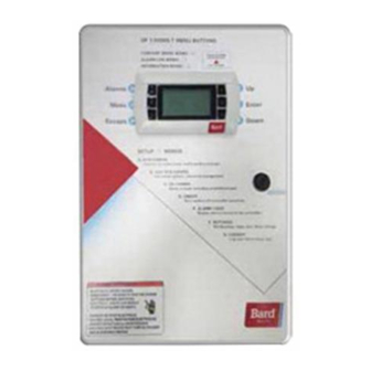
Page 36: Setting Up Lv1000 For Operation
FIGURE 36 LV1000 Controller Display and Interface (Status Screen Shown) UP KEY ALARM KEY ENTER KEY MENU KEY DOWN KEY ESCAPE KEY LV1000 interface key functions are the same as those shown for the TEC-EYE in Figure 32 on page 34. Setting Up LV1000 for Operation 12) Press UP or DOWN keys to change the value. -
Page 37: Configure Sensors
5. Configure Sensors 6) Press UP or DOWN key to change value to ON to enable sensor (or change value to OFF to The system will need to be configured for the disable sensor). number of temperature and humidity sensors installed. -
Page 38: Enter Total Number Of Units
4) Press UP or DOWN keys to scroll to Indoor To enable/disable Indoor Temperature 3: Temperature 1 (C6). 1) Press MENU key to go to the Main Menu 5) Press ENTER key to scroll to Enable (see screen. Figure 42). 2) Press UP or DOWN keys and ENTER key to 6) Press UP or DOWN key to change value to ON enter TECHNICIAN password 1313. -
Page 39: Verify Units Are Online
Additional programming information can be found In addition to being able to remotely view the units, in FUSION-TEC Service Instructions 2100-670 an alarm will be generated on the LV controller for and LV1000 Service Instructions 2100-673. units not communicating. -
Page 40: Additional Information
ADDITIONAL INFORMATION Menu Screens and Password Levels FIGURE 48 Adjusting Sensor Offset Value System Config: A1-A10 User Adv Sys Config: B1-B4 Technician I-O Config: C1-C18 Technician On/Off: User Alarm Logs: User Settings: Date/Time: Technician Language: User Network Config: Technician Serial Ports: Technician Reset to Factory Defaults Initialization To reset the LV controller to factory default settings:... -
Page 41: Unit Status Messages
TABLE 6 TABLE 7 Unit Status Messages LV1000 Status Messages Message Description Message Description Unit is on and in orphan mode with System is on and waiting for heat, Orphan Stby Ready no calls for heating or cooling cooling, etc. Freecooling System is actively economizing Unit is operating under power loss...