Table of Contents
Advertisement
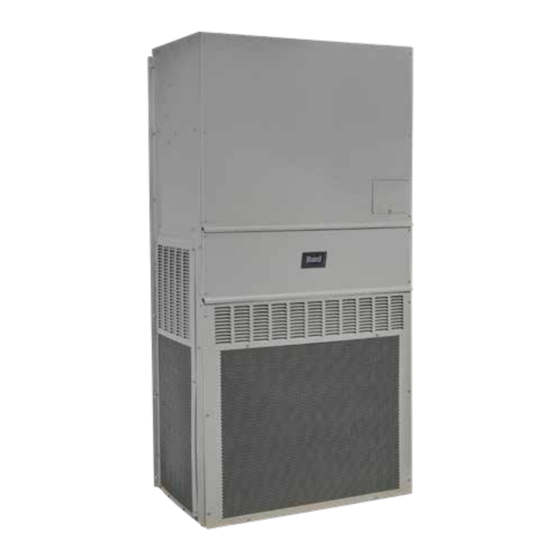
SERVICE INSTRUCTIONS
Wall-Mount Air Conditioner
NOTE: LC6000 controller is required for operation when multiple MULTI-TEC
wall-mount air conditioners are used.
MULTI-TEC
Bard Manufacturing Company, Inc.
Bryan, Ohio 43506
www.bardhvac.com
®
Models:
W42ACE*
W60ACE*
W42ACM*
W60ACM*
W42ACP*
W60ACP*
W48ACE*
W72ACE*
W48ACM*
W72ACM*
W48ACP*
W72ACP*
Manual:
Supersedes:
Date:
2100-725C
2100-725B
8-3-20
Page
1 of 39
Advertisement
Table of Contents
Troubleshooting

Related Manuals for Bard MULTI-TEC W42ACE Series


Summary of Contents for Bard MULTI-TEC W42ACE Series
- Page 1 W42ACP* W60ACP* W48ACE* W72ACE* W48ACM* W72ACM* W48ACP* W72ACP* NOTE: LC6000 controller is required for operation when multiple MULTI-TEC wall-mount air conditioners are used. Bard Manufacturing Company, Inc. Manual: 2100-725C Bryan, Ohio 43506 Supersedes: 2100-725B www.bardhvac.com Date: 8-3-20 Page 1 of 39...
-
Page 2: Table Of Contents
CONTENTS Enthalpy ........17 General Information ...........4 Air Conditioning System ........ 4 Economizer Modulation ......17 Wall-Mount Air Conditioner Units ....4 Emergency Cooling ........18 General ............4 Unit Disable ..........18 Compressor ..........18 Shipping Damage ......... 4 Additional Publications ......... -
Page 3: Figure 1 Multi-Tec Wall-Mount Unit Model Nomenclature
Figure 6 Last 24 Hour Tracking ...... 8 Figure 34 Removing Left Filter ...... 29 Figure 7 Last 24 Hour Tracking ...... 8 Figure 35 Removing Second Filter ....29 Figure 8 Software Version Information .... 8 Figure 36 Filter Tabs in Up Position ....29 Figure 9 Alarm Log Screen Breakdown.... -
Page 4: General Information
Air Conditioning System While these instructions are intended as a general recommended guide, they do not supersede any national The Bard air conditioning system is composed of and/or local codes in any way. Authorities having MULTI-TEC wall-mounted air conditioners matched... - Page 5 American Society of Heating, Refrigeration and Air WARNING Conditioning Engineers, Inc. (ASHRAE) 1791 Tullie Circle, N.E. Atlanta, GA 30329-2305 Telephone: (404) 636-8400 Fax: (404) 321-5478 Electrical shock hazard. National Fire Protection Association (NFPA) Have a properly trained individual perform Batterymarch Park these tasks.
-
Page 6: Using The Tec-Eye Tm
USING THE TEC-EYE FIGURE 2 TEC-EYE (Bard P/N 8301-059) Display and Interface (Status Screen Shown) UP KEY ALARM KEY MENU KEY ENTER KEY ESCAPE KEY DOWN KEY ALARM KEY UP KEY Allows viewing of active alarms Steps to next screen in the display menu... -
Page 7: Tec-Eye Screen Structure And Password Level
TABLE 1 displayed. See Table 2 for MULTI-TEC wall-mount unit LC6000/TEC-EYE Passwords (Defaults) status messages. TABLE 2 User 2000 Wall-Mount Unit Status Messages Technician 1313 Engineer 9254 Message Description Use UP or DOWN keys and ENTER key to enter password Unit disabled due to faulty Invalid Model # TEC-EYE Screen Structure and Password Level... -
Page 8: Quick Menu
FIGURE 6 The Quick Menu is displayed in the bottom right corner Last 24 Hour Tracking of the status screen (see Figure 2 on page 6). Alarm Log, Unit Information and Setpoints are available through the Quick Menu. Pressing the UP or DOWN keys while on the Status screen will change the Quick Menu icon displayed (see Figure 4). -
Page 9: Addressing Wall-Mount Units
NOTE: Each unit must have a unique address for the The letter Z represents a change to the software communication to work properly. Bard also that fixes existing features or user interface. recommends physically labeling each unit for ease in identification. -
Page 10: Executing A Self Test
Executing a Self Test 6. Reheat Valve Open 7. Cooling Off Execute a self test on each unit to verify the equipment 8. Electric Heat Stage 1 is functioning correctly. 9. Electric Heat Stage 2 1. Press MENU key to access the Main Menu screen. 10. -
Page 11: Alarms
ALARMS NOTE: Screenshots shown in this manual reflect Clearing Alarm Logs default settings (when applicable). To clear the alarm logs: Acknowledging/Clearing Alarms 1. Press MENU key to go to the Main Menu screen. Alarm conditions activate a red LED indicator that 2. -
Page 12: Refrigerant Low Pressure
mixed air alarm will need to be active for 120 seconds 3. Press UP or DOWN keys to scroll to Sys Config; before an alarm will be generated. press ENTER key. To adjust these values: 4. Press UP or DOWN keys to scroll to Alarm Config (A7);... -
Page 13: Freezestat
6. Press UP or DOWN keys to adjust value. 7. Press ENTER key to save. Freezestat When the coil temperature is below 30°F, the unit will generate a Freeze alarm on the TEC-EYE and a Freeze Temp alarm on the LC6000. This will operate the blower and turn off the compressor. -
Page 14: Control Operation
CONTROL OPERATION NOTE: Screenshots shown in this manual reflect Blower Speed 2: Nominal (N08) default settings (when applicable). This blower speed is available when the unit is in cooling, heating, orphan mode, freeze condition, free On/Off Control cool or continuous blower. The wall-mount unit can be turned on and off with the Blower Speed 3: High Sensible (N09) TEC-EYE. -
Page 15: Temperature Control
FIGURE 20 80°F (Setpoint + Stage 2 Diff On), the unit will enable Balanced Climate Enable/Disable mechanical cooling stage 1. If the control value is higher than 81°F (Setpoint + Stage 3 Diff On), the unit will enable mechanical cooling stage 2. Cooling Sequence –... -
Page 16: Heating Sequence
FIGURE 22 6. Press UP or DOWN keys to adjust value. Adjusting Cooling Differential Values 7. Press ENTER key to save. FIGURE 23 Adjusting Heating Differential Values Heating Sequence (see Figure 24) If the return air temperature is below 58°F (Setpoint + Stage 1 Diff On), the unit will enable electric heat Free Cooling stage 1. -
Page 17: Economizer Enable
to be selected therefore defaulting to a disabled state, 2. Outdoor relative humidity is below the OA Humid along with all sensors/alarms associated with it. Set outdoor humidity setpoint listed within the Sys. Config menu. (OA Humid Set humidity setpoint is Economizer Enable 80% RH by default.) The economizer will be enabled for cooling operation... -
Page 18: Emergency Cooling
6. Press UP or DOWN keys to adjust parameter value. 3. Press UP or DOWN keys to scroll to IO Config; press ENTER key. 7. Press ENTER key to save. 4. Press UP or DOWN keys to scroll to Digital In Economizer Note Config C1;... -
Page 19: Figure 29 Dehumidification Control
When the wall-mount unit receives a dehumidification call from the LC6000, the wall-mount unit will disable the economizer to force the system to use air conditioning and prevent any additional humidity from being introduced from outdoor air. The wall-mount unit will then turn on the air conditioning system which will remove moisture and cool the space. -
Page 20: Figure 30 Wall-Mount Unit Control Board
FIGURE 30 Wall-Mount Unit Control Board 24VAC GND + Communication Wire 24VAC Hot - Communication Wire Dirty Filter Switch High Pressure (CCM) 24VAC + Low Pressure Switch Y TO Compressor CCM Damper Blade Switch Digital Ground Mixed Air Temp Sensor Outdoor Air Temp Sensor 24VAC + Return Air Temp Sensor... - Page 21 TABLE 4 MULTI-TEC Wall-Mount Unit Control Board Terminals Terminal Function Type Form Rx+/Tx+ Communication Rx-/Tx- Communication Unit Disable Digital Dirty Filter Switch Digital High Pressure (CCM) Digital Low Pressure Switch Digital Not Used Damper Blade Switch Digital Not Used Digital Ground Mixed Air Temperature Sensor Analog Input 10K Ohm Curve J...
-
Page 22: General Refrigerant Information
AHRI capacity and Topping Off System Charge efficiency ratings were determined by testing with this If a leak has occurred in the system, Bard refrigerant charge quantity. Manufacturing recommends reclaiming, evacuating Table 5 on shows nominal pressures for the units. Since... - Page 23 TABLE 5 MULTI-TEC Cooling Pressures Air Temperature Entering Outdoor Coil °F Return Air Temp Model Pressure (DB/WB) Low Side 75/62 High Side Low Side W42AC 80/67 High Side Low Side 85/72 High Side Low Side 75/62 High Side Low Side W48AC 80/67 High Side...
-
Page 24: Componentry
COMPONENTRY Phase Monitor WARNING Used only on 3-phase equipment, the phase monitor is a compressor protection device that will prohibit operation of the compressor if the device senses a possible Electrical shock hazard. reverse-rotation situation due to incorrect phasing. On a call for compressor (and only compressor), the device Disconnect VAC power supply before servicing. -
Page 25: Short Cycle Protection/Delay-On-Break
time period is 2 minutes plus 10% of the delay-on- until power is cycled to the control or a loss of voltage break time period. To ensure that all of the units do not is present at Y terminal for more than ½ second. start at the same time, adjust the delay-on-break timer Test Mode on each unit to a slightly different delay time. -
Page 26: Pressure Service Ports
shipped with all the DIP switches in the 'off' or 'do not obtained at www.fastestinc.com/en/SCCA07H. See the ignore' position (see Figure 31). replacement parts manual for replacement core part numbers. If ignoring the brownout is needed because of the above conditions, three preset timers can be set by DIP Outdoor Fan Motor switches in order to delay signaling a power brownout Due to design considerations of the condenser section... - Page 27 TABLE 6 MULTI-TEC W42-72AC* Optional Accessories EHW4TA-A05 EHWA05-A10B EHWA05-A15B EHWA05-A20B EHW4TA-B06 EHWA05-B09B EHW6TA-B06 EHWA05-B15B EHW5TA-B18 EHW4TA-B18 EHW4TA-C09 EHW4TA-C15 EHW5TA-A05 EHW60A-B09B EHW70A-B09B EHW6TA-B18 EHW72A-A10B EHW72A-A15B EHW72A-A20B WMCB-05B WMCB-06B WMCB-08A WMCB-09A WMPD-01C WMCB-08B Manual 2100-725C Page 27 of 39...
-
Page 28: Maintenance And Troubleshooting
MAINTENANCE AND TROUBLESHOOTING Standard Maintenance Procedures 4. Manually spin fan and blower motors to ensure they turn freely. All motors are permanently lubricated, so no oil is necessary. WARNING 5. Inspect free cooling damper actuator and linkage. 6. Install new air filter; check for additional filter grilles internal to the structure. -
Page 29: Filters
Filters FIGURE 35 Removing Second Filter The filters can be serviced from the outside by removing the front control panel cover (see Figure 33). Two (2) 20" x 20" x 1" throwaway filters come standard with each unit. Additional 1" and 2" filter options are available as optional accessories. -
Page 30: Figure 38 Remove Four Screws
2. Locate the filter support brackets and remove the 6. Install the right 2" filter first followed by the left four (4) screws holding them to the top of the filter (see Figures 41 and 42). control panel (see Figure 38). NOTE: When installing new filters, make sure that airflow arrows on filters point up. -
Page 31: Dirty Filter Switch
Dirty Filter Switch dependent on filter type used, blower speed, unit ducting and other unit installation characteristics. 1. Disconnect all power to the unit. Remove control See Dirty Filter Switch Adjustment for instructions panel outer cover and upper front panel. on how to make proper switch adjustments. -
Page 32: Dirty Filter Switch Adjustment
3. With air filters installed and switch initially set at slightly clockwise. If the switch tripped after 75%, 0.4" W.C. (see Step 2 under Dirty Filter Switch turn the knob counter-clockwise (see Figure 44). on page 31), begin restricting the air filter of the 5. -
Page 33: Troubleshooting Nidec Selectech Ecm Motors
If the Motor Is Running higher than allowed, additional duct work is NOTE: Bard Models PA13242; PA13302; PA13362-A, -B; PA13422-A, -B, -C; PA13482-A, -B, -C; PA13602-A, -B, -C needed. 1. It is normal for the motor to rock back and forth contain the X13-Series Motors. -
Page 34: Figure 46 Motor Connections
TROUBLESHOOTING GE X13-SERIES ECM2.3 MOTORS ™ CONT’D. 2. Initiate a demand from the thermostat and check the Model X13 Communication Diagnostics 2. If the motor has proper high voltage and ground at A. If the low voltage communication is not voltage between the common and the appropriate motor The X13 motor is communicated through 24 VAC low voltage the L/L1, G and N/L2 connections, continue with... -
Page 35: 8301-057 Airflow Differential/Dirty Filter Switch
8301-057 Airflow Differential/Dirty Filter Switch FIGURE 47 8301-057 Air Differential Switch Terminals Terminals 1 − Normally Closed 2 − Normally Open 3 − Common NOTE: Contact position is in resting state. 8301-067 Outdoor Temperature/Humidity Sensor FIGURE 48 8301-067 Sensor Dip Switches 8301-067 sensor Temperature/Resistance and Humidity/Voltage tables on pages 34 and 35. -
Page 36: Resistance
TABLE 7 8301-067 Sensor: Temperature/Resistance Temperature Resistance Temperature Resistance Temperature Resistance Temperature Resistance Ω Ω Ω Ω -31.7 148,452.94 -10.6 48,892.46 10.6 18,337.51 31.7 7679.76 -31.1 143,910.37 -10.0 47,571.97 11.1 17,898.38 32.2 7515.86 -30.6 139,521.46 -9.4 46,291.29 11.7 17,471.09 32.8 7355.94 -30.0 135,280.55 -8.9... - Page 37 TABLE 8 8301-067 Sensor: Humidity/Voltage mA Output mA Output mA Output 4.000 mA 9.440 mA 14.880 mA 4.160 mA 9.600 mA 15.040 mA 4.320 mA 9.760 mA 15.200 mA 4.480 mA 9.920 mA 15.360 mA 4.640 mA 10.080 mA 15.520 mA 4.800 mA 10.240 mA 15.680 mA...
-
Page 38: 8408-044 Return Air Sensor/Suction Sensor
8408-044 Return Air Sensor/Suction Sensor TABLE 9 8408-044 Sensor: Temperature/Resistance Curve J Temperature Resistance Temperature Resistance Temperature Resistance Temperature Resistance ºF Ω ºF Ω ºF Ω ºF Ω -25.0 196871 13.0 56985 53.0 19374 89.0 7507 -24.0 190099 14.0 55284 52.0 18867 90.0... -
Page 39: Alarm Index
ALARM INDEX TABLE 10 Wall-Mount Unit Alarm Index Index Alarm Log Export Variable PGD Displayed Alarm Description Al_retain Error in the number of retain memory writings Al_Err_retain_write Error in retain memory writings Al_ReturnAir1In Circuit 1 Return Air Temperature Sensor Alarm Al_ReturnAir1High Circuit 1 High Return Air Temperature Alarm Al_MixedAir1In...