Table of Contents
Advertisement
Quick Links
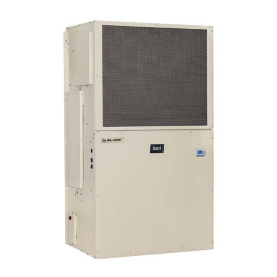
SERVICE INSTRUCTIONS
FUSION-TEC
NOTE: LC6000 controller is required for operation when
WR**BP* units are used.
Air Conditioner
WR35BPA WR36BPA WR58BPA
WR35BPB WR36BPB WR58BPB
Bard Manufacturing Company, Inc.
Bryan, Ohio 43506
www.bardhvac.com
Wall-Mount
®
Models:
Manual:
Supersedes:
Date:
2100-695C
2100-695B
7-2-21
Page
1 of 56
Advertisement
Table of Contents
Troubleshooting

Related Manuals for Bard FUSION-TEC WR35BPA


Summary of Contents for Bard FUSION-TEC WR35BPA
- Page 1 SERVICE INSTRUCTIONS FUSION-TEC Wall-Mount ® Air Conditioner Models: WR35BPA WR36BPA WR58BPA WR35BPB WR36BPB WR58BPB NOTE: LC6000 controller is required for operation when WR**BP* units are used. Bard Manufacturing Company, Inc. Manual: 2100-695C Bryan, Ohio 43506 Supersedes: 2100-695B www.bardhvac.com Date: 7-2-21 Page...
-
Page 2: Table Of Contents
CONTENTS Using the TEC-EYE ............6 Indoor Airflow ..............20 Indoor Airflow Components ........20 TEC-EYE Hand-Held Diagnostic Tool ........6 TEC-EYE Screen Structure and Password Level ....7 Blower .............20 Blower Status Switch .........22 TEC-EYE Acronyms ............7 Blower Status Alarm ........22 Main Status Screen ............7 Filters ..............22 Quick Menu ..............8 Dirty Filter Switch ..........22... - Page 3 Figure 36 Dirty Filter Switch and Filter Indicator Light ..24 Electric Heat Operation ..........37 Figure 37 Verifying Condenser Fan Output ......25 Bard Guard Anti-Theft System Option .......37 Figure 38 Fan Blade Setting .........25 Unit Disable Option Figure 39 Adjusting Liquid Pressure Transducer Values ..25 Inverter Option ...............38...
- Page 4 Air Conditioning System Conditioning and Ventilating Systems of Other Than Residence Type, NFPA No. 90A, and Residence Type This Bard air conditioning system is composed of Warm Air Heating and Air Conditioning Systems, NFPA FUSION-TEC WR Series wall-mounted air conditioners No.
- Page 5 ANSI Z535.5 Definitions: WARNING DANGER: Indicate[s] a hazardous situation which, if not avoided, will result in death or serious injury. The signal word “DANGER” is to be limited to the most Electrical shock hazard. extreme situations. DANGER [signs] should not be used for property damage hazards unless personal injury risk Have a properly trained individual perform appropriate to these levels is also involved.
-
Page 6: Using The Tec-Eye Tm
USING THE TEC-EYE FIGURE 1 TEC-EYE (Bard P/N 8301-059) Display and Interface (Status Screen Shown) UP KEY ALARM KEY MENU KEY ENTER KEY ESCAPE KEY DOWN KEY ALARM KEY UP KEY Allows viewing of active alarms Steps to next screen in the display menu... -
Page 7: Tec-Eye Screen Structure And Password Level
TEC-EYE Screen Structure and Password Level status are also displayed. See Table 2 for wall-mount unit status messages. Quick Menu Setpoints (Orphan Mode Temperature Control) TABLE 2 Information Unit Status Messages Alarm Log Main Menu Message Description System Config: A1-A10 User (2000) Adv Sys Config: B1-B8 Technician (1313) PLC is on and has not started running I-O Config: C1-C15 Technician (1313) -
Page 8: Quick Menu
The Quick Menu is accessible from the Main Status 4. Press UP or DOWN key on desired value until value Screen. Setpoints, Information and Alarm Log are displays correctly. available through the Quick Menu. Pressing the UP 5. Press ENTER key to save and scroll to next or DOWN keys while on the Main Status Screen will parameter. -
Page 9: A/C Circuit Measurements
Current software The Software Version screen displays the model versions and installation instructions are number of the unit as well as all software version available on the Bard website at http://www. information for the PLC (see Figure 9). This information bardhvac.com/software-download/... -
Page 10: Alarm Log
FIGURE 11 Alarm Log Executing Run Test The alarm log screens show a log of each alarm. There will be a log for when alarm occurred and if the alarm auto clears, it will show when the alarm cleared. Addressing Wall-Mount Units Each unit must have a unique address for the system to operate correctly with th LC controller (Ex: 1, 2, 3, ...14 depending on the number of units). -
Page 11: Run Test Parameter Descriptions
FIGURE 13 7. Press UP or DOWN key to change value to YES; Run Test: Motors & Sensors press ENTER key. 8. System will restart with default values. FIGURE 15 Restoring Factory Default Settings The A/C Circuit screen (Figure 14) displays all unit inputs, outputs and calculations associated with the A/C circuit operation. -
Page 12: Operation
OPERATION NOTE: Screenshots shown in this manual reflect the screen at the end of the alarm list (shown in Figure default settings (when applicable). 16) and press and hold the ALARM key for 3 seconds. Unit On/Off FIGURE 16 Clearing All Alarms The wall-mount unit can be turned on and off from the TEC-EYE. -
Page 13: Exporting 7 Day Logs
Once the first of the Bard that it is exposed to the entering airstream. An alarm... -
Page 14: Return Air Temperature Alarm
8. The update will not take effect until the cursor is 2. Press ENTER key to scroll to Cool Setpoint or Heat moved out of the Offset parameter. Setpoint (see Figure 4 on page 8). 9. Once adjusted, press the ESCAPE key several 3. -
Page 15: Cooling Sequence: Economizer Not Available
when the return air temperature reaches the setpoint To enable this delay: plus the stage off differential. 1. Press MENU key to go to the Main Menu screen. Staging 2. Press UP or DOWN keys and ENTER key to enter The unit will stage the cooling components based on TECHNICIAN password 1313. -
Page 16: Adjusting Heating Staging
7. Press ENTER key to save value and move cursor to 10. Repeat steps 6 through 9 for Stage 2 and Stage 3 Stage 1 Off Differential. differentials. 8. Press UP or DOWN keys to adjust number of 11. Press ESCAPE key several times to return to Main degrees below setpoint to turn cooling operation Menu screen. -
Page 17: Cycling Dehumidification Operation
units. The supervisory controller will then calculate the the compressor will be deactivated. After a 5-10 dehumidification demand based on how far above the second delay, the electric heat will energize and the setpoint and how long the RH level has been above the blower will go to rated speed for electric heat. -
Page 18: System Pressures
The valve can also be opened or closed using the EEV Suction Pressure Transducer service tool (Bard Part # 2151-021). This magnetic EEV The unit has a pressure transducer installed on the service tool (shown in Figure 26) is used to manually suction line between the evaporator coil and compressor. -
Page 19: Troubleshooting The Suction Pressure Transducer
FIGURE 29 Troubleshooting the Suction Pressure Transducer Adjusting Suction Temperature Sensor Values 0-250 psig -5v Nominal .5 – 4.5v Actual 4v/250 psig = .016 volts per 1 psig Example: 125 psig x .016 + .5 volts = 2.5 volts Formula for Tech: Measured Pressure x .016 + Sensor Offset = Expected Transducer Signal Voltage (see Figure 28). -
Page 20: Eev Operation
Indoor Airflow 8. Press UP or DOWN keys to change to the desired Alarm Delay value. Indoor Airflow Components 9. Press ENTER key to save the value. Blower The unit is equipped with a blower that is driven by FIGURE 30 an electronically commutated motor (ECM). - Page 21 TABLE 5A TABLE 5C WR35BP* Blower Speeds WR58BP* Blower Speeds Speed Controller Speed Controller Mode Mode Percentage Output Volts Percentage Output Volts High Sensible Full High Sensible 75.0 7.5 v 2180 80.0 8.0 v 1400 Load Cooling Full Load Cooling High Sensible Part High Sensible 50.0...
-
Page 22: Blower Status Switch
Blower Status Switch Blower Status Alarm The unit is equipped with a differential pressure airflow If the blower is commanded on and the fan status switch to monitor the blower (see Figure 32). If the switch (differential pressure) has not indicated the fan blower is turned on and the switch doesn't close to is running within 45 seconds, the system will generate indicate there is differential pressure between the inlet... -
Page 23: Dirty Filter Alarm
All units tested equipped with MERV 8 filters. Appropriate supply (SG) and return (RG) grilles installed during testing. Pressure switch adjustment may be necessary due to variations in filter type, installation and room pressure. Bard recommends filter switch be set at 50% filter blockage or less. Higher settings may significantly hinder unit performance. Manual 2100-695C... -
Page 24: Blower Speed Control
FIGURE 36 Dirty Filter Switch and Filter Indicator Light ADJUSTMENT INDICATOR ARROW FILTER LIGHT ADJUSTMENT KNOB SCREW TO REMOVE COVER COVER TUBE LOCATED IN AIRSTREAM AFTER FILTER TUBE LOCATED IN MIS-3901 AIRSTREAM BEFORE FILTER 6. Press UP or DOWN keys to change ON or OFF Condenser Fan MIS-3901 value. -
Page 25: Liquid Line Pressure Transducer
FIGURE 37 Liquid Line Pressure Transducer Verifying Condenser Fan Output The unit has a pressure transducer installed on the liquid line between the condenser and electronic expansion valve (EEV). The transducer is used for system monitoring of the liquid side system pressures. This information is used to indicate when outdoor coil cleaning is necessary based on outdoor conditions and system pressures. -
Page 26: Liquid Pressure Transducer Alarm
FIGURE 40 FIGURE 41 Voltage to Pressure: Adjusting Liquid Temperature Values Liquid Pressure Transducer Condenser Fan Operation Condenser Fan Speed Control Liquid Pressure Transducer Alarm The unit is equipped with a variable speed ECM (electronically commutated motor) condenser fan which When the liquid line pressure sensor value is out allows the unit to better control head pressures for of range (0-650 PSIG), the controller will generate... -
Page 27: Compressor
FIGURE 42 Liquid Pressure Control Setpoint conditions. The process for this system is as follows: If reverse operation for over 1 hour may have a negative the liquid pressure falls below 275 PSI, the condenser impact on the bearing due to oil pump out. fan will turn off. -
Page 28: Short Cycle Protection/Delay-On-Break
time, adjust the delay-on-break timer on each unit to a Test Mode slightly different delay time. By rapidly rotating the potentiometer (POT) clockwise Short Cycle Protection/Delay-on-Break (see Figure 43), all timing functions will be removed for testing. An anti-short cycle timer is included to prevent short cycling the compressor. -
Page 29: High Pressure Safety Switch
If ignoring the brownout is needed because of the pressure switch, which is 650 PSI), the system will above conditions, three preset timers can be set by DIP disable stage 2 of mechanical cooling. switches in order to delay signaling a power brownout Phase Monitor for a specific length of time after compressor contactor Used only on three phase equipment, the phase monitor... -
Page 30: Compressor Low Temperature Limit
Additional Compressor Alarms 6. Press UP or DOWN keys to change the value. 7. Press ENTER key to save value and move the Refrigerant Low Pressure Alarm cursor to next parameter or top of screen. When the suction pressure transducer indicates a 8. -
Page 31: Dust Sensor
To verify the output from the controller to the actuator: The dust sensor can be verified by: 1. Press MENU key to go to the Main Menu screen. 1. Press MENU key to go to the Main Menu screen. 2. Press UP or DOWN keys and ENTER key to enter 2. -
Page 32: Damper Blade
3. Press UP or DOWN keys to scroll to System Config; Disabling the dust sensor in I/O Config disables this alarm. press ENTER key. To adjust the dust sensor alarm setpoint: 4. Press UP or DOWN keys to scroll to Economizer Setup A3. -
Page 33: Damper Failed To Open Alarm
FIGURE 51 Damper Failed to Close Alarm Damper Switch When the controller commands the economizer damper actuator to the 0% position and the damper switch indicates the damper is not closed, after a delay of 300 seconds the controller will generate a damper failed to close alarm. -
Page 34: Outdoor Temperature Sensor Failure Alarm
FIGURE 53 Outdoor Humidity Sensor Failure Alarm Outdoor Air Sensor When the sensor reads a value that is outside of the acceptable 0 to 100% RH range, an alarm will be generated indicating the sensor has failed. This alarm condition will disable the economizer when the mode is set to temperature and humidity or enthalpy. -
Page 35: High Supply Air Temperature Alarm
High Supply Air Temperature Alarm 7. Press ENTER key to save value and scroll to Delay. When the supply air temperature is above 80°F for 8. Press UP or DOWN keys to adjust the delay value. 120 seconds, an alarm will be generated and the NOTE: This delay is also applied to the high supply air economizer will be disabled until the cooling call has temperature alarm. -
Page 36: Figure 58 Economizer Setup A3
FIGURE 58 9. Press UP or DOWN keys to change the parameter to the desired value. Economizer Setup A3 10. Press ENTER key to save the value and scroll to the next parameter. 11. Press UP or DOWN keys to change the (outdoor temperature) Off Diff parameter to the desired value. -
Page 37: Emergency Cooling Mode
The model and serial number are entered These devices are used with the Bard Guard BG1000 anti- at the factory, and should be retained during a software theft controller to provide an anti-theft measure. -
Page 38: Inverter Option
Unit Disable Option The unit is equipped with an input that can be used with a smoke detector or unit disable switch with a dry contact. When this input indicates a smoke event, the system will be shut down. The alarm will automatically clear when the alarm condition is no longer present. -
Page 39: Figure 59 Fusion-Tec Wr Series Unit Control Board
FIGURE 59 FUSION-TEC WR Series Wall-Mount Unit Control Board 8301-068-004* + Communication Wire – Communication Wire 5VDC Micro USB FieldBus2 24VAC Hot 24VAC Common Unit Disable Relay/Switch Jumper Dirty Filter Switch 24VAC + Compressor Alarm Relay Power Loss Relay (if equipped) Control To CCM Y Stand-by... - Page 40 TABLE 11 FUSION-TEC WR Series Wall-Mount Unit Control Board Terminals Terminal Function Type Form Rx+/Tx+ Communication Rx-/Tx- Communication Unit Disable Relay/Switch Digital Input Dirty Filter Switch Digital Input Compressor Alarm Relay Digital Input Power Loss Relay (if used) Digital Input Not Used Damper Blade Switch Digital Input...
-
Page 41: Figure 60 Fusion-Tec Wr Series Nomenclature
5 – Internal and External Cabinet Component Coating, Coated Evaporator Coil, Coated Condenser Coil ACCESSORIES AND CONTROLS OPTIONS X – Standard accessories including airflow sensor, dirty filter sensor, pressure transducers, crankcase heater S – All standard accessories plus additional Bard Guard security features and security frame Manual 2100-695C... -
Page 42: Refrigerant Information
Topping Off System Charge AHRI capacity and efficiency ratings were determined by testing with this refrigerant charge quantity. If a leak has occurred in the system, Bard Manufacturing recommends reclaiming, evacuating Table 12 shows nominal pressures for the units. Since... - Page 43 This unit employs high-flow Coremax valves instead of To change a Coremax valve without first removing the the typical Schrader type valves. refrigerant, a special tool is required which can be obtained at www.fastestinc.com/en/SCCA07H. See the WARNING! Do NOT use a Schrader valve core removal replacement parts manual for replacement core part tool with these valves.
-
Page 44: Maintenance
LED will illuminate. As long as for the evaporator or condenser coil. the blue LED is illuminated, the Bard Guard system • Condenser coil: Remove the upper side panels is disarmed and will remain disarmed depending from the condenser section. -
Page 45: Troubleshooting
TROUBLESHOOTING 8301-067 Outdoor Temperature/Humidity Sensor 8301-067 Sensor Connections This unit utilizes a two wire 4-10mA signal from Tables 13 and 14 on pages 46 and 47 are correlation the 8301-067 sensor to communicate outdoor charts for troubleshooting the sensor with a test meter: humidity and a 10KΩ... - Page 46 TABLE 13 8301-067 Sensor: Temperature to Thermocouple Resistance Temperature Resistance Temperature Resistance Temperature Resistance Temperature Resistance Ω Ω Ω Ω -31.7 148,453 -10.6 48,892 10.6 18,338 31.7 7680 -31.1 143,910 -10.0 47,572 11.1 17,898 32.2 7516 -30.6 139,521 -9.4 46,291 11.7 17,471 32.8...
- Page 47 TABLE 14 8301-067 Sensor: Relative Humidity to Humidity Sensor Current Output Humidity Signal Humidity Signal Humidity Signal % RH % RH % RH 4.000 9.440 14.880 4.160 9.600 15.040 4.320 9.760 15.200 4.480 9.920 15.360 4.640 10.080 15.520 4.800 10.240 15.680 4.960 10.400...
-
Page 48: 8301-067 Humidity Sensor Test Value Outputs
8301-067 Humidity Sensor Test Value Outputs 8301-067 Humidity Sensor Calibration This sensor has the ability to output fixed test signals The 8301-067 sensor has the ability to be calibrated when testing/troubleshooting sensor operation. via the sensor control board through the use of the These settings are to be used for sensor testing/ DIP switches and/or the use of ZERO P1 or SPAN P2. -
Page 49: 8301-057 Blower Status Switch/Dirty Filter Switch
8301-057 Blower Status Switch/Dirty Filter Switch FIGURE 64 8301-057 Air Differential Switch Terminals Terminals 1 − Normally Closed 2 − Normally Open 3 − Common NOTE: Contact position is in resting state. P1: Hose Connected P2: Stub Connected Manual 2100-695C Page 49 of 56... -
Page 50: 8301-073 Dust (Particulate) Sensor
8301-073 Dust (Particulate) Sensor TABLE 15 8301-073 Sensor: Dust/Volts Dust Signal Dust Signal Dust Signal 0.00 1.70 3.40 0.05 1.75 3.45 0.10 1.80 3.50 0.15 1.84 3.54 0.19 1.89 3.59 0.24 1.94 3.64 0.29 1.99 3.69 0.34 2.04 3.74 0.39 2.09 3.79 0.44... -
Page 51: 8612-061 Dust (Particulate) Sensor Control Board
8612-061 Dust (Particulate) Sensor Control Board 8612-061 Control Board Output Signal Not Responsive 3. With a voltmeter, measure voltage between the to Dust following terminals: 1. With a voltmeter, verify 24VAC present across A. Component U1 pin 2 and terminal block pin 4 24VAC pin terminals. -
Page 52: Figure 66 Dust Sensor Alarm Board Power Supply Check
FIGURE 66 Dust Sensor Alarm Board Power Supply Check Manual 2100-695C Page 52 of 56... -
Page 53: 8408-044 Return Air Sensor/Suction Sensor
8408-044 Return Air Sensor/Suction Sensor TABLE 16 8408-044 Sensor: Temperature/Resistance Curve J Temperature Resistance Temperature Resistance Temperature Resistance Temperature Resistance ºF ºC Ω ºF ºC Ω ºF ºC Ω ºF ºC Ω -31.7 196,871 -10.6 56,985 10.6 19,374 31.7 7507 -31.1 190,099 -10.0... -
Page 54: 8301-066 Supply Air Sensor
8301-066 Supply Air Sensor TABLE 17 8301-066 Sensor: Temperature/Resistance Temperature Resistance Temperature Resistance Temperature Resistance °F °C Ω °F °C Ω °F °C Ω 29,490 96.8 6501 161.6 1868 33.8 28,157 98.6 6260 163.4 1810 35.6 26,891 100.4 6028 165.2 1754 37.4 25,689... -
Page 55: 8406-157 Liquid Line Pressure Transducer
8406-157 Liquid Line Pressure Transducer TABLE 18 8406-157 0-650psi Pressure Transducer: Pressure/DC Voltage Pressure Signal Pressure Signal Pressure Signal Pressure Signal 0.500 11.2 1.515 22.5 2.531 33.7 3.546 0.531 11.6 1.546 22.8 2.562 34.0 3.577 0.562 11.9 1.577 23.1 2.592 34.4 3.608 0.592... -
Page 56: 8406-158 Suction Pressure Transducer
8406-158 Suction Pressure Transducer TABLE 19 8406-158 0-250psi Pressure Transducer: Pressure/DC Voltage Pressure Signal Pressure Signal Pressure Signal Pressure Signal 0.500 1.524 2.548 13.1 3.572 0.532 1.556 2.580 13.2 3.604 0.564 1.588 2.612 13.3 3.636 0.596 1.620 2.644 13.5 3.668 0.628 1.652 2.676...