Endress+Hauser Prosonic S FMU90 Operating Instructions Manual
Level measurement, alternating pump control, rake control
Hide thumbs
Also See for Prosonic S FMU90:
- Description (217 pages) ,
- Operating instructions manual (182 pages) ,
- Brief operating instructions (56 pages)

Related Manuals for Endress+Hauser Prosonic S FMU90


Summary of Contents for Endress+Hauser Prosonic S FMU90
-
Page 1: Operating Instructions
Operating Instructions Prosonic S FMU90 Level Measurement Alternating Pump Control Rake Control BA288F/00/en/10.07 Valid as of software version 02.00.00... -
Page 3: Table Of Contents
"back to home" ......75 Parts of the Prosonic S FMU90 ....7 The "Relay/Controls"... - Page 4 Table of Contents Technical Data....160 13.1 Technical data at a glance ....160 Operating menu .
-
Page 5: Safety Instructions
Safety Instructions Designated use The Prosonic S FMU90 is a transmitter for the ultrasonic sensors FDU91, FDU91F, FDU92, FDU93, FDU95 and FDU96. The sensors of the former class FDU8x can be connected as well. The transmitter version for level measurements (product structure according to section 2.3: FMU90 - *1**********) can be applied for different measuring tasks, e.g.:... -
Page 6: Notes On Safety Conventions And Symbols
Safety Instructions Notes on safety conventions and symbols In order to highlight safety-relevant or alternative operating procedures in the manual, the following conventions have been used, each indicated by a corresponding symbol in the margin. Safety conventions Warning! A warning highlights actions or procedures which, if not performed correctly, will lead to personal injury, a safety hazard or destruction of the instrument "... -
Page 7: Identification
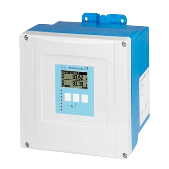
Identification Identification Parts of the Prosonic S FMU90 2.1.1 FMU90 in the field housing 9 Ma 0- J1 ni c P ro M A4 r Co / NE r.- No … 4 … °C x° C > 60 II 3... -
Page 8: Nameplate (Example)
Identification 2.1.3 FMU90 with remote display and operating module for cabinet door and switchboard mounting (96x96 mm) u rg u lb 0 -J D -7 o .: O rd r. -N … 4 … 0 °C x °C > 6 II 3 ifi ca la b... -
Page 9: Product Structure
Identification Product structure Approval Non-hazarous area ATEX II 3D CSA General Purpose Application Level + pump control, alternating Flow + totalizer + level + sample control + preprogrammed OCM flow curves Level + additional pump control Universal instrument (Level + Flow + Additional pump control) Housing, material Field mounting PC, IP66 NEMA 4x DIN rail mounting PBT, IP20... -
Page 10: Supplied Documentation
Identification Supplied documentation 2.5.1 Operating instructions (for transmitter FMU90) Depending on the instrument version, the following operating instructions are supplied with the Prosonic S FMU90: Operating instructions Output Application Instrument version • level measurement FMU90 - *******1**** BA 288F • alternating pump control FMU90 - *******2**** •... -
Page 11: Certificates And Approvals
The device complies with the applicable standards and regulations as listed in the EC declaration of conformity and thus complies with the statutory requirements of the EG directives. Endress+Hauser confirms the successful testing of the device by affixing to it the CE mark. -
Page 12: Installation
Installation Installation Incoming acceptance, transport, storage 3.1.1 Incoming acceptance Check the packing and contents for any signs of damage. Check the shipment, make sure nothing is missing and that the scope of supply matches your order. 3.1.2 Transport, storage Pack the measuring instrument so that it is protected against impacts for storage and transport. The original packing material provides the optimum protection for this. - Page 13 Installation 3.2.2 Installation conditions Weather protection In order to avoid excessive sunlight exposure, the instrument should be mounted in a position which is protected against direct sunlight or a protection cover should be applied (s. chapter "Accessories"). Overvoltage protection In order to protect the Prosonic against overvoltages (especially if mounted outdoors), connection of an overvoltage protection is recommended (s.
-
Page 14: Mounting The Din-Rail Housing
Installation Mounting the DIN-rail housing 3.3.1 Dimensions of the DIN-rail housing The dimensions of the DIN-rail housing depend on the instrument version. The version determines, which terminal areas the Prosonic S contains. The dimensions are influenced by the following features of the product structure (see chapter 2.3): •... - Page 15 Installation Sum = 4 (4 optional terminal areas) ≈ 0,9 kg EN 60715 TH 35x7,5/15 L00-FMU90xxx-06-00-00-xx-009 Dimensions in mm Example 10 20 30 40 50 60 70 80 90 100 110 120 FMU90 - feature and option of corresponds to the following present? the product structure terminal area...
- Page 16 Installation 3.3.2 Installation conditions • The DIN-rail housing must be mounted outside hazardous areas in a cabinet. • The housing is mounted on a DIN rail EN 60715 TH 35x7,5 or TH 37x15. • Do not install the instrument in the vicinity of high-voltage lines, motor lines, contactors or frequency converters.
-
Page 17: Mounting The Remote Display And Operating Module
Installation Mounting the remote display and operating module 3.4.1 Scope of delivery If the Prosonic S is ordered with the display for cabinet door mounting, the following is contained in the scope of delivery: • Display and operating module, 96x96 mm •... -
Page 18: Mounting Of The Sensors
Installation 3.4.4 Adaption plate If an opening of 138 mm x 138 mm and the remote display of the Prosonic FMU860/861/862 are already present, you can use the adaption plate (Order Code: 52027441, s. chapter "Accessories"). It is inserted into the remote display of the FMU860/861/862. Note! The adapter plate is mounted directly in the housing of the old remote display of the FMU86x series. -
Page 19: Wiring
Wiring Wiring Warning! The instrument may only be installed if the supply voltage is switched off. Terminal compartment 4.1.1 Terminal compartment of the field housing The field housing has a separate terminal compartment. It can be opened after loosening the four screws of the lid. - Page 20 Wiring 4.1.3 Terminal compartment of the DIN-rail housing Single instrument l00-fmu90xxx-04-00-00-xx-003 The catch can be unlocked by slightly pressing onto the clip. Then, the cover of the terminal compartment can be opened. Several instruments mounted side by side L00-FMU90xxx-04-00-00-xx-012 Open the catch of the cover (e.g. by a screwdriver). Pull the cover out by approx.
-
Page 21: Terminal Assignment
Wiring Terminal assignment Pluggable spring-force terminals for connection of the cables are supplied in the terminal compartment. Rigid conductors or flexible conductors with cable sleeve can directly be inserted and are contacted automatically. Conductor cross section 0,2 mm - 2,5 mm Cable and sleeve cross section 0,25 mm - 2,5 mm... - Page 22 4 0: < 8 V or 81 and 82 interconnected 1: > 16 V or 81 and 82 not interconnected temperature input 83, 84, 85 temperature input: see section "Connection of a temperature sensor" • PT100 • FMT131 (Endress+Hauser)
- Page 23 Wiring In this case, terminals 9/10/11 are not present on terminal area A. Warning! When using the public supply mains, an easily accesible power switch must be installed in the proximity of the device. The power switch must be marked as a disconnector for the device (IEC/ EN 61010) Note! •...
-
Page 24: Sensor Connection
Wiring Sensor connection 4.3.1 Connection diagram FDU91/92 FDU91 (FDU80/80F/81/81F/82) (FDU80/81) max. 30 m max. BN BU FDU91/92 300 m (FDU80/80F/81/81F/82) 24 VDC (12) (13) (12) (13) (14) (14) FMU90 FMU90 FDU91F/93/95/96 FDU91F/93/95/96 (FDU83/84/85/86) (FDU83/84/85/86) max. 30 m RD GNYE RD GNYE FDU91F/93/95/96 max. - Page 25 If the terminal box is installed in explosion hazardous areas, all applicable national guidelines must be observed. Suitable extension cables can be obtained from Endress+Hauser (s. chapter "Accessories") Alternatively, cables with the following properties can be used: • Number of cores according to the connection diagram (see above) •...
-
Page 26: Connection Of The Sensor Heater (For Fdu91)
Wiring Connection of the sensor heater (for FDU91) The FDU91 sensor is available in a version with heater. The power for this heater must be provided by an external power supply unit. The supply voltage is connected to the brown (BN) and blue (BU) strands of the sensor cable. - Page 27 Wiring 4.4.2 Connection in the DIN-rail housing The supply voltage must be provided in the cabinet, e.g. by a terminal on the DIN-rail: FMU90 Sync Service Fuse Display HART 0/4…20mA FDU- Sensor Relay FDU91 24 VDC L00-FMU90xxx-04-00-00-xx-014 Note! The terminal module supplied with the sensor can also be used for connection of the supply voltage. For the terminal assignment on this module see page 26.
-
Page 28: Connection Of External Switches (For Fmu90-********B***)
Wiring Connection of external switches (for FMU90-********B***) FMU90 FMU90 24 V 24 V A: 71, 74, 77, 80 B: 72, 75, 78, 81 C: 73, 76, 79, 82 L00-FMU90xxx-04-00-00-xx-021 The maximum short-circuit current at 24 V is 20 mA. -
Page 29: Connection Of A Temperature Sensor
N" in the "temp. measurement" parameter. Note! If the option "alarm" has been selected for the case of an error in external temperature sensor, this alarm is indicated by the alarm relay. 4.6.1 FMT131 (Endress+Hauser) (connectable to FMU90-********B***) FMU90 FMU90 FMU90... - Page 30 Wiring 4.6.2 Pt100 (connectable to FMU90-********B***) FMU90 FMU90 Pt100 Pt100 L00-FMU90xxx-04-00-00-xx-020 A: Pt100 with 3-wire connection; B: Pt100 with 4-wire connection (one connector remains unused) Note! A Pt100 with 2-wire connection may not be used due to its insufficient measuring accuracy. Warning! A Pt100 may not be connected in explosion hazardous areas.
-
Page 31: Shortening The Sensor Cable
Wiring Shortening the sensor cable If required, the sensor cable can be shortened. Please note: • Do not damage the cores when removing the insulation. • The cable is shielded by a metallic braiding. This shielding serves as a return cable and corresponds to the black (BK) strand of the unshortened cable. -
Page 32: Synchronization Line
Wiring Synchronization line • If wiring several Prosonic S (FMU90/FMU95) which are mounted in a common cabinet and FMU90 FMU90 FMU90 if the sensor cables run in parallel, the synchronization terminals (39 and 40) must be interconnected. • Up to 20 instruments can be synchronized in …... -
Page 33: Potential Equalization
Wiring 4.10 Potential equalization 4.10.1 Potential equalization in the field housing Warning! The grounding line of the sensors FDU91F/93/ 95/96 and FDU83/84/85/86 must be connected to the local potential equalization system after a maximum of 30 m (see section 4.3.1). The metallic terminal block (A) in the field housing can be used for this. -
Page 34: Post-Connection Check
Wiring 4.10.2 Potential equalization for the DIN-rail hosuing If the DIN-rail housing is used, the potential equalization must be connected in the cabinet, e.g. at a metallic DIN rail: Warning! The grounding line of the sensors FDU91F/93/95/96 and FDU83/84/85/86 must be connected to the local potential equalization system after a maximum of 30 m (see section 4.3.1). -
Page 35: Operation
Operation Operation Operating options • via the operating and display module at the Prosonic S (if present) • via the service interface of the Prosonic S with the Commubox FXA291 and the operating program "ToF Tool - FieldTool Package" or "FieldCare" •... -
Page 36: Display Symbols
Operation Display symbols Symbol Meaning Operating mode of the instrument User User parameters can be edited. Service parameters are locked. Diagnosis The service interface is connected. Service User and service parameters can be edited. Locked All parameters are locked. Locking state of the currently displayed parameter Display parameter The parameter can not be edited in the current operating mode of the instrument. - Page 37 Operation Keys (softkey operation) The function of the keys depends on the current position within the operating menu (softkey functionality). The key functions are indicated by softkey symbols in the bottom line of the display. Symbol Meaning Move downwards Moves the marking bar downwards within a selection list. Move upwards Moves the marking bar upwards within a selection list.
-
Page 38: The Operating Menu
Operation Key combination Meaning Locking Locks the instrument against parameter changes. The instrument can only be unlocked again by the keys. 5.2.2 The operating menu Structure of the menu The parameters of the Prosonic S are organized in an operating menu (consisting of a main menu and several submenus). - Page 39 Operation Parameter types Display parameters Parameters for which the symbol is dis- played in the left bottom corner of the display module, are either locked or display-only para- meters. L00-FMU90xxx-07-00-00-en-041 Editable parameters Parameters, for which the symbol is dis- played in the left bottom corner of the display module, can be entered for editing by pressing The editing procedure depends on the type of parameter:...
- Page 40 Operation Navigation within the menu (Example) L00-FMU90xxx-19-00-00-en-050...
- Page 41 Operation Entering the menu The navigation always starts from the main screen (measured value display ). From there, the following menus can be opened by the keys: FMU90 shortcut menu main menu daily counter* level flow tag marking envelope curve language device information password/reset...
- Page 42 Operation Selecting a submenu In the main menu, press W or V until the main menu required submenu is marked by the bar. Note! The symbols indicate that the selection list contains more items than can be displayed on the module. Press W or V several times, to mark one of the hidden items.
- Page 43 Operation Selecting a parameter By pressing U or T you can switch between the parameter sets of the current submenu. For each parameter set the values of all its parameters are displayed. In order to change one of the values, proceed as follows: Press U or T, until you have reached the required parameter set.
- Page 44 Operation Editing a parameter with selection list Press W or V, until the required option is marked by the bar (in the example: "turb. surface"). Note! The symbols indicate that the selection list contains more items than can be displayed on the module. Press W or V several times, to mark one of the hidden items.
- Page 45 Operation Entering numbers and characters When you select a numeric parameter ("empty calibration", "full calibration" etc.) or an alpha- numeric parameter ("device marking" etc.), the editor for numbers and text strings appears. Enter the desired value in the following way: The cursor is at the first digit.
- Page 46 Operation Special editing functions Within the editor for alphanumeric characters, pressing S or O does not only lead to numbers and characters but also to the following symbols for special editing functions. They simplify the editing procedure. L00-FMU90xxx-19-00-00-yy-043 Enter: The number left of the cursor is transferred to the instrument. L00-FMU90xxx-19-00-00-yy-044 Escape: The editor is closed.
- Page 47 Operation L00-FMU90xxx-19-00-00-yy-047 Delete: The current digit and all digits to its right are deleted. Return to the measured value display By pressing the left and middle keys FMU90 simultaneously you can return • from a parameter to the parameter set •...
-
Page 48: Operation Via Endress+Hauser Operating Tool ("Tof Tool - Fieldtool Package" Or "Fieldcare")
Operation Operation via Endress+Hauser operating tool ("ToF Tool - Fieldtool Package" or "FieldCare") L00-FMU90xxx-19-00-00-en-087 Operation via the ToF Tool - Fieldtool Package is similar to the operation via the display module. • The operating menu can be found in the navigation bar (a). -
Page 49: Lock/Unlock Configuration
Operation Lock/unlock configuration 5.5.1 Software locking Locking Go to the parameter "device properties/passoword-reset/code" and enter a value ≠100. The instrument is locked against parameter changes. symbol appears on the display. Unlocking If you try to change a parameter, the "password-reset" parameter set appears. Select the "code" parameter and enter "100". -
Page 50: Reset To The Default Configuration
Operation 5.5.4 Indication of the locking state The current locking state of the instrument is displayed in the parameter "device properties/ password-reset/status". The following states may occur: • unlocked All parameters (except of service parameters) can be changed. • code locked The instrument has been locked via the operating menu. -
Page 51: Commissioning
Commissioning Commissioning Warning! For the version with field housing: The instrument may only be operated if the field housing is closed. Structure and Functions of the Prosonic S 6.1.1 Function blocks The Prosonic S contains various function blocks. During the commissioning procedure the blocks are linked to each other in order to perform the desired measuring task. - Page 52 Commissioning 2-channel level measurement Display Current output 1 Sensor 1 Level 1 +HART FDU9x Sensor 2 Level 2 Current output 2 Alarm Relay 1 FDU9x L00-FMU90xxx-19-00-00-en-080 Pump control Display Sensor 1 Level 1 Current output 1 Pump control Relay 2 FDU90 Relay 3 Relay 4...
-
Page 53: First Setup
Commissioning First setup Note! This chapter describes the commissioning of the Prosonic S via the display and operating module. Commissioning via ToF Tool, FieldCare or the HART handheld terminal DXR375 is similar. For further instructions refer to the ToF Tool Operating Instructions, the FieldCare Online Help or the Operating Instructions supplied with the DXR375. -
Page 54: Preparing The Basic Setup
Commissioning Preparing the basic setup After the first setup the main screen appears. However, the displayed value does not correspond to the real level before you have performed the basic setup. To do so, enter the main menu by pressing "Menu" (right key). Note! In the "calibr. -
Page 55: Basic Setup
Commissioning Basic setup 6.4.1 Overview The following table gives an overview of the basic setup for level measurements. Detailed information on the parameters can be found in the sections 6.4.2. to 6.4.11. Step Parameter Set Parameter Remarks s. section Configuring the sensor LVL N sensor selection input Allocate a sensor to the channel. - Page 56 Commissioning Step Parameter Set Parameter Remarks s. section Interference echo suppression distance correction act. distance 1 Indicates the currently measured distance between the sensor membrane 6.4.8 act. distance 2 and the product surface. 6.4.9 Check distance Compare the indicated distance with the real value: •...
- Page 57 Commissioning 6.4.2 "LVL N sensor selection" (N = 1 or 2) LVL1 sensor sel. L1003 ⇒ input: sensor selection: detected: "input" Use this parameter to assign a sensor to the channel. Selection: • no sensor • sensor 1 • sensor 2 (only for 2-channel instruments) "sensor selection"...
- Page 58 Commissioning 6.4.3 "LVL N application parameters" (N = 1 or 2) LVL1 appl. para. L1004 ⇒ tank shape: medium property: process cond.: "tank shape" Use this parameter to specify the tank shape of your application. Selection: dome ceiling horizontal cyl bypass stilling well (ultrasonic guide pipe)
- Page 59 Commissioning "process conditions" Use this parameter to specify the process conditions of your application. The filters of the signal evaluation are automatically adjusted to the selected conditions. "process conditions" for the following situations Example filter settings standard liquid for all fluid applications which do The filters and output damping are set not fit in any of the following to average values.
- Page 60 Commissioning 6.4.4 "LVL N empty calibration" (N = 1 or 2) LVL1 empty cal. L1005 ⇒ empty E: 0,00 m "empty E" Use this parameter to specify the empty distance E, i.e. the distance between the sensor membrane and the minimum level (zero point).
- Page 61 Commissioning 6.4.5 "LVL N full calibration" (N = 1 or 2) LVL1 full calib. L1006 ⇒ full F: 0,00 m block.dist. BD: "full F" Use this parameter to specify the span F, i.e. the distance from the minimum level to the maximum level. 20 mA 100% –...
- Page 62 Commissioning 6.4.6 "LVL N unit" (N = 1 or 2) LVL 1 unit L1007 ⇒ unit level: level 1: distance: "unit level" Use this parameter to select the level unit. If no linearization is performed, the level is displayed in this unit. Selection: •...
- Page 63 Commissioning Note! The distance unit is defined during the first setup of the instrument. If required, it can be changed in the "device properties/operating params" menu. 6.4.7 "LVL N linearisation" (N = 1 or 2) LVL 1 linearisat. L1008 Note! ⇒...
- Page 64 Commissioning • horizontal cylinder • sphere In these linearization types the measured level is convertet to the volume in a horizontal cylinder or a spherical tank. 100% kg, m 3 , ft 3 , … The following additional parameters have to be specified: –...
- Page 65 Commissioning • table In this linearization mode the measured value is calculated from a linearization table. The table may consist of up to 32 pairs of values (level - volume). The table must be monotonically increasing or decreasing. 100% = kg,m 3 , ft 3 , ...
- Page 66 Commissioning "customer unit" Use this parameter to select the desired unit for the linearized values (e.g. kg, m , ft , ...). This unit is only indicated on the display. It does not cause a conversion of the measured value. Note! After selecting the option "customer specific", the parameter "customized text"...
- Page 67 Commissioning "edit" Use this parameter to enter, change or read a linearization table. There are the following options: • read: The table editor is opened. The existing table can be read but not changed. • manual: The table editor is opened. Table values can be entered and changed. •...
- Page 68 Commissioning 6.4.8 Interference echo suppression: Basic principles The "check value" and "distance mapping" parameters are used to configure the interference echo suppression of the Prosonic S. The following picture shows the operating principle of the interference echo suppression: (a) (b) (a) (b) L00-FMU90xxx-19-00-00-yy-017 1: The envelope curve (a) contains the level echo and an interference echo.
- Page 69 Commissioning 6.4.9 "LVL N check value" (N = 1 or 2) LVL1 check value L100B ⇒ act. distance 1: check distance: L100B LVL1 dist. corr. act. distance: D display display > D check distance: display < D display L00-FMU90xxx-19-00-00-de-016 "actual distance N" (N = 1 or 2) Displays the currently measured distance D display "check distance"...
- Page 70 Commissioning The Prosonic S changes to the "LVL N distance mapping" function, where you can define the required range of mapping. 6.4.10 "distance mapping" LVL1 dist.map. L100B ⇒ act. distance 1: range of mapping: start mapping: status: "actual distance N" (N = 1 or 2) Displays the currently measured distance between the sensor membrane and the product surface.
-
Page 71: Envelope Curve Display
Commissioning 6.4.11 "LVL N state" (N = 1 or 2) LVL1 state L100C ⇒ level 1: act. distance 1: status: "level N" (N = 1 or 2) Displays the currently measured level. "act. distance N" (N = 1 or 2) Dispalys the currently measured distance. - Page 72 Commissioning manual BA290F, "Prosonic S FMU90 - Description of Instrument Functions". A PDF-file of this document is available from • the supplied CD-ROM of the "ToF Tool - FieldTool Package" • the internet at "www.endress.com" The following chapters describe the function groups "calibration display", "relay/controls" and...
-
Page 73: The "Display" Menu
The "display" menu The "display" menu "display" calibr. display DX202 ⇒ type: time: value 1: cust. text 1: "type" Use this parameter to select the format of the measured value display. Selection: • 1x value+bargraph (default for instruments with 1 current output) •... - Page 74 The "display" menu "time" This parameter is used for the options "value max. size" and "alter 3x2 values". It specifies the time after which the next page appears. Note! To change to the next page immediately, press "value 1" ... "value 6" Use these parameters to allocate a measured or calculated value to each of the display values.
-
Page 75: Display Format
The "display" menu "display format" display format DX201 ⇒ format: no. of decimals: sep. character: customized text: "format" Use this parameter to select the display format for numbers. Selection: • decimal (Default) • ft-in-1/16" "no. of decimals" Use this parameter to select the number of decimals for the representation of numbers. Selection: •... -
Page 76: The "Relay/Controls" Menu
The "Relay/Controls" menu The "Relay/Controls" menu The "relay/controls" menu is used to configure the relays and control functions of the Prosonic S. The following relay functions are available for level measurements: • Limit relay • Alarm and diagnostics relay • Pump control - standard •... - Page 77 The "Relay/Controls" menu 8.1.2 "relay allocation" relay allocation RX101 ⇒ relay 1 relay 2 relay 3 relay 4 Use this parameter to select the relay you are going to configure. Selection: • All relays of the instrument version at hand Note! If a function has already been allocated to one of the relays, the name of this function is displayed next to the relay number.
- Page 78 The "Relay/Controls" menu Selection: • standard For this limit type, a switch on point and a switch off point have to be defined. The switching behaviour depends on the relative position of these switching points. a. switch on point > switch off point The relay is energized if the measured value rises above the switch on point.
- Page 79 The "Relay/Controls" menu m, ft, m /h, ft /s, °C, m/min, ft/min, … m, ft, m /h, ft /s, °C, m/min, ft/min, … L00-FMU90xxx-19-00-hfsdjhfjkdfkfhkf00-yy-062 1: "inband" limit relay; 2: "out of band" limit relay A: upper switching point; B: lower switching point; C: relay energized; D: relay de-energized; E: hysteresis "switch on point"...
- Page 80 The "Relay/Controls" menu 8.1.5 "relay N (N = 1 - 6)" (Part 3: Relay behavior) relay X RX104 ⇒ switch delay: invert: error handling: "switch delay" Use this parameter to specify the switch delay (in seconds). The relay does not switch immediately after the switch on point has been exceeded but only after the specified delay.
-
Page 81: Configuration Of An Alarm Or Diagnostic Relay
The "Relay/Controls" menu Configuration of an alarm or diagnostic relay 8.2.1 Overview Step Parameter set or submenu Parameter Remark see section "relay controls" menu Select "relay configuration" relay allocation Select a relay 8.2.2 relay N (N= 1 -6) function 1. Select "alarm/diagnostics" 8.2.3 2. - Page 82 The "Relay/Controls" menu Select – "alarm relay", if the relay is to indicate an alarm state of the Prosonic S – "diagnostics" if the relay is to indicate one or two user selectable states of the instrument. 8.2.4 "relay N" (N = 1 - 6) (Part 2: Allocation of the switching condition) relay N RN103...
-
Page 83: Configuration Of A Pump Control - Standard
The "Relay/Controls" menu Configuration of a pump control - standard Note! Depending on the order code of the instrument, different functionalities can be configured for the pump control. The order code of the instrument can be found on the nameplate and in the operating menu at "system information/device information". - Page 84 The "Relay/Controls" menu L00-FMU90xxx-19-00-00-yy-052 A: switch-on point; B: switch-off point; C: pump on; D: pump off Operating mode The Prosonic S can control several pumps simultaneously - depending on the number of relays (s. feature 70 of the product structure). If two or more pumps are applied for one level channel, you can choose between two different operating modes: Non-alternating pump control In this mode, each pump is switched according to the switching points allocated to it.
- Page 85 The "Relay/Controls" menu P1 P2 P3 P2 P3 L00-FMU90xxx-19-00-00-yy-053 1: Alternating pump control; that pump is switched on (switched off), which has been switched off (switched on) the longest time. 2: Non-alternating pump control; each switching point is allocated to a different pump. A: switch-on point of the pump;...
- Page 86 The "Relay/Controls" menu However, if the level is already near to the switch-off point (distance < switch-on barrier), no further pumps are swtiched on, even if the pump rate has not yet been achieved. P2 P3 P1+P2 L00-FMU90xxx-19-00-00-yy-054 A: switch-on point; B: switch-off point; C: pump on; D: pump off; E: hook-up interval; F: switch-on barrier G: pump rate Note! If both the alternating pump control and the pump rate contral are active, the pumps are alternately...
- Page 87 The "Relay/Controls" menu 8.3.2 Overview Parametrization of a pump control (type: limit control) Step Parameter set or submenu Parameter Remarks see section "relay/controls" menu Select "pump control1" or "pump control 2". pump control N reference Select the level according to which the pumps are controlled. 5.2.3 (N = 1 or 2) number of pumps...
- Page 88 The "Relay/Controls" menu Parametrization of a pump control (type: pump rate control) Step Parameter set or submenu Parameter Remarks see section "relay/controls" submenu Select "pump control 1" or "pump control 2". pump control N refernece Select the level according to which the pumps are controlled. 5.2.3 (N = 1 or 2) number of pumps...
- Page 89 The "Relay/Controls" menu 8.3.3 "pump control N" (N = 1 or 2) pump control R1300 ⇒ reference: number of pumps: "reference" Defines the level channel to which the pump control refers. Selection: • none (default) • level 1 • level 2 (for instrument versions with 2 level inputs) "number of pumps"...
- Page 90 The "Relay/Controls" menu Selection • depending on the selected "number of pumps" 8.3.6 "pump M/control N" (M = 1 - 6; N = 1 or 2) (Part 1: Switching points for limit control) pump 1/control 1 R1303 ⇒ switch on point: switch off point: switch on delay: crust reduction:...
- Page 91 The "Relay/Controls" menu "alternate" Specifies if the pump should be included in the alternating pump control. Selection • no (default) The pump is not included in the alternating pump control. Instead, it switches according to its own switch points. • yes The pump is included in the alternating pump control.
- Page 92 The "Relay/Controls" menu L00-FMU90xxx-19-00-00-yy-057 A: switch-on point; B: switch-off point; C: pump on; D: pump off E: backlash interval; F: backlash time "error handling" This parameter defines the reaction of the relay in the case of an error. Selection: • hold (default) The current switching state of the relay is held.
- Page 93 The "Relay/Controls" menu 8.3.9 "relay N" (N = 1 - 6) relay N RN306 ⇒ function: invert: "function" Allocates the desired function to the relay. Selection: • none (default) • pump M/control N "invert" Determines if the switching behavior of the relay is inverted. Selection: •...
- Page 94 The "Relay/Controls" menu "crust reduction" subfunction Specifies a range of inaccuracy (percentage of the measuring range) for the switching points. If this value is larger then "0", the switching points are not exactly constant. Instead, they vary within the specified range of inaccuracy. This helps to avoid crust formation, which often occurs at fixed switching points.
- Page 95 The "Relay/Controls" menu 8.3.11 "pump M/control N (M = 1 - 6, N = 1 or 2) (Switching behavior for rate control) pump control RN304 ⇒ switch-on delay: backlash interval: backlash time: error handling: "switch-on delay" see page 90 "backlash interval" and "backlash time" see page 91 "error handling"...
-
Page 96: Configuration Of A Pump Control - Enhanced
The "Relay/Controls" menu Configuration of a pump control - enhanced Note! Depending on the order code of the instrument, different functionalities can be configured for the pump control. The order code of the instrument can be found on the nameplate and in the operating menu at "system information/device information". - Page 97 The "Relay/Controls" menu Note! If several pumps are allocated to a pump control, the switching direction of all these pumps must be the same. Mixing of "filling" and "emptying" is not allowed. The difference between "limit simple" and "limit parallel" relates to the control of more than one pump: •...
- Page 98 The "Relay/Controls" menu Function "pump rate control" If pump rate control has been selected, there is only one switch-on point and one switch-off point, which are valid for all relays. Additionally, a desired pump rate has to be specified. If the level rises above (or falls below) the switch-on point, initially only one pump is switched on. If the desired pump rate has not been achieved after the selected hook-up interval, an additional pump is switched on.
- Page 99 The "Relay/Controls" menu 8.4.2 Basic setup Overview: Parametrization of a limit control (simple/parallel) Step Parameter set or submenu Parameter Remarks see page "relay/controls" menu 1. Select "pump control1" or "pump control 2". 2. Select "basic setup". pump control N reference Select the level according to which the pumps are controlled.
- Page 100 The "Relay/Controls" menu Overview: Parametrization of a pump rate control Step Parameter set or submenu Parameter Remarks see section "relay/controls" submenu Select "pump control 1" or "pump control 2". pump control N reference Select the level according to which the pumps are controlled. (N = 1 or 2) number of pumps Select the number of pumps.
- Page 101 The "Relay/Controls" menu "pump control N" (N = 1 or 2) pump control R1401 ⇒ reference: number of pumps: standby pump: reset: "reference" Defines the level channel to which the pump control refers. Selection: • none (default) • level 1 •...
- Page 102 The "Relay/Controls" menu "pump control N" (N = 1 or 2) pump control R1402 ⇒ function: load control: "function" Determines the type of pump control. Selection: • limit parallel (Default) Each pump has its own switch-on point and switch-off point. Several pumps can be running at the same time.
- Page 103 The "Relay/Controls" menu "pump M/control N" (M = 1 - 6; N = 1 or 2) (Part 1: Switching points for limit control) pump 1/control 1 R1303 ⇒ switch on point: switch off point: switch on delay: crust reduction: "switch on point" Specifies the switch-on point of the respective pump.
- Page 104 The "Relay/Controls" menu "alternate" Specifies if the pump should be included in the alternating pump control. Selection • no (default) The pump is not included in the alternating pump control. Instead, it switches according to its own switch points. • yes The pump is included in the alternating pump control.
- Page 105 The "Relay/Controls" menu "pump M/control N" (M = 1 - 6, N = 1 or 2) (Part 2: Switching behavior for limit control) pumpM/controlN RN304 ⇒ backl. interval: backlash time: error handling: "backlash interval" and "backlash time" Use these parameters if you want to empty a vessel beyond the switch-off point in regular intervals. The "backlash interval"...
- Page 106 The "Relay/Controls" menu "pump M/control N" (M = 1 - 6, N = 1 or 2) (Part 3: Parametrization of the associated switch inputs) Note! This parameter set is only available for instruments with external switch inputs (FMU90-********B***). pumpM/control N R1406 ⇒...
- Page 107 The "Relay/Controls" menu Note! Behaviour of the Prosonic S if a pump failure is reported bia the external switch inputs: • If a pump failure is reported of a start report is missing during the operation of the pump, a pump failure is indicated on the display and via an error code.
- Page 108 The "Relay/Controls" menu "relay allocation" relay allocation RN305 ⇒ relay 1 relay 2 relay 3 relay 4 Allocates a relay to the pump. Selection: • All relays of the instrument version at hand "relay N" (N = 1 - 6) relay N RN306 ⇒...
- Page 109 The "Relay/Controls" menu "pump control N" (N = 1 or 2) (Switching points for rate control) pump control R13A3 ⇒ switch on point: switch off point: min pump rate: alternate: "switch on point" Specifies the switch-on point. Use the selected level unit. "...
- Page 110 The "Relay/Controls" menu "switch on border" Specifies the switch-on border for the rate control (for details see section "limit control and rate control"). "hook up interval" Specifies the time interval between the switching-on of the different pumps (for details see section "limit control and rate control").
- Page 111 The "Relay/Controls" menu 8.4.3 The "storm function" submenu The storm function is used to avoid unnecessary running of the pump if the plant is flooded for a short time (e.g. in the case of strong rainfall). "storm function N" ( N = 1 or 2) storm function 1 R13A3 ⇒...
- Page 112 The "Relay/Controls" menu 8.4.4 The "function test" submenu The function test is used to avoid incrustations which may occur if pumps are switched off for a long time. If a pump has not been running for a defined time (max downtime), it is automatically switched on for a short time (max test time).
- Page 113 The "Relay/Controls" menu 8.4.5 The "flush control" submenu The flush control is used to switch a pump on for a number of cycles (flush cycles) for a defined time (flush time). This switching-on takes place within the defined number of pump cycles. The figure below shows an example with 5 pump cycles and 2 flush cycles.
- Page 114 The "Relay/Controls" menu "relay allocation" relay allocation RX604 ⇒ relay 1 relay 2 relay 3 relay 4 Defines which relay is the flush relay. Selection: • All relays of the instrument version at hand. "relay N" (N = 1 - 6) relay N RN605 ⇒...
- Page 115 The "Relay/Controls" menu 8.4.6 The "tariff control" submenu Note! The tariff control is only available for instruments with external limit switches (FMU90-********B***). The tariff control allows to define two different switch-on and switch-off points for each pump. An external switch determines which of these switching points are currently valid. By connecting a time switch to the Prosonic S this allows to use low priced tariff times preferentially for pumping.
- Page 116 The "Relay/Controls" menu "tariff ctrl N pump M" (N = 1 or 2, M = 1 - 6) tariff ctr. 1 p1 R1608 ⇒ switch on point: switch on point: switch off point: switch off point: "switch on point" Displays the switch on point which is valid as long as no signal is present at the tariff switch input. (Is equal to the switch-on point defined in the basic setup.) "switch on point tariff"...
- Page 117 The "Relay/Controls" menu 8.4.7 The "pump data" submenu The most important operating data of the pumps can be displayed in this submenu. "pump data N" (N = 1 or 2) (pump selection) pump data 1 R1610 ⇒ pump 1: pump 2: Select a pump from this list.
- Page 118 The "Relay/Controls" menu reset backlash starts Resets the number of backlash starts to 0. Selection: • no "backlash starts" keeps its value. • yes "backlash starts" is reset to 0. last run time Indicates how long the pump has been running since the last switch-on.
- Page 119 The "Relay/Controls" menu 8.4.8 The "operating hours alarm" submenu A maximum run time can be defined for each pump. The operating hours alarm becomes active as soon as this run time is exceeded. "operating hours alarm N" (N = 1 or 2) op.hours alarm1 R1612 ⇒...
- Page 120 The "Relay/Controls" menu Note! The alarm is deactivated by a reset of the operating hours in the "pump data" submenu (e.g. after the maintenance of the pump has been completed). "relay allocation" relay allocation RX614 ⇒ relay 1 relay 2 relay 3 relay 4 Defines a relay which is associated with the operating hours alarm.
- Page 121 The "Relay/Controls" menu 8.4.9 The "pump alarm" submenu Note! This submenu is only available for instruments with external switches (FMU90-********B***). The pump alarm is used to indicate a pump failure by one of the relays. This is only possible if a pump monitoring system is connected to one of the switch inputs and if "pump feedback"...
-
Page 122: Configuration Of A Rake Control
The "Relay/Controls" menu Configuration of a rake control 8.5.1 Basics In order to detect clogging of a rake, the Prosonic S measures the upstream level L1 and the downstream leve L2. Rake clogging causes L2 to become much lower than L1. Therefore, the rake control function evaluates either the difference L1 - L2 or the ratio L2/L1. - Page 123 The "Relay/Controls" menu 8.5.3 "rake control" (Part 1: Allocation) rake control R1200 ⇒ upstream water: downstream water: function: "upstream water" Specifies, which signal refers to the upstream level. Selection: • level 1 (default) • level 2 "downstream water" Specifies, which signal refers to the downstream level. Selection: •...
- Page 124 The "Relay/Controls" menu L1 - L2 L00-FMU90xxx-19-00-00-yy-059 A: switch on point; B: switch off point; C: relay energized (i.e. rake cleaning on); D: relay de-energized (i.e. rake cleaning off)
- Page 125 The "Relay/Controls" menu function = "ratio" In this case, the switch on and switch off points are numbers between 0 and 1. The switch on point must be smaller than the switch off point. The rake control relay is energized if the ratio L2/L1 falls below the switch on point. It is de- energized if the ratio rises above the switch off point.
- Page 126 The "Relay/Controls" menu Selection: • actual value (default) The relay switches according to the current measuring value (although its reliability is not ensured). • hold The current switching state of the relay is held. • switch on The relay is energized. •...
-
Page 127: The "Output/Calculations" Menu
The "output/calculations" menu The "output/calculations" menu main menu CX001 ⇒ output/calculat device properties system informat. The "output/calculations" menu can be used to • configure calculations such as averaging and subtraction • configure the current outputs and the HART interface. After entering the "output/calculations" menu, a selection screen appears in which you must choose the output you are going to configure. -
Page 128: The "Allocation/Calculations" Submenu
The "output/calculations" menu The "allocation/calculations" submenu 9.1.1 "allocation current N " (N = 1 or 2) allocat. curr. 1 O1201 ⇒ output: output current: "output" Allocates a measured or calculated value to the current output. Selection: The available options depend on the instrument version, the connected sensors and the instrument configuration. -
Page 129: The "Extended Calibration" Submenu
The "output/calculations" menu The "extended calibration" submenu 9.2.1 "mode current N" (N = 1 or 2) mode current 1 OX202 ⇒ current span: output damping: 4mA threshold: curr. turn down: "current span" Used to select the current span to which the measuring range is mapped. Selection: •... - Page 130 The "output/calculations" menu "output damping" Specifies the output damping τ by which changes of the measured value are attenuated. After a surge in the level it takes 5 x τ until the new measured value is reached. • range of values: in preparation •...
- Page 131 The "output/calculations" menu "current turn down" (not present for "current span" = "fixed current HART") Used to map only a part of the measuring range to the current output. The selected part is enlarged by this mapping. "turn down 0/4 mA" (only for "current turn down" = "on") Specifies the measured value for which the current is 0 or 4 mA (depending on the selected current span).
-
Page 132: Hart Settings" Submenu (Only For Current Output 1)
The "output/calculations" menu "HART settings" submenu (only for current output 1) 9.3.1 "HART settings" HART settings O1203 ⇒ HART address: no. of preambles: short TAG HART: "HART address" Defines the communication address for the instrument. Range of values: • for standard operation: 0 (default) •... - Page 133 The "output/calculations" menu 9.3.2 "additional HART value 2/3/4" add. HART value2 O2205 ⇒ measured value 2: output 2: output damping: Use these parameter sets to configure the additional values transmitted by the HART protocol: • measured value 2 • measured value 3 •...
-
Page 134: Simulation" Submenu
The "output/calculations" menu 5 x τ L00-FMG60xxx-05-00-00-xx-012 1: measured value; 2: HART output value "Simulation" submenu 9.4.1 "simulation" simulation O1204 ⇒ simulation: simulation value: "simulation" Used to switch on the simulation of the current. Selection: • off (default) No simulation is performed. The instrument is in the measuring mode. •... -
Page 135: Troubleshooting
Troubleshooting Troubleshooting 10.1 System error messages 10.1.1 Error signal Errors occuring during commissioning or operation are signalled in the following way: • Error symbol, error code and error description on the display and operating module • Current output, configurable ("output on alarm" function). –... -
Page 136: Error Codes
A 00 111 electronics defective switch instrument off/on; A 00 112 if the error persists: A 00 114 call Endress+Hauser service A 00 115 A 00 116 download error repeat download A 00 117 hardware not recognised after exchange... - Page 137 Troubleshooting Code Description of error Remedy W 01 501 no sensor selected for channel 01 or 02 allocate sensor W 02 501 (s. "level" or "flow" menu) A 01 502 Sensor 01 or 02 not recognized Enter type of sensor manually A 02 502 ("level"...
- Page 138 Troubleshooting Code Description of error Remedy W 01 705 Operating hours alarm pump 5 ctrl 1 Reset operating hours W 02 705 Operating hours alarm pump 5 ctrl 2 Reset operating hours W 01 706 Operating hours alarm pump 6 ctrl 1 Reset operating hours W 02 706 Operating hours alarm pump 6 ctrl 2...
-
Page 139: Possible Calibration Errors
Troubleshooting 10.2 Possible calibration errors Error Remedy Incorrect measured value Check "actual distance" "Actual distance" is incorrect – For measurements in bypasses or ultrasound guide pipes: Select the appropriate option in the "application parameters" parameter set. – Perform tank map ("distance mapping") b. -
Page 140: Envelope Curve Display
Troubleshooting 10.3 Envelope curve display The measuring signal can be checked by the envelope curve display. From the envelope curve it is possible to see if there are interference echos and if they are completely suppressed by the interfe- rence echo suppression. The envelope curve can be displayed on the display and operating module of the Prosonic S or in the ToF Tool - Fieldtool Package. - Page 141 Troubleshooting L00-FMU90xxx-19-00-00-en-084 Moving the envelope curve display To move the envelope curve display, press the right key a second time. The symbol appears in the upper right corner of the display. You have got the following options: – Press the middle key to move the envelope curve to the right. –...
- Page 142 Troubleshooting 10.3.2 Envelope curve display in the ToF Tool - Fieldtool Package L00-FMU90xxx-19-00-00-en-086 Klick on "envelope curve" (a). Select the sensor (b) whose envelope curve you want to check. Click on – "read curve" (c) to display a single curve –...
-
Page 143: Software History
Troubleshooting 10.4 Software history Date Software version Changes to software Documentation 12.2005 V 01.00.00 original software • for level measurements: BA288F/00/en/12.05 06.2006 V 01.00.02 Relay functions for limit detection revised. 52024316 No updates of "ToF Tool - Fieldtool • for flow measurements: Package"... -
Page 144: Maintenance And Repairs
Endress+Hauser service or specially trained customers. Spare parts are contained in suitable kits. They contain the related replacement instructions. All the spare parts kits which you can order from Endress+Hauser for repairs are listed with their order numbers in the section "Spare parts". -
Page 145: Spare Parts
Maintenance and repairs 11.6 Spare parts 11.6.1 Field housing L00-FMU90xxx-09-00-00-xx-001 10 Housing 52025696 Field housing P3 PC, hinge 11 Mounting plate 52025695 Mounting plate FMU9x field housing, PC 12 Fastening 52025702 Seperating web + fixing PC board 13 Blind plate for PC board 52025712 Blind cover PC board, 6 pieces 20 Cover 52025699 Cover P3 + display field housing, PC, display cover with hinge... - Page 146 Maintenance and repairs 25 Cable 52025721 Cable display FMU90, L=260 mm Miscellaneous 71024578 screw set FMU90, leaded, 2 pieces 71024579 fuse set FMU90, AC + DC...
- Page 147 Maintenance and repairs 11.6.2 Housing for DIN rail L00-FMU90xxx-09-00-00-xx-002...
- Page 148 Maintenance and repairs 10 Housing 52025713 Housing DIN rail FMU9x (frame, 2 side frames and locking DIN rail) 13 Blind plate for PC board 52025712 Blind cover PC board, 6 pieces 20 Front panel 52025705 Front plate small FMU90 52025708 Front plate wide FMU90 52025703 Front plate small FMU90 + display 52025710 Front plate wide FMU90 + display 21 Blind plate for front panel...
- Page 149 Maintenance and repairs 11.6.3 PC boards 2/5 relay 2/5 Relais 2-channel 2-Kanal Power supply Netzteil Auswertung Evaluation L00-FMU90xxx-09-00-00-xx-004 30 Electronics Electronics basic version FMU90X Approval Non-hazardous area ATEX II 3 D (in preparation) CSA General Purpose (in preparation) Special version, to be specified Application Level + pump control, alternating Flow + totalizer + level + sample control + preprogrammed OCM flow curves...
- Page 150 Maintenance and repairs 31 PC board 2-channel 52025714 PC board 2-channel, 1 current output 52025715 PC board 2-channel, w/o current output 52025716 PC board current output, no sensor input 33 PC board relay 52005718 PC board 2x relays SPDT, additional (1 relay included in electronics FMU90X) 52005719 PC board 5x relay SPDT, additional (1 relay included in electronics FMU90X) 34 PC board communication 52005720 PC board PROFIBUS DP FMU90...
-
Page 151: Return
Maintenance and repairs 11.7 Return The following procedures must be carried out before a transmitter is sent to Endress+Hauser e.g. for repair or calibration: • Remove all residue which may be present. Pay special attention to the gasket grooves and crevices where fluid may be present. -
Page 152: Accessories
Accessories Accessories 12.1 Commubox FXA191 HART For intrinsically safe communication with ToF Tool/FieldCare via the RS232C interface. For details refer to TI237F/00/en. 12.2 Commubox FXA195 HART For intrinsically safe communication with ToF Tool/FieldCare via the USB interface. For details refer to TI404F/00/en. 12.3 Commubox FXA291 For intrinsically safe communication with ToF Tool/FieldCare via the service interface (IPC) of the... -
Page 153: Mounting Plate For The Field Housing
Accessories 12.5 Mounting plate for the field housing • suited for the mounting help of the Prosonic S • for 1" - 2" tubes • Dimensions: 210 mm x 110 mm • Material: 316Ti/1.4571 • fixing clips, screws and nuts are supplied •... -
Page 154: Adaption Plate For Remote Display
FMU90. Can be used to replace the FMU86x remote display or DMU2160/2260. Ordering Code: TSPFU 0390 Please contact your Endress+Hauser representative. 12.8 Overvoltage protection (in IP66 housing) • Overvoltage protection for the mains voltage and up to 3 signal outputs •... -
Page 155: Overvoltage Protection Haw56X
• Current output • 1 x HAW560 + 562 0/4 to 20 mA for 0/4 to 20 mA signals Prosonic S FMU90 • 2 x HAW561 transducer with Prosonic for power supply to the transducers FDU9x level measurement • 1 x HAW560 + 566... - Page 156 • no current output • 1 x HAW560 + 1 x HAW566 (only relay outputs) for signal line. Use gas discharge tube for indirect Prosonic S FMU90 shield earthing. transducer with Prosonic • 2 x HAW561 FDU9x level measurement for power supply line...
-
Page 157: Electrical Connection
Accessories 12.9.2 Electrical connection HAW561 and 561K G09-HAW56xxx-04-10-xx-xx-001 A fixed allocation of the phase and ground terminal is not allocated (pole security). The unit is fitted on both ends with a multi function connection terminal. This gives the opportunity to simultane- ously connect a cable as well as a fork ferrule from standard busbars. -
Page 158: 12.10 Extension Cable For Sensors
Accessories 12.9.3 Product overview Oreder code Unit 51003569 Surge arrester HAW561K For low voltage users 24/48V, single pole, requirement class C, basic component with plugged in protection unit, defect display, 18 mm housing width 51003570 Surge arrester HAW561 For standard voltage users 115/230 V, single pole, requirement class C, basic component with plugged in protection unit, defect display, 18 mm housing width 51003571 Surge arrester module carrier HAW560... -
Page 159: 12.11 Temperature Sensor Fmt131
Accessories 12.11 Temperature sensor FMT131 67 (2.64) Pg16 G 1/2 G1/2 A ISO 228 25 x 1,5 (1 x 0.09 ) Ø10 L00-FMU90xxx-00-00-00-xx-002 A: Temperature sensor FMT131; B: weather protector Product structure Approval Non-hazardous area ATEX II 2G EEx m II T6/T5 FM Cl.I Div. -
Page 160: Technical Data
• start/stop/reset of daily counters (for flow measurements) (for FMU90-*2******B*** and FMU90-*4******B***) • min/max level detection, e.g. by Liquiphant External temperature sensor Optionally, the Prosonic S FMU90 has an input for an external temperature sensor (FMU90- ********B***). Connectable sensors • Pt100 (3-wire or 4-wire connection) A Pt100 with 2-wire connection may not be used due to its insufficient accuracy. - Page 161 Technical Data 13.1.2 Output Analogue outputs Number 1 or 2, depending on instrument version Output signal configurable at the instrument: • 4 ... 20 mA with HART • 0 ... 20 mA without HART Signal on alarm • for setting 4 ... 20 mA, selectable: –...
- Page 162 Technical Data 13.1.3 Auxiliary energy Supply voltage/ Instrument version Supply voltage Power consumption Current consumption Power consumption/ AC voltage Current consumption 90 ... 253 V (50/60 Hz) max. 23 VA max. 100 mA at 230 V (FMU90 - ****A****) DC voltage 10,5 ...
-
Page 163: Ambient Conditions
Technical Data 13.1.5 Ambient conditions Ambient temperature -40 ... 60 °C The functionality of the LC display becomes restricted at T < -20 °C. If the device is operated outdoors in strong sunlight, a protective cover should be used (s. chapter "Accessories"). -
Page 164: Operating Menu
Operating menu Operating menu 14.1 "level" main menu LX001 level level … L1002 level (LVL) 1 level (LVL) 1 level (LVL) 2 L1003 L1004 L1006 L1005 basic setup LVL1 sensor sel. LVL1 appl. para. LVL1 empty cal. LVL1 full calib. input: tank shape: empty E:... - Page 165 Operating menu L1007 L1008 L100B LVL1 linearisat. LVL1 unit LVL 1 check value customer unit: unit level: type: act. distance: % (default) check distance: none - dist. too big … … - dist. unknown L100B mode: level 1: - distance = ok LVL1 dist.
-
Page 166: Safety Settings
Operating menu 14.2 "safety settings" main menu AX101* AX102 AX103 AX104 safety settings output on alarm outp. echo loss delay echo loss safety distance … output 1: level 1: delay sensor 1 saf. dist. sen 1 min. hold Default: 30s Default: 0,0 m max. - Page 167 Operating menu AX105 AX107 AX108 A0000 in safety dist. react. high temp def. temp. sensor relay delay startdelay relay in saf.dist. s 1 overtemp. sen 1 def. temp.sens 1: warning warning warning Default: 5s self holding alarm alarm alarm (max.temp. Sen. 1:) (def.temp.
-
Page 168: Relay/Controls
Operating menu 14.3 "relay/controls" 14.3.1 pump control - standard (FMU90 - *1********** and FMU90 - *2**********) main menu R1001 relay/controls relay/controls … R1300 R1301 R1302 pump control 1 pump control 1 pump control 1 pump control 1 (pump control 2) R1303 reference: function:... - Page 169 Operating menu R1304 RX305 pump 1 control 1 relay allocation relay 1: backl. interval: R1306 relay 2: default: 0 h relay 2 … backlash time: function: default: 0 s none error handling: pump 1 control 1 hold … switch on invert switch off actual value...
- Page 170 Operating menu 14.3.2 pump control - enhanced: basic setup (FMU90 - *3********** and FMU90 - *4**********) main menu R1001 relay/controls relay/controls … R1400 pump control 1 pump control 1 (pump control 2) R1401 R1402 basic setup pump control 1 pump control 1 reference: function: none...
- Page 171 Operating menu R1405 R1406* RX407 pump 1 control 1 pump 1 control 1 relay allocation relay 1: backl. interval: pump feedback: R2408 relay 2: default: 0 h disabled relay 2 … backlash time: ext. digin 1 function: default: 0 s keine ext.
- Page 172 Operating menu 14.3.3 pump control - enhanced: additional settings (FMU90 - *3********** and FMU90 - *4**********) R1400 pump control 1 R1601 storm function storm function 1 storm function: switch on point: switch off point: storm time: 60 min R1400 pump control 1 R1602 function test function test 1...
- Page 173 Operating menu...
- Page 174 Operating menu 14.3.4 rake control/relay configuration/simulation R1001 relay/controls rake control R1200 R1201 R1202 RX203 rake control rake control rake control relay allocation upstream water: switch on point: switch delay: relay 1: R2204 none relay 2: default: 20% / 0.8 default: 0 s relay allocation level 1 switch off point:...
- Page 175 Operating menu R2103 R2104 R2103 R2104 relay 2 relay 2 relay 2 relay 2 function: switch delay: limit: switch delay: limit xxxx default: 0 s limit xxxx default: 0 s limit type: invert. limit type: invert: inband/out of bd. standard switch on point: upper switchpt.: default: 60%...
-
Page 176: Output/Calculations
Operating menu 14.4 "output/calculations" main menu OX001 output/calculat output/calculat … O1302 current output 1 current oputput 1 (current output 2) O1201 allocat./calculat allocat. curr. 1 output: level 1 ..flow 1 … average level … output current: O1302 current output 1 OX202 extended calibr. -
Page 177: Device Properties
Operating menu 14.5 "device properties" main menu D1001 device properties device properties … D110D D1101 D110B D110C operating param. temperature unit controls distance unit operating mode distance unit: temperature unit: operating mode: controls: °C level pump control °F level+flow rake controle flow inch flow+backwater... -
Page 178: System Information
Operating menu 14.6 "system information" main menu IX001 system informat. system informat. … IX101 IX102 IX103 IX105 device information device family device order code serial no. device family: device name: order code: serial no.: IX108 IX109 IX109 IX10A* IX108 in/output info level (LVL) 1 level (LVL) 2 flow 1... - Page 179 Operating menu IX106 IX107 IX108 software version dev. version DD version software version: dev. rev.: DD version: IX11A* IX10B IX10B … current output 2 relay 1 relay N output: function: function: * only for HART instuments L00-FMU90xxx-19-07-02-en-106...
-
Page 180: Display
Operating menu 14.7 "display" main menu DX202 DX201 DX200 display display display format back to home … type: format: back to home: 1xvalue + bargr. decimal default: 900 s … ft-in-1/16" (value 1:)* no. of decimals: (cust. text 1:)* default: x.xx …... -
Page 181: Appendix
Appendix Appendix 15.1 Default block configuration The block configuration on delivery depends on the instrument version: 15.1.1 1 Sensor input / 1 current output (FMU90 - *1***1*1****) Display Current output 1 Sensor 1 Level 1 +HART Alarm Relay 1 FDU9x L00-FMU90xxx-19-00-00-en-079 15.1.2 1 sensor input / 2 current outputs... -
Page 182: Index
Index Index Symbols "additional HART value 2/3/4" ....133 Envelope curve....... . 140 "allocation current N"... - Page 183 Index Scope of delivery ....... . . 9 Sensor cable extension ......25 Sensor cable shortening .
- Page 184 Index...
- Page 185 Erklärung zur Kontamination und Reinigung Please reference the Return Authorization Number (RA#), obtained from Endress+Hauser, on all paperwork and mark the RA# clearly on the outside of the box. If this procedure is not followed, it may result in the refusal of the package at our facility.
- Page 186 www.endress.com/worldwide BA288F/00/en/10.07 52024316 52024316 CCS/FM+SGML 6.0 ProMoDo...