Endress+Hauser Prosonic S FMU95 Operating Instructions Manual
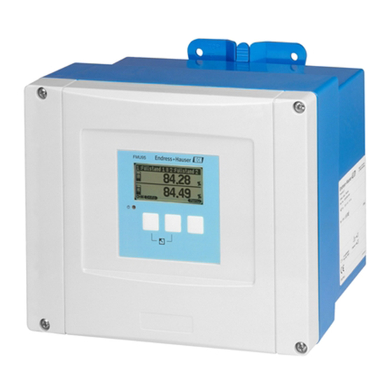
Transmitter for 5 or 10 ultrasonic sensors
Hide thumbs
Also See for Prosonic S FMU95:
- Description (76 pages) ,
- Operating instructions manual (86 pages) ,
- Operating instructions manual (108 pages)
Table of Contents
Advertisement
Quick Links
Brief Operating Instructions
Prosonic S FMU95
Transmitter for 5 or 10 ultrasonic sensors
These Instructions are Brief Operating Instructions; they do not replace the Opera-
ting Instructions included in the scope of supply.
For detailed information, refer to the Operating Instructions and other documenta-
tion on the CD-ROM provided or visit "www.endress.com/
deviceviewer".
KA01069F/00/EN/01.11
71145369
Advertisement
Table of Contents

Related Manuals for Endress+Hauser Prosonic S FMU95


Summary of Contents for Endress+Hauser Prosonic S FMU95
- Page 1 Brief Operating Instructions Prosonic S FMU95 Transmitter for 5 or 10 ultrasonic sensors These Instructions are Brief Operating Instructions; they do not replace the Opera- ting Instructions included in the scope of supply. For detailed information, refer to the Operating Instructions and other documenta- tion on the CD-ROM provided or visit "www.endress.com/...
-
Page 2: Table Of Contents
Prosonic S FMU95 PROFIBUS Table of contents Safety Instructions......... 3 Designated use . -
Page 3: Safety Instructions
FDU92, FDU93, FDU95 and FDU96. The sensors of the class FDU8x can be connected as well. Installation, commissioning, operation The Prosonic S FMU95 is fail-safe and constructed to the state-of-the-art. It meets the approp- riate standards and EC directives. However, if you use it improperly or other than for its desig- nated use, it may pose application-specific hazards, e.g. -
Page 4: Safety Icons
Mounting Prosonic S FMU95 PROFIBUS Safety icons Safety conventions Warning! A warning highlights actions or procedures which, if not performed correctly, will lead to personal injury, a safety hazard or destruction of the instrument Caution! " Caution highlights actions or procedures which, if not performed correctly, may lead to personal injury or... -
Page 5: Installation
Prosonic S FMU95 PROFIBUS Mounting Installation 2.2.1 Installation conditions of the field housing Weather protection In order to avoid excessive sunlight exposure, the instrument should be mounted in a position which is protected against direct sunlight or a protection cover should be applied. - Page 6 Mounting Prosonic S FMU95 PROFIBUS 2.2.2 Installation conditions of the DIN-rail housing • The DIN-rail housing must be mounted outside hazardous areas in a cabinet. • The housing is mounted on a DIN rail EN 60715 TH 35 x 7.5 or TH 37 x 15.
-
Page 7: Mounting The Remote Display And Operating Module
Prosonic S FMU95 PROFIBUS Mounting Mounting the remote display and operating module 2.3.1 Scope of delivery If the Prosonic S is ordered with the display for cabinet door mounting, the following is contained in the scope of delivery: • 4 retainers (with nuts and screws) → ä 8 "Mounting"... - Page 8 Mounting Prosonic S FMU95 PROFIBUS 2.3.3 Mounting L00-FMU90xxx-17-00-00-xx-002 Note! For more information and details, see the Operating Instructions BA00344F on the CD-ROM provided. 2.3.4 Adaption plate If an opening of 138 x 138 mm (5.43 x 5.43 in) and the remote display of the Prosonic FMU860/861/862 are already present, you can use the adaption plate (Order Code: 52027441).
-
Page 9: Mounting Of The Sensors
Prosonic S FMU95 PROFIBUS Mounting L00-FMU90xxx-06-00-00-xx-006 1 Remote display of the FMU90 with adaption plate 2 Remote display of the FMU860/861/862 Mounting of the sensors Information on the mounting of the sensors can be found in the following documents: • Technical Information TI00189F (for FDU8x) •... -
Page 10: Wiring
Wiring Prosonic S FMU95 PROFIBUS Wiring Warning! The instrument may only be installed if the supply voltage is switched off. Terminal compartment of the field housing The field housing has a separate terminal compartment. It can be opened after loosening the four screws of the lid. -
Page 11: Terminal Compartment Of The Din-Rail
Prosonic S FMU95 PROFIBUS Wiring 3.1.1 Cable entries of the field housing The following openings for cable entries are prestamped on the bottom of the housing: M20x1.5 (10 openings), M16x1.5 (5 openings), M25x1.5 (1 opening) The required number and types of cable entries depend on the application at hand. - Page 12 Wiring Prosonic S FMU95 PROFIBUS 3.2.2 Several instruments mounted side by side L00-FMU95KAx-04-00-00-xx-005 Endress+Hauser...
-
Page 13: Terminal Assignment
FDU-Sensor FDU-Sensor Sync Service Fuse Display L00-FMU95xxx-04-00-00-xx-003 Terminals of the Prosonic S FMU95; the terminals depicted in grey are not present in every instrument version. Terminals Meaning Remarks Auxiliary energy • L (for AC version) depending on instrument version: • L+ (for DC version) •... - Page 14 Wiring Prosonic S FMU95 PROFIBUS Terminals Meaning Remarks Level inputs 09,10,11 Sensor 1 (FDU8x/9x) 12, 13, 14 Sensor 2 (FDU8x/9x) YE: yellow strand 15, 16, 17 Sensor 3 (FDU8x/9x) BK: black strand RD: red strand 18, 19, 20 Sensor 4 (FDU8x/9x)
-
Page 15: Sensor Connection
Prosonic S FMU95 PROFIBUS Wiring Hinweis! • Information on the structure of a PROFIBUS DP network can be found in the Operating Instructions BA00034S ("PROFIBUS PA/DP - Guidelines for planning and commissioning". • For more information and details, see the Operating Instructions BA00344F on the CD-ROM provided. -
Page 16: Synchronization Line
Wiring Prosonic S FMU95 PROFIBUS Synchronization line • If wiring several Prosonic S (FMU90/FMU95) which are mounted in a common cabinet and if the sensor cables run in parallel, the FMU90 FMU90 FMU90 synchronization terminals (39 and 40) must be interconnected. -
Page 17: Connection Of The Separate Display And Operating Module
Prosonic S FMU95 PROFIBUS Wiring Connection of the separate display and operating module FDU-Sensor FDU-Sensor Sync Service Fuse Display L00-FMU95xxx-04-00-00-xx-008 1 Connection of the display plug with the cable (3 m (9.8 ft)) For the version of the Prosonic S with a separate display for panel mounting, a pre-assembled connecting cable (3 m (9.8 ft)) is supplied. - Page 18 Wiring Prosonic S FMU95 PROFIBUS Example FMU95 FDU-Sensor FDU-Sensor Sync Service Fuse Display GNYE GNYE FDU91F/93/95/96 FDU91F/93/95/96 90 … 253 VAC (FDU83/84/85/86) (FDU83/84/85/86) 10,5 … 32 VDC L00-FMU95xxx-04-00-00-xx-009 1 The wire is already connected on delivery Endress+Hauser...
- Page 19 Prosonic S FMU95 PROFIBUS Wiring 3.7.2 Potential equalization for the DIN-rail hosuing If the DIN-rail housing is used, the potential equalization must be connected in the cabinet, e.g. at a metallic DIN rail: Warning! The grounding line of the sensors FDU91F/93/95/96 and FDU83/84/85/86 must be connected to the local potential equalization system after a maximum of 30 m (98 ft).
-
Page 20: Post-Connection Check
Wiring Prosonic S FMU95 PROFIBUS " Caution! The signal evaluation electronics and its direct connections (display interface, service interface etc.) are galvanically isolated from the supply voltage and the communication signals. Their electric potential is identiacal to the potential of the sensor electronics. -
Page 21: Operation
Prosonic S FMU95 PROFIBUS Operation Operation Operating options • On-site operation via the display and operating module at the Prosonic S • Remote operation – Via the service interface with the Commubox FXA291 and the operating program FieldCare – Via PROFIBUS DP with the PROFIcard, PROFIboard or PROFIusb –... -
Page 22: Display Symbols
Operation Prosonic S FMU95 PROFIBUS Display symbols Symbol Meaning Operating mode of the instrument User User parameters can be edited. Service parameters are locked. Diagnosis The service interface is connected. Service User and service parameters can be edited. Locked All parameters are locked. - Page 23 Prosonic S FMU95 PROFIBUS Operation Keys (softkey operation) The function of the keys depends on the current position within the operating menu (softkey functionality). The key functions are indicated by softkey symbols in the bottom line of the display. Meaning...
- Page 24 Operation Prosonic S FMU95 PROFIBUS General key combinations The following key combinations do not depend on the menu position: Meaning Key combination Escape • While editing a parameter: Exit the editing mode without accepting the changes. • Within the navigation: Move upwards to the previous layer of the menu.
- Page 25 Prosonic S FMU95 PROFIBUS Operation 4.2.2 The operating menu Structure of the menu The parameters of the Prosonic S are organized in an operating menu (consisting of a main menu and several submenus). Parameters which are related to each other are comprised in a common parameter set.
-
Page 26: Commissioning
Commissioning Prosonic S FMU95 PROFIBUS Commissioning Setting the device address 5.1.1 Selecting the device address • Every PROFIBUS device must be given an address. If the address is not set correctly, the device will not be recognised by the process control system. -
Page 27: Bus Termination
Prosonic S FMU95 PROFIBUS Commissioning Hardware addressing comes into operation when DIP switch 8 is in the position "HW (OFF)". In this case the address is determinded by the position of DIP-switches 1 to 7 according to the following table: Switch No. -
Page 28: Loading The Device Database And Type Files (Gsd)
Commissioning Prosonic S FMU95 PROFIBUS Loading the device database and type files (GSD) 5.3.1 Meaning of the GSD files A device database file (GSD) contains a description of the properties of the PROFIBUS device, e.g. the supported transmission rates and the type and format of the digital information output to the PLC. -
Page 29: Basic Setup
Prosonic S FMU95 PROFIBUS Commissioning Basic setup After the first setup the main screen appears. However, the displayed value does not correspond to the real level before you have performed the basic setup. To do so, enter the main menu by pressing "Menu" (right key). - Page 30 Commissioning Prosonic S FMU95 PROFIBUS Step Parameter set Parameter Remarks → LVL N unit → unit level Select the unit for the level measurement. → level N (N = 1 - 5 or 10) (N = 1 - 5 or 10) Displays the currently measured level.
- Page 31 Prosonic S FMU95 PROFIBUS Commissioning Step Parameter set Parameter Remarks → LVL N dist. map. → act. distance N Indicates the currently measured distance bet- (N = 1 - 5 or 10) ween the reference point of the sensor and the product surface.
- Page 32 Commissioning Prosonic S FMU95 PROFIBUS 5.5.2 Application parameters Parameter Selection/Remarks "tank shape" Use this parameter to specify the tank shape of your application: Selection: • dome ceiling (→ A) • horizontal cyl. (→ B) • bypass (→ C) • stilling well (ultrasonic guide pipe) (→ C) •...
- Page 33 Prosonic S FMU95 PROFIBUS Commissioning "process conditions" for the following situations Example filter settings standard liquid for all fluid applications The filters and output damping are set which do not fit in any of the to average values. following groups...
- Page 34 Commissioning Prosonic S FMU95 PROFIBUS "process conditions" for the following situations Example filter settings solid dusty Dusty bulk solids The averaging filters are set to detect even relatively weak signals. conveyor belt Bulk solids with rapid level The averaging filters are set to small change values.
- Page 35 Prosonic S FMU95 PROFIBUS Commissioning 5.5.3 Empty and full calibration Parameter Remarks "empty calibration" Use this parameter to specify the empty distance E, i.e. the distance between the reference point of the sensor and the minimum level (zero point). "...
- Page 36 Commissioning Prosonic S FMU95 PROFIBUS 5.5.4 Linearization Parameter Selection/Remarks "type" Note! Number and type of the parameters in this set depend on the selected linearization type. Only the parameters "type" and "mode" are always present. Selection • none In this linearization type the measured level is not converted but displayed in the selected level unit (see "unit level").
- Page 37 Prosonic S FMU95 PROFIBUS Commissioning Parameter Selection/Remarks "type" In these linearization types the measured level is convertet to the volume in a horizontal cylinder or a spherical tank. Selection • horizontal cyolinder • sphere The following additional parameters have to be specified: •...
- Page 38 Commissioning Prosonic S FMU95 PROFIBUS Parameter Selection/Remarks "type" In this linearization mode the measured value is calculated from a linearization table. The table may consist of up to 32 pairs of values (level - volume). The table must be monoto- nically increasing or decreasing.
- Page 39 Prosonic S FMU95 PROFIBUS Commissioning Parameter Selection/Remarks The table editor Level Level Value Value 0,0000 0,0000 0,0000 0,0000 0,0000 0,0000 0,0000 0,0000 0,0000 0,0000 0,0000 0,0000 … … 0,0000 0,0000 0,0000 0,0000 : go to next row : navigate within the table : go to previous row : (for "Level"...
- Page 40 Commissioning Prosonic S FMU95 PROFIBUS 5.5.5 Interference echo suppression: Basic principles Parameter Remarks "check value" The "check value" and "distance mapping" parameters are used to configure the "distance mapping" interference echo suppression of the Prosonic S. The following picture shows the operating principle of the interference echo suppression:...
- Page 41 Prosonic S FMU95 PROFIBUS Commissioning Endress+Hauser...
- Page 42 Commissioning Prosonic S FMU95 PROFIBUS Endress+Hauser...
- Page 43 Prosonic S FMU95 PROFIBUS Commissioning Endress+Hauser...
- Page 44 KA01069F/00/EN/01.11 71145369 CCS/FM+SGML 9.0 71145369...