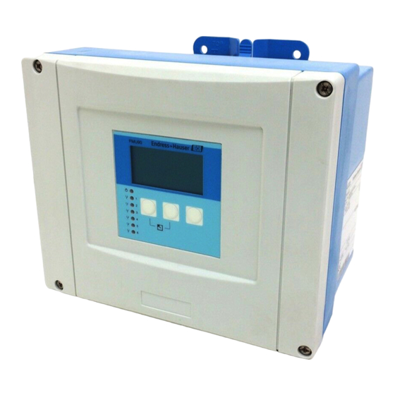
Endress+Hauser Prosonic S FMU90 Description
Ultrasonic transmitter; description of instrument functions
Hide thumbs
Also See for Prosonic S FMU90:
- Operating instructions manual (186 pages) ,
- Brief operating instructions (56 pages) ,
- Technical information (36 pages)
Table of Contents
Advertisement
Quick Links
Download this manual
See also:
Technical Information
Advertisement
Table of Contents

Related Manuals for Endress+Hauser Prosonic S FMU90


Summary of Contents for Endress+Hauser Prosonic S FMU90
- Page 1 Description of Instrument Functions Prosonic S FMU90 Ultrasonic Transmitter BA290F/00/en/01.08...
-
Page 3: Table Of Contents
Table of Contents Table of Contents Notes on use ....4 The "language" submenu ....138 The "password/reset"... -
Page 4: Theory Of Operation
Notes on use Notes on use Theory of operation 1.1.1 Display and operating elements FMU90 L00-FMU90xxx-07-00-00-xx-002 (a): name of the parameter; (b): value of the parameter, including unit; (c): display symbols; (d): softkey symbol; (e): LED indicating the operating state; (f): LEDs indicating the switching states of the relays; (g): keys... -
Page 5: Display Symbols
Notes on use Display symbols Symbol Meaning Operating mode of the instrument User User parameters can be edited. Service parameters are locked. Diagnosis The service interface is connected. Service User and service parameters can be edited. Locked All parameters are locked. Locking state of the currently displayed parameter Display parameter The parameter can not be edited in the current operating mode of the instrument. - Page 6 Notes on use Keys (softkey operation) The function of the keys depends on the current position within the operating menu (softkey func- tionality). The key functions are indicated by softkey symbols in the bottom line of the display. Symbol Meaning Move downwards Moves the marking bar downwards within a selection list.
-
Page 7: The Operating Menu
Notes on use Key combination Meaning Locking Locks the instrument against parameter changes. The instrument can only be unlocked again by the keys. 1.1.2 The operating menu Structure of the menu The parameters of the Prosonic S are organized in an operating menu (consisting of a main menu and several submenus). - Page 8 Notes on use Parameter types Display parameters Parameters for which the symbol is dis- played in the left bottom corner of the display module, are either locked or display-only para- meters. L00-FMU90xxx-07-00-00-en-041 Editable parameters Parameters, for which the symbol is dis- played in the left bottom corner of the display module, can be entered for editing by pressing The editing procedure depends on the type of...
- Page 9 Notes on use Navigation within the menu (Example) L00-FMU90xxx-19-00-00-en-050...
- Page 10 Notes on use Entering the menu The navigation always starts from the main screen (measured value display ). From there, the fol- lowing menus can be opened by the keys: FMU90 shortcut menu main menu daily counter* level tag marking flow envelope curve language...
- Page 11 Notes on use Selecting a submenu In the main menu, press W or V until the main menu required submenu is marked by the bar. Note! The symbols indicate that the selection list contains more items than can be displayed on the module. Press W or V several times, to mark one of the hidden items.
- Page 12 Notes on use Selecting a parameter By pressing U or T you can switch between the parameter sets of the current submenu. For each parameter set the values of all its parameters are displayed. In order to change one of the values, proceed as follows: Press U or T, until you have reached the required parameter set.
- Page 13 Notes on use Editing a parameter with selection list Press W or V, until the required option is marked by the bar (in the example: "turb. surface"). Note! The symbols indicate that the selection list contains more items than can be displayed on the module.
- Page 14 Notes on use Entering numbers and characters When you select a numeric parameter ("empty calibration", "full calibration" etc.) or an alpha- numeric parameter ("device marking" etc.), the editor for numbers and text strings appears. Enter the desired value in the following way: The cursor is at the first digit.
- Page 15 Notes on use Special editing functions Within the editor for alphanumeric characters, pressing S or O does not only lead to numbers and characters but also to the following symbols for special editing functions. They simplify the editing procedure. L00-FMU90xxx-19-00-00-yy-043 Enter: The number left of the cursor is transferred to the instrument.
- Page 16 Notes on use L00-FMU90xxx-19-00-00-yy-047 Delete: The current digit and all digits to its right are deleted. Return to the measured value display By pressing the left and middle keys FMU90 simultaneously you can return • from a parameter to the parameter set •...
-
Page 17: First Setup
Notes on use First setup Note! This chapter describes the commissioning of the Prosonic S via the display and operating module. Commissioning via ToF Tool, FieldCare or the HART handheld terminal DXR375 is similar. For further instructions refer to the ToF Tool Operating Instructions, the FieldCare Online Help or the Operating Instructions supplied with the DXR375. -
Page 18: The "Level" Menu
The "level" menu The "level" menu level LX001 "level" selection list ⇒ level (LVL) 1 Use this list to select the level channel you are going to configure. level (LVL) 2 The "basic setup" submenu 2.1.1 "LVL N sensor selection" (N = 1 or 2) LVL1 sensor sel. - Page 19 The "level" menu 2.1.2 "LVL N application parameters" (N = 1 or 2) LVL1 appl. para. L1004 ⇒ tank shape: medium property: process cond.: "tank shape" Use this parameter to specify the tank shape of your application. Selection: dome ceiling horizontal cyl bypass stilling well...
- Page 20 The "level" menu "process conditions" Use this parameter to specify the process conditions of your application. The filters of the signal evaluation are automatically adjusted to the selected conditions. "process conditions" for the following situations Example filter settings standard liquid for all fluid applications which do The filters and output damping are set not fit in any of the following...
- Page 21 The "level" menu 2.1.3 "LVL N empty calibration" (N = 1 or 2) LVL1 empty cal. L1005 ⇒ empty E: 0,00 m "empty E" Use this parameter to specify the empty distance E, i.e. the distance between the sensor membrane and the minimum level (zero point).
- Page 22 The "level" menu 2.1.4 "LVL N full calibration" (N = 1 or 2) LVL1 full calib. L1006 ⇒ full F: 0,00 m block.dist. BD: "full F" Use this parameter to specify the span F, i.e. the distance from the minimum level to the maximum level. 20 mA 100% –...
- Page 23 The "level" menu 2.1.5 "LVL N unit" (N = 1 or 2) LVL 1 unit L1007 ⇒ unit level: level 1: distance: "unit level" Use this parameter to select the level unit. If no linearization is performed, the level is displayed in this unit. Selection: •...
- Page 24 The "level" menu Note! The distance unit is defined during the first setup of the instrument. If required, it can be changed in the "device properties/operating params" menu. 2.1.6 "LVL N linearisation" (N = 1 or 2) LVL 1 linearisat. L1008 Note! ⇒...
- Page 25 The "level" menu • horizontal cylinder • sphere In these linearization types the measured level is convertet to the volume in a horizontal cylinder or a spherical tank. 100% kg, m 3 , ft 3 , … The following additional parameters have to be specified: –...
- Page 26 The "level" menu • table In this linearization mode the measured value is calculated from a linearization table. The table may consist of up to 32 pairs of values (level - volume). The table must be monotonically increasing or decreasing. 100% = kg,m 3 , ft 3 , ...
- Page 27 The "level" menu "customer unit" Use this parameter to select the desired unit for the linearized values (e.g. kg, m , ft , ...). This unit is only indicated on the display. It does not cause a conversion of the measured value. Note! After selecting the option "customer specific", the parameter "customized text"...
- Page 28 The "level" menu "edit" Use this parameter to enter, change or read a linearization table. There are the following options: • read: The table editor is opened. The existing table can be read but not changed. • manual: The table editor is opened. Table values can be entered and changed. •...
- Page 29 The "level" menu 2.1.7 Interference echo suppression: Basic principles The "check value" and "distance mapping" parameters are used to configure the interference echo suppression of the Prosonic S. The following picture shows the operating principle of the interference echo suppression: (a) (b) (a) (b) L00-FMU90xxx-19-00-00-yy-017...
- Page 30 The "level" menu 2.1.8 "LVL N check value" (N = 1 or 2) LVL1 check value L100B ⇒ act. distance 1: check distance: L100B LVL1 dist. corr. act. distance: D display display > D check distance: display < D display L00-FMU90xxx-19-00-00-de-016 "actual distance N"...
- Page 31 The "level" menu The Prosonic S changes to the "LVL N distance mapping" function, where you can define the required range of mapping. 2.1.9 "LVL N distance mapping" (N = 1 or 2) LVL1 dist.map. L100B ⇒ act. distance 1: range of mapping: start mapping: status:...
- Page 32 The "level" menu 2.1.10 "LVL N state" (N = 1 or 2) LVL1 state L100C ⇒ level 1: act. distance 1: status: "level N" (N = 1 or 2) Displays the currently measured level. "act. distance N" (N = 1 or 2) Dispalys the currently measured distance.
-
Page 33: The "Extended Calibration" Submenu
The "level" menu The "extended calibration" submenu 2.2.1 "LVL N distance mapping" (N = 1 or 2) Is identical to the "LVL N distance mapping" parameter set in the "basic setup" submenu, see above. 2.2.2 "LVL N check value" (N = 1 or 2) LVL1 check value L1017 ⇒... - Page 34 The "level" menu 2.2.5 "LVL N limitation" (N = 1 or 2) LVL1 limitation L1019 ⇒ limitation: upper limit: lower limit: "limitation" Use this parameter to specify if the measured value has a lower and/or upper limit. Selection: • off •...
- Page 35 The "level" menu 2.2.6 "LVL N external input 1" "LVL N external input 2" (N = 1 or 2) LVL1 ext. input1 L1020 ⇒ input 1: function: Note! These parameters are only available for instruments with external limit switches (FMU90-********B***). These parameters are used to allocate up to 2 external limit switches to the level channel (e.g.
-
Page 36: The "Simulation" Submenu
The "level" menu The "simulation" submenu 2.3.1 "LVL N simulation" (N = 1 or 2) LVL1 Simulation L1022 The parameters of this set are used to simulate a level or a measured ⇒ simulation: value in order to check the linearisation, the signal output and the (sim. -
Page 37: The "Flow" Menu
The "flow" menu The "flow" menu The "flow" submenu is used for the calibration of • flow measurements (1 or 2 channels) • back water alarm • flow counters The structure of the submenu depends on the selected operating mode operating modes operating mode “level+flow”... - Page 38 The "flow" menu 3.1.1 The "basic setup" submenu "flow N sensor selection" (N = 1 or 2) flow1 sensor sel. F1003 ⇒ input: sensor selection: detected: "input" Use this parameter to allocate a sensor to the channel. Selection • no sensor •...
- Page 39 The "flow" menu The "linearization" parameter set is used to calculate the flow from the measured level. The Prosonic S provides the following linearization types: • pre-programmed flow curves for commonly used flumes and weirs • a freely editable linearization table (up to 32 points) α...
- Page 40 The "flow" menu • read: The table editor appears. An existing table can be viewed but not changed. • manual: The table editor appears. Table values can be entered and changed. • delete: The linearization table is deleted. The table editor Level Value Level...
- Page 41 The "flow" menu "flow N empty calibration" (N = 1 or 2) flow 1 empty cal. F1010 empty E: 0,00 m ⇒ blocking dist. "empty E" Use this parameter to enter the empty distance E, i.e. the distance between the sensor membrane and the zero point of the flume or weir.
- Page 42 The "flow" menu Type of sensor blocking distance (BD) maximum measuring dis- tance FDU95 - *2*** (high temperature version) 0,9 m 45 m (for solids) FDU96 1,6 m 70 m (for solids) FDU80/FDU80F 0,3 m 5 m (for liquids) FDU81/81F 0,5 m 10 m (for liquids) FDU82...
- Page 43 The "flow" menu Interference echo suppressio: Basic principles The "flow N check value" and "flow N mapping" parameter sets are used to configure the inter- ference echo suppression of the Prosonic S. The following picture shows the operating principle of the interference echo suppression: (a) (b) (a) (b) L00-FMU90xxx-19-00-00-yy-030...
- Page 44 The "flow" menu "distance" Displays the currently measured distance D display "check distance" Use this parameter to state if the displayed distance D matches the real distance D. Based on display your selection, the Prosonic S automatically proposes a suitable range of mapping. You have got the following options: •...
- Page 45 The "flow" menu The "flow N state" parameter set appears, in which the currently measured level, distance and flow are displayed. Compare the displayed distance to the real distance in order to decide if a further mapping is necessary. If yes: Press the left-arrow key (←) in order to return to the "flow N mapping" parameter set. If no: Press the right key (→) in order to return to the "flow N"...
- Page 46 The "flow" menu 3.1.2 The "extended calibration" submenu "flow N mapping" (N = 1 or 2) flow 1 mapping F1010 ⇒ sensor: range of mapping: start mapping: status: Is identical to the "flow N mapping" parameter set in the "basic setup" submenu, see page 44. "flow N low cut off"...
- Page 47 The "flow" menu "flow N level correction" (N = 1 or 2) flow 1 level corr. F1013 ⇒ offset: flow 1: "offset" This parameter can be used to shift the level by a constant value. The level entered into this para- meter is added to the measured level.
- Page 48 The "flow" menu "lower limit" Defines the lower limit for the measured value. (only available for the options "low limit" and "low/high limit") 20mA 100% 0/4mA L00-FMU90xxx-19-00-00-yy-019 (1): lower limit; (2): upper limit (a): limitation switched off; (b): limitation switched on...
- Page 49 The "flow" menu "flow N external input 1" "flow N external input 2" (N = 1 or 2) flow1 ext. input1 L1020 ⇒ input 1: function: Note! These parameters are only available for instruments with external limit switches (FMU90-********B***). These parameters are used to allocate up to 2 external limit switches to the flow channel (e.g. one minimum safety and one maximum safety switch).
- Page 50 The "flow" menu 3.1.3 The "simulation" submenu "flow N simulation" (N = 1 or 2) flow 1 simulation F1020 The parameters of this set are used to simulate a level or a flow in ⇒ simulation: order to check the linearisation, the signal output and the connected (sim.
-
Page 51: The "Backwater" Submenu
The "flow" menu The "backwater" submenu 3.2.1 Basics The flow measurement can be impaired by backwater on the downstream side or by dirt within the flume. The backwater and dirt detection function can detect these errors and ensure that the Prosonic S reacts appropriately. - Page 52 The "flow" menu Note! • For the sensors FDU9x, the option "automatic" is recommended (default setting). With this setting the Prosonic S recognizes the type of sensor automatically. • For the sensors FDU8x, the type has to be assigned explicitly. The automatic sensor recognition does not work for these sensors.
- Page 53 The "flow" menu "backwater detection" backw. detection F1305 ⇒ ratio B: "ratio B" Use this parameter to specify the upper limit for the ratio h If during the measurement the ratio exceeds this limit, the backwater alarm becomes active, i.e.: •...
- Page 54 The "flow" menu h2/h1 > D h2/h1 < D L00-FMU90xxx-19-00-00-yy-036 "backwater" backwater F1307 ⇒ act. backw. level: act. flow level: actual ratio: flow 1: The following is displayed in this parameter set: • the current backwater level h (downstream level) •...
- Page 55 The "flow" menu You have got the following options: • distance = ok Choose this option if the displayed value matches the real distance. After selecting this option, the "backwater mapping" parameter set appears. The preset range of mapping is equal to D. That means: all interference echos which are above the current product surface will be mapped out in the interference echo suppression.
- Page 56 The "flow" menu "backwater status" backw. status F130A ⇒ act. backw. level: distance: flow 1: status: "actual backwater level" Displays the currently measured level of the backwater sensor. "distance" Displays the currently measured distance between the backwater sensor membrane and the liquid surface.
- Page 57 The "flow" menu 3.2.3 The "extended calibration" submenu "backwater mapping" backw. status F1500 ⇒ sens. val. backw.: range of mapping: start mapping: status: Is identical to the "backwater mapping" parameter set in the "basic setup" submenu, see above. "backwater distance correction" backw dist.
- Page 58 The "flow" menu "backwater limitation" backw limitation F1503 ⇒ limitation: upper limit: lower limit: "limitation" Use this parameter to specify if the measured downstream level has a lower and/or upper limit. Selection: • off • low limit • high limit •...
- Page 59 The "flow" menu "backwater external input 1" "backwater external input 2" backw.ext. input1 L1020 ⇒ input 1: function: Note! These parameters are only available for instruments with external limit switches (FMU90-********B***). These parameters are used to allocate up to 2 external limit switches to the backwater channel (e.g. one minimum safety and one maximum safety switch).
- Page 60 The "flow" menu 3.2.4 The "simulation" submenu "backwater simulation" backw simulation F1600 The parameters of this set are used to simulate a downstream water ⇒ simulation: level in order to check the parametrisation of the backwater and dirt (sim. level value:) detection.
-
Page 61: The "Flow Counter" Submenu
The "flow" menu The "flow counter" submenu flow counter F1100 ⇒ totaliser daily counter In this submenu, select which type of counter you are going to parametrize. Selection: • totaliser (not resettable) • daily counter (resettable) A selection of up to three totalisers or daily counters appears . - Page 62 The "flow" menu 3.3.1 "totalizer N/daily counter N" (N = 1 -3) totalizer 1 F1202 ⇒ allocation: counting unit: "allocation" Use this parameter to allocate a flow to the counter. Selection: • none (default) • flow 1, Q1 • flow 2, Q2 (for 2-channel instruments only) •...
- Page 63 The "flow" menu 3.3.2 "totalizer N/daily counter N" (N = 1 - 3) totalizer 1 F1203 ⇒ value: overflow: "value" Displays the current flow volume. "overflow" Whenever the counter passes the overflow, this parameter is incremented by 1. The total flow volume thus is: = overflow x 10 + value...
- Page 64 The "flow" menu 3.3.4 "daily counter N" (N = 1 - 3) daily counter 1 F1105 ⇒ external reset: externl start: Note! This parameter set is only available in instruments with external limit switches (FMU90-********B***). "external reset" This parameter allocates one of the external switch inputs to the counter by which it can be reset. Selection: •...
-
Page 65: The "Safety Settings" Menu
The "safety settings" menu The "safety settings" menu main menu CX001 ⇒ safety settings relay/controls output/calculat device properties "output on alarm" (only for HART instruments) output on alarm AX101 ⇒ output 1: output value 1: output 2: output value 2: 4.1.1 "output N"... -
Page 66: Output Echo Loss
The "safety settings" menu "output echo loss" outp. echo loss AX102 ⇒ level 1: level 2: Note! The parameter set "output echo loss" (AX102) is valid only for level measurements. For flow measurements there is an additional parameter set with a different code: "output echo loss" (AX112). -
Page 67: Delay Echo Loss
The "safety settings" menu 4.2.3 "value level N" or "value flow N" (N = 1 or 2) (only available for the option "customer specific") Use this parameter to specify the output value in the case of an echo loss. "delay echo loss" delay echo loss AX103 ⇒... -
Page 68: In Safety Distance
The "safety settings" menu "in safety distance" in safety dist. AX105 ⇒ in saf. dist. s 1: in saf. dist. s 2: 4.5.1 "in safety distance sensor N" (N = 1 or 2) Defines the reaction of the instrument if the level is in the safety distance. Selection: •... -
Page 69: Reaction High Temperature
The "safety settings" menu "reaction high temperature" react. high temp AX107 ⇒ overtemp sen 1: max. temp. Sen. 1: overtemp sen 2: max. temp. Sen. 2: 4.6.1 "overtemperature sensor N" (N = 1 or 2) Defines how the instrument reacts if the maximum temperature of the sensor is exceeded. Selection: •... -
Page 70: Relay Delay
The "safety settings" menu "relay delay" relay delay AX109 ⇒ startdelay relay: 4.8.1 "startdelay relay" Use this function to define a start delay for the relays of the Prosonic S. When the supply voltage is switched on, the relays do not switch immediately but one after another with the specified delay time in between. -
Page 71: The "Relays/Controls" Menu
The "relays/controls" menu The "relays/controls" menu The "relay configuration" submenu 5.1.1 "relay allocation" relay allocation RX101 ⇒ relay 1 relay 2 relay 3 relay 4 Use this parameter to select the relay you are going to configure. Selection: • All relays of the instrument version at hand Note! If a function has already been allocated to one of the relays, the name of this function is displayed next to the relay number. - Page 72 The "relays/controls" menu After selecting this option, a further selection list appears. Select the alarm to which the relay is allocated. Selection: – alarm relay the relay is energized if an "alarm" type error is detected. Continue by sections 5.1.7 and 5.1.11. –...
- Page 73 The "relays/controls" menu m, ft, m /h, ft /s, °C, m/min, ft/min, … m, ft, m /h, ft /s, °C, m/min, ft/min, … L00-FMU90xxx-19-00-00-yy-061 A: switch on point; B: switch off point; C: relay energized; D: relay de-energized • tendency/speed This limit type is similar to the "standard"...
- Page 74 The "relays/controls" menu m, ft, m /h, ft /s, °C, m/min, ft/min, … m, ft, m /h, ft /s, °C, m/min, ft/min, … L00-FMU90xxx-19-00-hfsdjhfjkdfkfhkf00-yy-062 1: "inband" limit relay; 2: "out of band" limit relay A: upper switching point; B: lower switching point; C: relay energized; D: relay de-energized; E: hysteresis "switch on point"...
- Page 75 The "relays/controls" menu 5.1.4 relay N (N = 1 - 6) (Parametrization of a time pulse relay) (only for instrument versions with flow functionality: FMU90 - *2********** and FMU90 - *4**********) relay 2 R2103 ⇒ function: time pulse pulse width: pulse time: "pulse width"...
- Page 76 The "relays/controls" menu "pulse value" Use this parameter to specify the flow volume after which a pulse is generated. Default: 100 m "pulse width" Use this parameter to specify the width of each pulse. Default: • HART: 200 ms • Profibus DP: 1000 ms Range of values: •...
- Page 77 The "relays/controls" menu m /h, ft /s, … m , ft , … 1 2 3 5 6 7 8 9 L00-FMU90xxx-19-00-00-yy-064 A: flow; B: pulse width; C: relay energized; D: relay de-energized; E: pulse value; F: pulse counter...
- Page 78 The "relays/controls" menu "start counter" and "stop counter" You can use these parameters to exclude very small and very large flows from being counted. If the flow is below "start counter" or above "stop counter" no pulses are generated. Both values are to be specified as a percentage of the maximum flow (Q •...
- Page 79 The "relays/controls" menu 5.1.8 "relay N" (N = 1 - 6) (Parametrization of a diagnostic relay) relay 2 R2103 ⇒ function: diagnostics allocation 1: allocation 2: "allocation 1/2" A specific instrument state or event can be allocated to each of these parameters. The relay is de- energized as soon as one of these states or events occurs.
- Page 80 The "relays/controls" menu 5.1.11 "relay N (N = 1 - 6)" (Relay behavior) relay X RX104 ⇒ switch delay: invert: error handling: "switch delay" (only available for limit relays) Use this parameter to specify the switch delay (in seconds). The relay does not switch immediately after the switch-on point has been exceeded but only after the specified delay.
- Page 81 The "relays/controls" menu The "pump control N" submenu - standard (N = 1 or 2) Note! Depending on the order code of the instrument, different functionalities can be configured for the pump control. The order code of the instrument can be found on the nameplate and in the operating menu at "system information/device information".
- Page 82 The "relays/controls" menu L00-FMU90xxx-19-00-00-yy-052 A: switch-on point; B: switch-off point; C: pump on; D: pump off Operating mode The Prosonic S can control several pumps simultaneously - depending on the number of relays (s. feature 70 of the product structure). If two or more pumps are applied for one level channel, you can choose between two different operating modes: Non-alternating pump control In this mode, each pump is switched according to the switching points allocated to it.
- Page 83 The "relays/controls" menu P1 P2 P3 P2 P3 L00-FMU90xxx-19-00-00-yy-053 1: Alternating pump control; that pump is switched on (switched off), which has been switched off (switched on) the longest time. 2: Non-alternating pump control; each switching point is allocated to a different pump. A: switch-on point of the pump;...
- Page 84 The "relays/controls" menu However, if the level is already near to the switch-off point (distance < switch-on barrier), no further pumps are swtiched on, even if the pump rate has not yet been achieved. P2 P3 P1+P2 L00-FMU90xxx-19-00-00-yy-054 A: switch-on point; B: switch-off point; C: pump on; D: pump off; E: hook-up interval; F: switch-on barrier G: pump rate Note! If both the alternating pump control and the pump rate contral are active, the pumps are alternately...
- Page 85 The "relays/controls" menu 5.2.2 Overview Parametrization of a pump control (type: limit control) Step Parameter set or submenu Parameter Remarks see section "relay/controls" menu Select "pump control1" or "pump control 2". pump control N reference Select the level according to which the pumps are controlled. 5.2.3 (N = 1 or 2) number of pumps...
- Page 86 The "relays/controls" menu Parametrization of a pump control (type: pump rate control) Step Parameter set or submenu Parameter Remarks see section "relay/controls" submenu Select "pump control 1" or "pump control 2". pump control N refernece Select the level according to which the pumps are controlled. 5.2.3 (N = 1 or 2) number of pumps...
- Page 87 The "relays/controls" menu • Range of values : 1 ... 6 (depending on the number of relays) • Default: 1 5.2.4 "pump control N" (N = 1 or 2) pump control R1301 ⇒ function: "function" Determines the type of pump control. Selection: •...
- Page 88 The "relays/controls" menu " Caution! After a change of the "unit level" the switch off point has to be checked and adjusted if required. "switch-on delay" Specifies the switch-on delay of the respective pump (in seconds). When the level has risen above the switch-on point, the relay does not switch immediately but only after the specified switch-on delay.
- Page 89 The "relays/controls" menu L00-FMU90xxx-19-00-00-yy-056 A: switch-on point; B: switch-off point; C: pump on; D: pump off; E: inaccuracy ("crust reduction") 5.2.7 "pump M/control N" (M = 1 - 6, N = 1 or 2) (Part 2: Switching behavior for limit control) pumpM/controlN RN304 ⇒...
- Page 90 The "relays/controls" menu L00-FMU90xxx-19-00-00-yy-057 A: switch-on point; B: switch-off point; C: pump on; D: pump off E: backlash interval; F: backlash time "error handling" This parameter defines the reaction of the relay in the case of an error. Selection: • hold (default) The current switching state of the relay is held.
- Page 91 The "relays/controls" menu 5.2.9 "relay N" (N = 1 - 6) relay N RN306 ⇒ function: invert: "function" Allocates the desired function to the relay. Selection: • none (default) • pump M/control N "invert" Determines if the switching behavior of the relay is inverted. Selection: •...
- Page 92 The "relays/controls" menu "crust reduction" subfunction Specifies a range of inaccuracy (percentage of the measuring range) for the switching points. If this value is larger then "0", the switching points are not exactly constant. Instead, they vary within the specified range of inaccuracy. This helps to avoid crust formation, which often occurs at fixed switching points.
- Page 93 The "relays/controls" menu 5.2.11 "pump M/control N (M = 1 - 6, N = 1 or 2) (Switching behavior for rate control) pump control RN304 ⇒ switch-on delay: backlash interval: backlash time: error handling: "switch-on delay" see page 88 "backlash interval" and "backlash time" see page 89 "error handling"...
- Page 94 The "relays/controls" menu The "pump control N" submenu - enhanced (N = 1 or 2) Note! Depending on the order code of the instrument, different functionalities can be configured for the pump control. The order code of the instrument can be found on the nameplate and in the operating menu at "system information/device information".
- Page 95 The "relays/controls" menu Note! If several pumps are allocated to a pump control, the switching direction of all these pumps must be the same. Mixing of "filling" and "emptying" is not allowed. The difference between "limit simple" and "limit parallel" relates to the control of more than one pump: •...
- Page 96 The "relays/controls" menu Function "pump rate control" If pump rate control has been selected, there is only one switch-on point and one switch-off point, which are valid for all relays. Additionally, a desired pump rate has to be specified. If the level rises above (or falls below) the switch-on point, initially only one pump is switched on. If the desired pump rate has not been achieved after the selected hook-up interval, an additional pump is switched on.
-
Page 97: Basic Setup
The "relays/controls" menu 5.3.2 Basic setup Overview: Parametrization of a limit control (simple/parallel) Step Parameter set or submenu Parameter Remarks see page "relay/controls" menu 1. Select "pump control1" or "pump control 2". 2. Select "basic setup". pump control N reference Select the level according to which the pumps are controlled. - Page 98 The "relays/controls" menu Overview: Parametrization of a pump rate control Step Parameter set or submenu Parameter Remarks see section "relay/controls" submenu Select "pump control 1" or "pump control 2". pump control N reference Select the level according to which the pumps are controlled. (N = 1 or 2) number of pumps Select the number of pumps.
- Page 99 The "relays/controls" menu "pump control N" (N = 1 or 2) pump control R1401 ⇒ reference: number of pumps: standby pump: reset: "reference" Defines the level channel to which the pump control refers. Selection: • none (default) • level 1 •...
- Page 100 The "relays/controls" menu "pump control N" (N = 1 or 2) pump control R1402 ⇒ function: load control: "function" Determines the type of pump control. Selection: • limit parallel (Default) Each pump has its own switch-on point and switch-off point. Several pumps can be running at the same time.
- Page 101 The "relays/controls" menu "pump M/control N" (M = 1 - 6; N = 1 or 2) (Part 1: Switching points for limit control) pump 1/control 1 R1303 ⇒ switch on point: switch off point: switch on delay: crust reduction: "switch on point" Specifies the switch-on point of the respective pump.
- Page 102 The "relays/controls" menu "alternate" Specifies if the pump should be included in the alternating pump control. Selection • no (default) The pump is not included in the alternating pump control. Instead, it switches according to its own switch points. • yes The pump is included in the alternating pump control.
- Page 103 The "relays/controls" menu "pump M/control N" (M = 1 - 6, N = 1 or 2) (Part 2: Switching behavior for limit control) pumpM/controlN RN304 ⇒ backl. interval: backlash time: error handling: "backlash interval" and "backlash time" Use these parameters if you want to empty a vessel beyond the switch-off point in regular intervals. The "backlash interval"...
- Page 104 The "relays/controls" menu "pump M/control N" (M = 1 - 6, N = 1 or 2) (Part 3: Parametrization of the associated switch inputs) pumpM/control N R1406 ⇒ pump feedback: feedback delay: feedback meaning: Note! This parameter exists only for intruments with external limit switches. "pump feedback"...
- Page 105 The "relays/controls" menu "relay allocation" relay allocation RN305 ⇒ relay 1 relay 2 relay 3 relay 4 Allocates a relay to the pump. Selection: • All relays of the instrument version at hand "relay N" (N = 1 - 6) relay N RN306 ⇒...
- Page 106 The "relays/controls" menu "pump control N" (N = 1 or 2) (Switching points for rate control) pump control R13A3 ⇒ switch on point: switch off point: min pump rate: alternate: "switch on point" Specifies the switch-on point. Use the selected level unit. "...
- Page 107 The "relays/controls" menu "switch on border" Specifies the switch-on border for the rate control (for details see section "limit control and rate control"). "hook up interval" Specifies the time interval between the switching-on of the different pumps (for details see section "limit control and rate control").
- Page 108 The "relays/controls" menu 5.3.3 The "storm function" submenu The storm function is used to avoid unnecessary running of the pump if the plant is flooded for a short time (e.g. in the case of strong rainfall). "storm function N" ( N = 1 or 2) storm function 1 R13A3 ⇒...
- Page 109 The "relays/controls" menu 5.3.4 The "function test" submenu The function test is used to avoid incrustations which may occur if pumps are switched off for a long time. If a pump has not been running for a defined time (max downtime), it is automatically switched on for a short time (max test time).
- Page 110 The "relays/controls" menu 5.3.5 The "flush control" submenu The flush control is used to switch a pump on for a number of cycles (flush cycles) for a defined time (flush time). This switching-on takes place within the defined number of pump cycles. The figure below shows an example with 5 pump cycles and 2 flush cycles.
- Page 111 The "relays/controls" menu "relay allocation" relay allocation RX604 ⇒ relay 1 relay 2 relay 3 relay 4 Defines which relay is the flush relay. Selection: • All relays of the instrument version at hand. "relay N" (N = 1 - 6) relay N RN605 ⇒...
- Page 112 The "relays/controls" menu 5.3.6 The "tariff control" submenu Note! The tariff control is only available for instruments with external limit switches (FMU90-********B***). The tariff control allows to define two different switch-on and switch-off points for each pump. An external switch determines which of these switching points are currently valid. By connecting a time switch to the Prosonic S this allows to use low priced tariff times preferentially for pumping.
- Page 113 The "relays/controls" menu "tariff ctrl N pump M" (N = 1 or 2, M = 1 - 6) tariff ctr. 1 p1 R1608 ⇒ switch on point: switch on point: switch off point: switch off point: "switch on point" Displays the switch on point which is valid as long as no signal is present at the tariff switch input. (Is equal to the switch-on point defined in the basic setup.) "switch on point tariff"...
- Page 114 The "relays/controls" menu 5.3.7 The "pump data" submenu The most important operating data of the pumps can be displayed in this submenu. "pump data N" (N = 1 or 2) (pump selection) pump data 1 R1610 ⇒ pump 1: pump 2: Select a pump from this list.
- Page 115 The "relays/controls" menu reset backlash starts Resets the number of backlash starts to 0. Selection: • no "backlash starts" keeps its value. • yes "backlash starts" is reset to 0. last run time Indicates how long the pump has been running since the last switch-on.
- Page 116 The "relays/controls" menu 5.3.8 The "operating hours alarm" submenu A maximum run time can be defined for each pump. The operating hours alarm becomes active as soon as this run time is exceeded. "operating hours alarm N" (N = 1 or 2) op.hours alarm1 R1612 ⇒...
- Page 117 The "relays/controls" menu Note! The alarm is deactivated by a reset of the operating hours in the "pump data" submenu (e.g. after the maintenance of the pump has been completed). "relay allocation" relay allocation RX614 ⇒ relay 1 relay 2 relay 3 relay 4 Defines a relay which is associated with the operating hours alarm.
- Page 118 The "relays/controls" menu 5.3.9 The "pump alarm" submenu Note! This submenu is only available for instruments with external switches (FMU90-********B***). The pump alarm is used to indicate a pump failure by one of the relays. This is only possible if a pump monitoring system is connected to one of the switch inputs and if "pump feedback"...
-
Page 119: The "Rake Control" Submenu
The "relays/controls" menu The "rake control" submenu Note! The "rake control" submenus is only present if "rake control" has been selected in "device properties/operating parameters/controls". 5.4.1 Basics In order to detect clogging of a rake, the Prosonic S measures the upstream level L1 and the downstream leve L2. - Page 120 The "relays/controls" menu 5.4.3 "rake control" (Part 1: Allocation) rake control R1200 ⇒ upstream water: downstream water: function: "upstream water" Specifies, which signal refers to the upstream level. Selection: • level 1 (default) • level 2 "downstream water" Specifies, which signal refers to the downstream level. Selection: •...
- Page 121 The "relays/controls" menu L1 - L2 L00-FMU90xxx-19-00-00-yy-059 A: switch on point; B: switch off point; C: relay energized (i.e. rake cleaning on); D: relay de-energized (i.e. rake cleaning off)
- Page 122 The "relays/controls" menu function = "ratio" In this case, the switch on and switch off points are numbers between 0 and 1. The switch on point must be smaller than the switch off point. The rake control relay is energized if the ratio L2/L1 falls below the switch on point. It is de- energized if the ratio rises above the switch off point.
- Page 123 The "relays/controls" menu Selection: • actual value (default) The relay switches according to the current measuring value (although its reliability is not ensured). • hold The current switching state of the relay is held. • switch on The relay is energized. •...
-
Page 124: The "Relay Simulation" Submenu
The "relays/controls" menu The "relay simulation" submenu 5.5.1 "relay simulation" relay simulation RX120 In this list, select the relay you are going to simulate. ⇒ relay 1 relay 2 relay 3 relay 4 5.5.2 "relay N" (N = 1 - 6) relay 2 R2106 ⇒... - Page 125 The "output/calculations" menu (for HART instruments) The "output/calculations" menu (for HART instruments) main menu CX001 ⇒ output/calculat device properties system informat. The "output/calculations" menu can be used to • configure calculations such as averaging and subtraction • configure the current outputs and the HART interface. After entering the "output/calculations"...
-
Page 126: The "Allocation/Calculations" Submenu
The "output/calculations" menu (for HART instruments) The "allocation/calculations" submenu 6.1.1 "allocation current N " (N = 1 or 2) allocat. curr. 1 O1201 ⇒ output: output current: "output" Allocates a measured or calculated value to the current output. Selection: The available options depend on the instrument version, the connected sensors and the instrument configuration. - Page 127 The "output/calculations" menu (for HART instruments) The "extended calibration" submenu 6.2.1 "mode current N" (N = 1 or 2) mode current 1 OX202 ⇒ current span: output damping: 4mA threshold: curr. turn down: "current span" Used to select the current span to which the measuring range is mapped. Selection: •...
- Page 128 The "output/calculations" menu (for HART instruments) "output damping" Specifies the output damping τ by which changes of the measured value are attenuated. After a surge in the level it takes 5 x τ until the new measured value is reached. •...
- Page 129 The "output/calculations" menu (for HART instruments) "current turn down" (not present for "current span" = "fixed current HART") Used to map only a part of the measuring range to the current output. The selected part is enlarged by this mapping. "turn down 0/4 mA"...
- Page 130 The "output/calculations" menu (for HART instruments) "HART settings" submenu (only for current output 1) 6.3.1 "HART settings" HART settings O1203 ⇒ HART address: no. of preambles: short TAG HART: "HART address" Defines the communication address for the instrument. Range of values: •...
- Page 131 The "output/calculations" menu (for HART instruments) 6.3.2 "additional HART value 2/3/4" add. HART value2 O2205 ⇒ measured value 2: output 2: output damping: Use these parameter sets to configure the additional values transmitted by the HART protocol: • measured value 2 •...
-
Page 132: Simulation" Submenu
The "output/calculations" menu (for HART instruments) 5 x τ L00-FMG60xxx-05-00-00-xx-012 1: measured value; 2: HART output value "Simulation" submenu 6.4.1 "simulation" simulation O1204 ⇒ simulation: simulation value: "simulation" Used to switch on the simulation of the current. Selection: • off (default) No simulation is performed. -
Page 133: The "Output/Calculations" Menu (For Profibus Dp Instruments)
The "output/calculations" menu (for Profibus DP instruments) The "output/calculations" menu (for Profibus DP instruments) main menu CX001 ⇒ output calculat. device properties system information The "output/calculations" menu is used to configure the Analog Input blocks (AI) and the Digital Input blocks (DI). These blocks transfer analog or digital values to a SPS. "analog input"... -
Page 134: Digital Input" (Di)
The "output/calculations" menu (for Profibus DP instruments) "digital input" (DI) output/calculat. 01000 ⇒ analog input digital input Profibus DP 7.2.1 "output calculations" output/calculat. 0XB01 ⇒ digital input 1 digital input 2 digital input 3 digital input 4 Use this list to select the DI block you are going to configure. 7.2.2 "digital input N"... -
Page 135: Profibus Dp
The "output/calculations" menu (for Profibus DP instruments) "Profibus DP" output/calculat. 01000 ⇒ analog input digital input Profibus DP This submenu is used to configure the general properties of the Profibus DP interface. 7.3.1 "Profibus DP" Profibus DP O1C01 ⇒ profile version: instrument addr.: ident number: "profile version"... -
Page 136: The "Device Properties" Menu
The "device properties" menu The "device properties" menu The "operating parameters" submenu 8.1.1 "distance unit" distance unit D1101 ⇒ distance unit: Defines the distance unit. Selection: • m (default) • ft • mm • inch 8.1.2 "temperature unit" temperature unit D110B ⇒... -
Page 137: The "Tag Marking" Submenu
The "device properties" menu 8.1.4 "controls" controls D110D ⇒ controls: (only available for the "level" and "level + flow" operating modes) Use this parameter to specify which controls the Prosonic S is to perform. Selection: • no (default) • pump control •... -
Page 138: The "Language" Submenu
The "device properties" menu The "language" submenu 8.3.1 "language" language D1103 ⇒ langauge: Defines the language for the display module. The feature "language" of the procduct structure deter- mines which languages are available: "language" = 1: • Deutsch • English •... -
Page 139: The "Password/Reset" Submenu
The "device properties" menu The "password/reset" submenu" 8.4.1 "password/reset" password/reset D1104 ⇒ reset: code: status: "reset" Enter the reset code into this parameter in order to reset all parameters to their default values. Reset Code • HART: 333 • Profibus DP: 33333 Note! •... -
Page 140: The "System Information" Menu
The "system information" menu The "system information" menu The "device information" submenu 9.1.1 "device family" device family IX101 ⇒ device family: "device family" Displays the device family. 9.1.2 "device name" device IX102 ⇒ device name: "device name" Displays the device name. 9.1.3 "order code"... - Page 141 The "system information" menu "serial no." Displays the serial number of the instrument. 9.1.5 "software version" software version IX106 ⇒ software version: "software version" Displays the software version of the instrument. 9.1.6 "device version" dev. version IX107 ⇒ dev. rev.: "dev.
-
Page 142: The "In/Output Info" Submenu
The "system information" menu The "in/output info" submenu 9.2.1 "level (LVL) N" (N = 1 or 2) level (LVL) 1 IX107 ⇒ input: sensor selection: detected: "input" Indicates, which sensor input is connected to the level channel. "sensor selection" Displays the type of the connected sensor. For the sensors FDU9x, "automatic" is displayed, as these sensors are automatically detected by the transmitter (They have not to be spedified by the user.) "detected"... - Page 143 The "system information" menu 9.2.3 "current output N" (N = 1 or 2) (for HART instruments only) current output 1 IX10A ⇒ output: "output" Displays the present value of the output current. 9.2.4 "relay N" (N = 1 ... 6) relay 1 IX10B ⇒...
- Page 144 The "system information" menu The "trend display" submenu (for HART instruments only) Use this submenu to plot the temporal change of an output value. 9.3.1 "trend display" (for HART instruments only) trend display IX10E From this list, select the output you are going to plot. ⇒...
-
Page 145: The "Min/Max Values" Submenu
The "system information" menu The "min/max values" submenu Use this submenu to display the minimum and maximum values a certain parameter has reached during the measurement (drag indicator functionality). L00-FMU90xxx-19-00-00-yy-074 (1): max value; (2): min value; (3): measured value; (4): reset 9.4.1 "min/max values"... - Page 146 Note! • The min/max values of the sensor temperature can only be reset by the Endress+Hauser service. • The min/max values of the temperature always refer to the internal temperature probe of the ultrasonic sensors FDU8x/FDU9x.
-
Page 147: The "Envelope Curve" Submenu
The "system information" menu The "envelope curve" submenu This submenu can be used to display the envelope curve of the connected sensor on the display module. 9.5.1 "envelope curve" envelope curve IX126 In this list, select a sensor for the envelope curve display. ⇒... -
Page 148: The "Error List" Submenu
The "system information" menu 9.5.4 "envelope curve" envelope curve IX128 The envelope curve is displayed in this screen. ⇒ In order to exit the display, press the left and middle key simultaneously (ESC). The "error list" submenu 9.6.1 "error list" error list E1000 From this list, select if the currently active errors or the previous... -
Page 149: The "Diagnsotics" Submenu
The "system information" menu The "diagnsotics" submenu 9.7.1 "operating hours" operating hours E1403 ⇒ operating hours: "operating hours" Indicates, how long the instrument has been in operation. 9.7.2 "actual distance" actual distance E1404 ⇒ act. distance 1: act. distance 2: "act. - Page 150 The "system information" menu 9.7.4 "application parameter" appl. parameter E1405 ⇒ sensor 1: sensor 2: "sensor N" (N = 1 or 2) Indicates if a setting which depends on the application parameters ("tank shape", "medium property", "process condition") has been changed after the setting of the application parameters in the service menu.
-
Page 151: The "Display" Menu
The "display" menu The "display" menu 10.1 "display" calibr. display DX202 ⇒ type: time: value 1: cust. text 1: "type" Use this parameter to select the format of the measured value display. Selection: • 1x value+bargraph (default for instruments with 1 current output) •... -
Page 152: Display Format
The "display" menu "time" This parameter is used for the options "value max. size" and "alter 3x2 values". It specifies the time after which the next page appears. Note! To change to the next page immediately, press "value 1" ... "value 6" Use these parameters to allocate a measured or calculated value to each of the display values. -
Page 153: Back To Home
The "display" menu Determines if "text 1" to "text 6" from the "calibration display" parameter set are displayed. Selection: • no (Default) • yes 10.3 "back to home" back to home DX200 ⇒ back to home: "back to home" Use this parameter to specify the return time. If no entry is made during the specified time, the display returns to the measured value display. -
Page 154: The "Sensor Management" Menu
The "sensor management" menu The "sensor management" menu 11.1 The "sensor management" submenu input DX019 ⇒ FDU sensor 1: (FDU sensor 2:) Upon entering this menu, a selection list appears, from which you can select a sensor for parametrization. 11.1.1 "US sensor N"... - Page 155 The "sensor management" menu "sensor priority" (only for 2-channel instruments) This parameter is used to define the sensor priority. A sensor with high priority sends pulses more often than a sensor with low priority. Example (S1) (S2) priority sensor 1: 1 priority sensor 2: 1 ⇒...
- Page 156 The "sensor management" menu "detection window" Is used to switch the detection window on and off and to reset an existing detection window. If this function is switched on, a window is defined surrounding the current level echo (typical width: 1 to 2.5 m; depending on the application parameters). The window always moves togehter with a rising or falling echo.
- Page 157 The "sensor management" menu 11.1.2 "US sensor N" (N = 1 or 2) (allocation of external inputs) US sensor 1 D1107 ⇒ temp. measurement: ext. sens. ctrl.: input: distance: Note! This submenu is only available for instruments with external inputs (FMU90-********B***).
- Page 158 The "sensor management" menu "distance" (only for "external sensor control" = "value") Defines the distance value if an signal is active at the external switch input.
-
Page 159: The "External Temperature Sensor" Submenu
The "sensor management" menu 11.2 The "external temperature sensor" submenu Note! This submenu is only available for instruments with external temperature input (FMU90-********B***). 11.2.1 "external temperature sensor" (parametrization) ext.temp. sensor D1020 ⇒ sensor type: temperature unit: "sensor type" Defines the type of the connected sensor. Selection: •... - Page 160 The "sensor management" menu "reset" Is used to reset the index pointers for the external temperature sensor. Selection: • keep (default) The index pointers are not reset. • delete Both index pointers are reset to the current temperature. • reset min. "min.
-
Page 161: The "External Digin" Submenu
The "sensor management" menu 11.3 The "external digin" submenu external digin DX019 ⇒ external digin 1: external digin 2: external digin 3: external digin 4: Note! This submenu is only available for instruments with external switches (FMU90-********B***). After entering this submenu, select the external switch input you are going to configure. 11.3.1 "external digin N"... -
Page 162: Operating Menu
Operating menu Operating menu 12.1 "Level" main menu LX001 level level … L1002 level (LVL) 1 level (LVL) 1 level (LVL) 2 L1003 L1004 L1005 L1006 basic setup LVL1 sensor sel. LVL1 appl. para. LVL1 full calib. LVL1 empty cal. input: tank shape: empty E:... - Page 163 Operating menu L1008 L1007 L100B LVL1 unit LVL1 linearisat. LVL 1 check value customer unit: unit level: type: act. distance: % (default) check distance: none - dist. too big … … - dist. unknown L100B mode: level 1: - distance = ok LVL1 dist.
-
Page 164: Flow
Operating menu 12.2 "Flow" main menu F0000 F0001 flow flow flow … flow flow 1 flow 2 F1002 flow 1 F1003 basic setup flow1 sensor sel. input: sensor selection: detected: F1002 flow 1 F1013 F1010 F1011 F1012 extended calibr. flow1 level corr. flow1 mapping flow1 low cut off flow1 dist. - Page 165 Operating menu F1004 F1010 F1005 F1006 flow1 empty cal. flow1 flow1 linearizat. flow1 check value type: empty E: distance: flow1. flow unit: check distance: level: (curve:) - dist. too big sensor: (width:) - dist. unknown F1008 (edit:) - distance = ok flow1 mapping (status table:) - dist.
-
Page 166: Safety Settings
Operating menu 12.3 "Safety settings" main menu AX101* AX102 AX103 AX104 safety settings output on alarm outp. echo loss delay echo loss safety distance … output 1: level 1: delay sensor 1 saf. dist. sen 1 min. hold Default: 30s Default: 0,0 m max. - Page 167 Operating menu AX105 AX107 AX108 A0000 in safety dist. react. high temp def. temp. sensor relay delay startdelay relay in saf.dist. s 1 overtemp. sen 1 def. temp.sens 1: warning Default: 5s warning warning self holding alarm alarm alarm (max.temp. Sen. 1:) (def.temp.
-
Page 168: Relay/Controls
Operating menu 12.4 "Relay/Controls" 12.4.1 Pump control - standard (FMU90-*1********** und FMU90-*2**********) main menu R1001 relay/controls relay/controls … R1300 R1301 R1302 pump control 1 pump control 1 pump control 1 pump control 1 (pump control 2) R1303 reference: function: pump 1 pump 1 control 1 none pump... - Page 169 Operating menu R1304 RX305 pump 1 control 1 relay allocation relay 1: backl. interval: R1306 relay 2: default: 0 h relay 2 … backlash time: function: default: 0 s none error handling: pump 1 control 1 hold … switch on invert switch off actual value...
- Page 170 Operating menu 12.4.2 Pump control - enhanced: Basic setup (FMU90-*3********** and FMU90-*4**********) main menu R1001 relay/controls relay/controls … R1400 pump control 1 pump control 1 (pump control 2) R1401 R1402 basic setup pump control 1 pump control 1 reference: function: none limit parallel R1403...
- Page 171 Operating menu R1405 R1406* RX407 pump 1 control 1 pump 1 control 1 relay allocation relay 1: backl. interval: pump feedback: R2408 relay 2: default: 0 h disabled relay 2 … backlash time: ext. digin 1 function: default: 0 s keine error handling: ext.
- Page 172 Operating menu 12.4.3 Pump control - enhanced: additional functions (FMU90*3********** and FMU90-*4**********) R1400 pump control 1 R1601 storm function storm function 1 storm function: switch on point: switch off point: storm time: 60 min R1400 pump control 1 R1602 function test function test 1 function test: max downtime:...
- Page 173 Operating menu...
- Page 174 Operating menu 12.4.4 Rake control/Relay configuration/Simulation R1001 relay/controls rake control R1200 R1201 R1202 RX203 rake control rake control rake control relay allocation upstream water: switch on point: switch delay: relay 1: R2204 none default: 20% / 0.8 default: 0 s relay 2: relay allocation level 1...
- Page 175 Operating menu R2103 R2104 R2103 R2104 relay 2 relay 2 relay 2 relay 2 function: switch delay: limit: switch delay: limit xxxx default: 0 s limit xxxx default: 0 s limit type: limit type: invert. invert: inband/out of bd. standard switch on point: upper switchpt.: default: 60%...
-
Page 176: Output/Calculations
Operating menu 12.5 "Output/calculations" (HART) main menu OX001 output/calculat output/calculat … O1302 current output 1 current oputput 1 (current output 2) O1201 allocat./calculat allocat. curr. 1 output: level 1 ..flow 1 … average level … output current: O1302 current output 1 OX202 extended calibr. -
Page 177: Output/Calculations" (Profibus Dp)
Operating menu 12.6 "Output/calculations" (Profibus DP) main menu O1000 output calculat. output/calculat … OXA01 analog input output/calculat. O1A02 analog input 1 analog input 1 O1A02 measured value 1: analog input 10 output value: status: none level 1 flow 1 average level OXB01 digital input output/calculat... -
Page 178: Device Properties
Operating menu 12.7 "Device properties" main menu D1001 device properties device properties … D110D D1101 D110B D110C operating param. controls distance unit temperature unit operating mode distance unit: temperature unit: operating mode: controls: °C level °F level+flow pump control flow rake controle inch flow+backwater... - Page 179 Operating menu...
-
Page 180: System Information
Operating menu 12.8 "System information" main menu IX001 system informat. system informat. … IX101 IX102 IX103 IX105 device information device family device order code serial no. device family: device name: order code: serial no.: IX108 IX108 IX109 IX109 IX10A* in/output info level (LVL) 1 level (LVL) 2 flow 1... - Page 181 Operating menu IX106 IX107 IX108 software version dev. version DD version software version: dev. rev.: DD version: IX11A* IX10B IX10B … relay 1 relay N current output 2 output: function: function: * only for HART instuments L00-FMU90xxx-19-07-02-en-106...
-
Page 182: Display
Operating menu 12.9 "Display" main menu DX202 DX201 DX200 display display display format back to home … type: format: back to home: 1xvalue + bargr. decimal default: 900 s … ft-in-1/16" (value 1:)* no. of decimals: (cust. text 1:)* default: x.xx …... -
Page 183: Appendix
Appendix Appendix 13.1 Pre-programmed flow curves 13.1.1 Khafagi-Venturi flumes L00-FMU90xxx-05-00-00-xx-004 BD: blocking distance of the sensor Type of flume [mm] [mm] [mm] Khafagi-Venturi QV 302 40,09 Khafagi-Venturi QV 303 104,3 Khafagi-Venturi QV 304 231,5 Khafagi-Venturi QV 305 323,0 Khafagi-Venturi QV306 414,0 Khafagi-Venturi QV 308 1024... - Page 184 Appendix The pre-programmed curves can also be used for Khafagi-Venturi flumes with elevated walls. To do so, Q has to be adjusted ("linearization" function, "max. flow" subfunction): Type of flume [mm] Khafagi-Venturi QV 302 81,90 Khafagi-Venturi QV 303 187,9 Khafagi-Venturi QV 304 359,9 Khafagi-Venturi QV 305 637,7...
- Page 185 Appendix 13.1.2 ISO-Venturi flumes ³ 3 H L00-FMU90xxx-05-00-00-xx-004 BD: blocking distance of the sensor Type of flume [mm] [mm] [mm] ISO-Venturi 415 42,5 ISO-Venturi 425 130,3 ISO-Venturi 430 322,2 ISO-Venturi 440 893,6 ISO-Venturi 450 1318,9 ISO-Venturi 480 2200 Note! After selecting the type of flume, Q can be adjusted to the flow conditions.
- Page 186 Appendix 13.1.3 British standard Venturi flumes (BS 3680) ≥ 3 H ≥ 3 (B-b) L00-FMU90xxx-05-00-00-xx-005 BD: blocking distance of the sensor The bottom of the flume may not have any slope throughout the length x. (no measuring flume with data threshold) Type of flume [mm] BST Venturi 4"...
- Page 187 Appendix 13.1.4 Parshall flumes 2/3 A L00-FMU90xxx-05-00-00-xx-006 BD: blocking distance of the sensor A: horizontal bottom of the channel Type of flume [mm] Parshall 1" 1" 15,23 Parshall 2" 2" 30,46 Parshall 3" 3" 204,2 Parshall 6" 6" 430,5 Parshall 9" 9"...
- Page 188 Appendix 13.1.5 Palmer-Bowlus flumes 30° 30° L00-FMU90xxx-05-00-00-xx-007 Type of flume [mm] Palmer-Bowlus 6" 6" 38,08 Palmer-Bowlus 8" 8" 68,86 Palmer-Bowlus 10" 10" 150,2 Palmer-Bowlus 12" 12" 215,8 Palmer-Bowlus 15" 15" 377,6 Palmer-Bowlus 18" 18" 504,0 Palmer-Bowlus 21" 21" 875,6 Palmer-Bowlus 24" 24"...
- Page 189 Appendix 13.1.6 Rectangular weirs ≥ 2 H ≈ 3 mm ≥ 3 H 45° L00-FMU90xxx-05-00-00-xx-008 Type of weir B [mm] [mm] RectWT0/5H 1000 2418 RectWT0/T5 1000 1500 12567 Note! In the "width" parameter, the width of the weir can be adjusted. The corresponding change of the flow curve is automatically performed by the Prosonic S.
- Page 190 Appendix 13.1.7 Constricted rectangular weirs ≥ 2 H ≥ 2 H ≈ 3 mm ≥ 3 H 45° L00-FMU90xxx-05-00-00-xx-009 Type of weir B [mm] [mm] RectWThr 2H 51,18 RectWThr 3H 108,4 RectWThr 4H 289,5 RectWThr 5H 434,6 RectWThr 6H 613,3 RectWThr 8H 1493 RectWThr T0...
- Page 191 Appendix 13.1.8 Rectangular weirs according to French standard NFX ≥ 2 H ≈ 3 mm ≥ 3 H 45° xxxxxxxx Type of weir B [mm] [mm] NFX Rect T0/5H 1000 2427,3 NFX Rect T0/T5 1000 1500 12582,5 Note! In the "width" parameter, the width of the weir can be adjusted. The corresponding change of the flow curve is automatically performed by the Prosonic S.
- Page 192 Appendix 13.1.9 Constricted rectangular weirs according to French standard NFX ≥ 2 H ≥ 2 H ≈ 3 mm ≥ 3 H 45° xxxxxxxx Type of weir B [mm] [mm] NFX Rect WThr 2H 53,5 NFX Rect WThr 3H 111,7 NFX Rect WThr 4H 299,1 NFX Rect WThr 5H...
- Page 193 Appendix 13.1.10 Trapezoidal weirs ≥ 2 H ≥ 2 H ≈ 3 mm ≥ 3 H 45° L00-FMU90xxx-05-00-00-xx-010 Type of weir B [mm] [mm] Trap.W T0/3H 1000 1049 Trap.W T0/T5 1000 1500 11733 Note! In the "width" parameter, the width of the weir can be adjusted. The corresponding change of the flow curve is automatically performed by the Prosonic S.
- Page 194 Appendix 13.1.11 Triangular weirs ≥ 2 H α ≥ 2 H ≈ 3 mm ≥ 3 H 45° L00-FMU90xxx-05-00-00-xx-011 α Type of weir [mm] V-Weir 22,5 22,5° 276,0 V-Weir 30 30° 371,2 V-Weir 45 45° 574,1 V-Weir 60 60° 799,8 V-Weir 90 90°...
- Page 195 Appendix 13.1.12 British standard triangular weirs (BS 3680) ≥ 2 H α ≥ 2 H ≈ 3 mm ≥ 3 H 45° L00-FMU90xxx-05-00-00-xx-011 α Type of weir [mm] BST V-Weir 22,5 (1/4 90°) 1/4 90 ° 120,1 BST V-Weir 45 (1/2 90 °) 1/2 90 °...
- Page 196 Appendix 13.1.13 Triangular weirs according to the French standard NFX ≥ 2 H α ≥ 2 H ≈ 3 mm ≥ 3 H 45° L00-FMU90xxx-05-00-00-xx-011 α Type of weir [mm] NFX V-Weir 30 30° 375,9 NFX V-Weir 45 45° 573,1 NFX V-Weir 60 60°...
-
Page 197: The Formula For Flow Calculation
Appendix 13.2 The formula for flow calculation If you have selected the "formula" linearization type, the flow calculation is performed according to: α β + γh Q = C (h where: • Q: the flow in m • C: a scaling parameter •... - Page 198 Appendix Parshall flumes α β γ Type Parshall 1" 15,23 1,550 1,000 0,0000000 0,0048651 Parshall 2" 30,46 1,550 1,000 0,0000000 0,0097302 Parshall 3" 203,8 1,547 1,000 0,0000000 0,0144964 Parshall 6" 430,5 1,580 1,000 0,0000000 0,0249795 Parshall 9" 950,5 1,530 1,000 0,0000000 0,0495407 Parshall 1 ft...
- Page 199 Appendix Constricted rectangular weirs α β γ Type RectWThr 2H 51,18 1,500 0,0000000 0,038931336 RectWThr 3H 108,4 1,500 0,0000000 0,059018248 RectWThr 4H 289,5 1,500 0,0000000 0,077862671 RectWThr 5H 434,6 1,500 0,0000000 0,097949584 RectWThr 6H 613,3 1,500 0,0000000 0,118036497 RectWThr 8H 1493 1,500 0,0000000...
- Page 200 Appendix British standard triangular weirs (BS 3680) α β γ Type BST V-Weir 22,5 120,1 2,314 2,649,000 0,1430720 0,0000590 BST -Weir 45 237,3 2,340 2,610 0,2659230 0,0000880 BST V-Weir 90 473,2 2,314 2,650 0,1904230 0,0001980 Triangular weirs according to French standard NFX α...
-
Page 201: System Error Messages
Appendix 13.3 System error messages 13.3.1 Error signal Errors occuring during commissioning or operation are signalled in the following way: • Error symbol, error code and error description on the display and operating module • Current output, configurable ("output on alarm" function). –... -
Page 202: Error Codes
A 00 111 electronics defective switch instrument off/on; A 00 112 if the error persists: A 00 114 call Endress+Hauser service A 00 115 A 00 116 download error repeat download A 00 117 hardware not recognised after exchange... - Page 203 Appendix Code Description of error Remedy W 01 501 no sensor selected for channel 01 or 02 allocate sensor W 02 501 (s. "level" or "flow" menu) A 01 502 Sensor 01 or 02 not recognized Enter type of sensor manually A 02 502 ("level"...
- Page 204 Appendix Code Description of error Remedy W 01 705 Operating hours alarm pump 5 ctrl 1 Reset operating hours W 02 705 Operating hours alarm pump 5 ctrl 2 Reset operating hours W 01 706 Operating hours alarm pump 6 ctrl 1 Reset operating hours W 02 706 Operating hours alarm pump 6 ctrl 2...
-
Page 205: Default Block Configuration (Hart)
Appendix 13.4 Default block configuration (HART) 13.4.1 Function blocks The Prosonic S contains various function blocks. During the commissioning procedure the blocks are linked to each other in order to perform the desired measuring task. Depending on the instrument version and installation environment, the following function blocks may occur: Signal inputs •... - Page 206 Appendix 1 sensor input / 2 current outputs (FMU90 - *****1*2****) Display Current output 1 Level 1 +HART Sensor 1 Level 2 Current output 2 FDU9x Alarm Relay 1 L00-FMU90xxx-19-00-00-de-088 2 sensor inputs / 2 current outputs (FMU90 - *****2*2****) Display Current output 1 Sensor 1...
- Page 207 Appendix 2 sensor inputs / 2 current outputs (FMU90 - *****2*2****) Display Current output 1 Sensor 1 Flow 1 +HART FDU90 Sensor 2 Level 2 Current output 2 Alarm Relay 1 FDU90 L00-FMU90xxx-19-00-00-de-094 13.4.4 Operating mode = "flow" 1 sensor input / 1 current output (FMU90 - *****1*1****) Display Current output 1...
- Page 208 Appendix 2 sensor inputs / 2 current outputs (FMU90 - *****2*2****) Display Current output 1 Sensor 1 Flow 1 +HART FDU9x Sensor 2 Flow 2 Current output 2 Alarm Relay 1 FDU9x L00-FMU90xxx-19-00-00-de-091 13.4.5 Operating mode = "flow + backwater" 2 sensor inputs / 2 current outputs Display Flow 1...
-
Page 209: Default Block Configuration (Profibus Dp)
Appendix 13.5 Default block configuration (Profibus DP) The Prosonic S contains various function blocks. During the commissioning procedure the blocks are linked to each other in order to perform the desired measuring task. Depending on the instru- ment version and installation environment, the following function blocks may occur: Signal input •... - Page 210 Appendix 13.5.1 Operating Mode = " Level" 1 sensor input Distanz FDU9x Temperatur L00-FMU90xxx-19-00-00-yy-097 2 sensor inputs Distanz FDU9x Temperatur Distanz FDU9x Temperatur L00-FMU90xxx-19-00-00-yy-100...
- Page 211 Appendix 13.5.2 Operating Mode = "Flow" 1 sensor input Distanz FDU9x Temperatur Wert Übertrag Wert Übertrag L00-FMU90xxx-19-00-00-yy-098...
- Page 212 Appendix 2 sensor inputs Distanz FDU9x Temperatur Distanz FDU9x Temperatur AI10 L00-FMU90xxx-19-00-00-yy-102...
- Page 213 Appendix 13.5.3 Operating Mode = " Flow + Level" 1 sensor input FDU9x Distanz Temperatur L00-FMU90xxx-19-00-00-yy-099...
- Page 214 Appendix 2 sensor inputs Distanz FDU9x Temperatur Distanz FDU9x Temperatur AI10 L00-FMU90xxx-19-00-00-yy-103...
- Page 215 Appendix 13.5.4 Operating Mode = "Flow + Backwater" 2 sensor inputs FDU9x AI10 FDU9x L00-FMU90xxx-19-00-00-yy-104...
- Page 216 www.endress.com/worldwide BA290F/00/en/01.08 52024320 52024320 FM+SGML 6.0 ProMoDo...