Avaya 4500 Series Installation Manual
Ethernet routing switch
Hide thumbs
Also See for 4500 Series:
- Technical configuration manual (33 pages) ,
- Engineering (62 pages) ,
- Configuration manual (17 pages)

Related Manuals for Avaya 4500 Series


Summary of Contents for Avaya 4500 Series
- Page 1 Installation Avaya Ethernet Routing Switch 4500 Series NN47205-300 , 04.02 November 2010...
- Page 2 Product provided by Avaya including the selection, arrangement and While reasonable efforts have been made to ensure that the design of the content is owned either by Avaya or its licensors and is information in this document is complete and accurate at the time of protected by copyright and other intellectual property laws including the printing, Avaya assumes no liability for any errors.
-
Page 3: Table Of Contents
Electrostatic discharge............................17 Environmental requirements...........................19 Package contents............................20 Installing the Avaya Ethernet Routing Switch 4500 Series on a table or shelf..........21 Installing the Avaya Ethernet Routing Switch 4500 Series in an equipment rack...........22 Cable requirements for the Avaya Ethernet Routing Switch 4500 Series............24 Installation and removal of Small Form-factor Pluggable (SFP) transceivers..........25... - Page 4 Chapter 5: Translations of safety messages................63 Installation November 2010...
-
Page 5: Chapter 1: Avaya Ethernet Routing Switch 4500 Regulatory Information And Safety Precautions
International regulatory statements of conformity This is to certify that the Avaya Ethernet Routing Switch 4500 Series was evaluated to the international regulatory standards for electromagnetic compliance (EMC) and safety and were found to have met the requirements for the following international standards: •... -
Page 6: Ices Statement (Canada Only)
22). EN 55024 statement This is to certify that the Avaya Ethernet Routing Switch 4500 Series are shielded against the susceptibility to radio interference in accordance with the application of Council Directive 89/336/EEC. Conformity is declared by the application of EN 55024 (CISPR 24). -
Page 7: European Union And European Free Trade Association (Efta) Notice
European Union and European Free Trade Association (EFTA) notice EN 300386 statement The Avaya Ethernet Routing Switch 4500 Series complies with the requirements of EN 300386 V1.3.1 for emissions and for immunity for a Class A device intended for use in either Telecommunications centre or locations other than telecommunications centres given the performance criteria as specified by the manufacturer. -
Page 8: Bsmi Statement (Taiwan Only)
National Safety Statements of Compliance EN 60950 statement This is to certify that the Avaya Ethernet Routing Switch 4500 Series equipment is in compliance with the requirements of EN 60950 in accordance with the Low Voltage Directive. Additional national differences for all European Union countries have been evaluated for compliance. -
Page 9: Información Nom (Unicamente Para México)
Información NOM (unicamente para México) Exporter: Avaya Inc. 4655 Great America Parkway Santa Clara CA 95054 USA Importer: Avaya Communication de México, S.A. de C.V. Av. Presidente Masarik 111 Piso 6 Col Chapultepec Morales Deleg. Miguel HIdalgo México D.F. 11570... -
Page 10: Denan Statement (Japan/Nippon Only)
Avaya Ethernet Routing Switch 4500 regulatory information and safety precautions • 4548GT-PWR 100-240 VAC 6,5A 50-60 Hz • 4550T-PWR 100-240 VAC 6,5A 50-60 Hz • 4548GT 100-240 VAC 3A 50-60 Hz • 4550T 100-240 VAC 3A 50-60 Hz • 4526FX 100-240 VAC 3A 50-60 Hz •... -
Page 11: Weee Directive Compliance Statement
RoHS Directive are Lead (including solder used in PCB’s), Cadmium, Mercury, Hexavalent Chromium, and Bromine. Avaya declares compliance with the European Union (EU) RoHS Directive (2002/95/EC). WEEE Directive Compliance Statement This product at end of life is subject to separate collection and treatment in the EU Member States, Norway, and Switzerland and therefore is marked with the symbol shown at the left. - Page 12 Avaya Ethernet Routing Switch 4500 regulatory information and safety precautions Installation November 2010...
-
Page 13: Chapter 2: New In This Release
(see Installing SFP and XFP Tranceivers and GBICs NN47205–301 for information about XFP choice). Avaya Ethernet Routing Switch 4524GT-PWR The 4524GT-PWR is a new additional hardware model added to the 4500 series Avaya Ethernet Routing Switches. See the following sections for more information: •... - Page 14 New in this release Installation November 2010...
-
Page 15: Chapter 3: Introduction
Chapter 3: Introduction This guide provides information and instructions to install a 4500 Series Avaya Ethernet Routing Switch. For information about configuration and management of the switch, see the documentation included with the switch and the product release notes. You need a #2 Phillips screwdriver, an AC power cord that meets the requirements of the appropriate,... -
Page 16: Navigation
48 10/100/1000BaseTX RJ-45 with PoE and 4 shared 4548GT–PWR SFP ports Integrated redundant power connector for RPS15 cable connection. Navigation • Installing the Avaya Ethernet Routing Switch on page 17 • Translations of safety messages on page 63 Installation November 2010... -
Page 17: Chapter 4: Installing The Avaya Ethernet Routing Switch
Chapter 4: Installing the Avaya Ethernet Routing Switch This section provides the information and procedures to install the Avaya Ethernet Routing Switch 4500 Series. Unless otherwise noted, tasks in this section apply to all switches in this series. Navigation: •... - Page 18 • Do not remove the wrist or ankle strap until the installation is complete. Preventing electrostatic damage in new cable installations With new cable installations, Avaya recommends that you use an ESD discharge cable to reduce the potential for damage from static, that can build up in cables. The following figure illustrates an ESD cable.
-
Page 19: Environmental Requirements
The following table provides the environmental requirements for the individual switches in this series. Ensure that the area where you install the switch and where it operates meets these requirements. Table 2: Avaya Ethernet Routing Switch 4500 Series environmental requirements Environmental Avaya Ethernet Routing Switch 4500 Series models... -
Page 20: Package Contents
Figure 2: Avaya Ethernet Routing Switch 4500 Series package contents on page 20 illustrates the components that are provided with each switch in the 4500 Series. If any components are missing, contact the switch vendor. Figure 2: Avaya Ethernet Routing Switch 4500 Series package contents 1. -
Page 21: Installing The Avaya Ethernet Routing Switch 4500 Series On A Table Or Shelf
Installing the Avaya Ethernet Routing Switch 4500 Series on a table or shelf You can install a single 4500 Series Avaya Ethernet Routing Switch on any flat surface. The surface must support the combined weight of the switch and attached cables (from 15 and 20 pounds [7 to 9 kilograms]). -
Page 22: Installing The Avaya Ethernet Routing Switch 4500 Series In An Equipment Rack
5 inches (12.7 centimeters) at the back for power cord clearance. Installing the Avaya Ethernet Routing Switch 4500 Series in an equipment rack To install a 4500 Series switch in an equipment rack, perform this procedure. Installation November 2010... - Page 23 Installing the Avaya Ethernet Routing Switch 4500 Series in an equipment rack Prerequisites for installing the Avaya Ethernet Routing Switch 4500 Series in an equipment rack • Ensure that you have a space of 1.75 inches (4.45 centimeters) in height for each switch in an EIA or IEC-standard 19-inch (48.2-centimeter) equipment rack.
-
Page 24: Cable Requirements For The Avaya Ethernet Routing Switch 4500 Series
Installing the Avaya Ethernet Routing Switch Cable requirements for the Avaya Ethernet Routing Switch 4500 Series The following table describes the cables required for a an Avaya Ethernet Routing Switch 4500 Series switch. Table 3: Switch cable requirements Required Cable... -
Page 25: Installation And Removal Of Small Form-Factor Pluggable (Sfp) Transceivers
WAN speed. The system uses this value for STP path cost and MLT utilization. Avaya recommends that you enable egress traffic shaping on the port to 1.544 Mbps when using the T1 SFP to guarantee appropriate Quality of Service and traffic prioritization. - Page 26 Installing the Avaya Ethernet Routing Switch 5. Remove the dust cover from the transceiver optical bores. Removing of SFP transceivers Remove SFP transceivers by performing this procedure. 1. Disconnect the network fiber cable from the transceiver. 2. Use the locking mechanism on the transceiver to release it. The locking mechanism varies from model to model as illustrated below.
-
Page 27: Rj-45 Connector Pin Assignments
30 Avaya Ethernet Routing Switches 4524GT, 4526GTX and 4548GT The following table describes the RJ-45 connector pin assignments in the Avaya Ethernet Routing Switches 4524GT, 4526GTX and 4548GT. Table 4: 4524GT, 4526GTX and 4548GT RJ-45 connector pin assignments... - Page 28 Not used Not used Avaya Ethernet Routing Switches 4524GT-PWR, 4526GTX-PWR and 4548GT-PWR The following table describes the RJ-45 connector pin assignments in the Avaya Ethernet Routing Switches 4524GT-PWR, 4526GTX-PWR and 4548GT-PWR. Table 5: 4524GT-PWR, 4526GTX-PWR and 4548GT-PWR RJ-45 connector pin assignments...
- Page 29 4, 5, 7, 8 Not used Not used Avaya Ethernet Routing Switches 4526T-PWR and 4550T-PWR The following table describes the RJ-45 connector pin assignments in the Avaya Ethernet Routing Switches 4526T-PWR and 4550T-PWR. Table 7: 4526T-PWR and 4550T-PWR RJ-45 connector pin assignments Connector...
- Page 30 Not applicable TX–/power+ Transmit Data–/power+ Not applicable Not applicable Not applicable Not applicable Important: The Avaya Ethernet Routing Switch 4548GT-PWR uses pins 1, 2, 3, and 6 for PoE, and is compliant with Alternative A (MDI-X) in IEEE802.3af. Installation November 2010...
-
Page 31: Console Port Pin Assignments
Ring indicator (not used) Universal Serial Bus (USB) ports The Avaya Ethernet Routing Switch 4500 Series switches feature a USB port on the left side of the front panel. Switch administrators can use the USB port to perform tasks, previously... -
Page 32: Power Specifications For The Avaya Ethernet Routing Switch 4500 Series
The restore factory-default command is in the privileged exec command mode. For more information on USB ASCII Config Support, refer to the Avaya Ethernet Routing Switch 4500 Series Configuration — System (NN47205-500). Power specifications for the Avaya Ethernet Routing Switch 4500 Series This section describes power specifications for the switches in the 4500 Series. - Page 33 Avaya Ethernet Routing Switch 4548GT, 4550T, 4526FX, 4526T, 4524GT, and 4526GTX The following table describes the regulatory AC power specifications for the Avaya Ethernet Routing Switch 4526FX, 4526T, 4550T, 4524GT, 4526GTX and 4548GT non-PoE switches. It should be noted that regulatory power specifications are based on the maximum rated capacity of the power supplies and are not based on typical power consumption which is typically lower.
-
Page 34: Avaya Ethernet Routing Switch Redundant Power Supply 15 Power Specification
740 watts of PoE. Avaya DC to DC converter module To use the Avaya Ethernet Routing Switch Redundant Power Supply Model 15 (RPS 15) with the Avaya Ethernet Routing Switch 4500 Series non-PoE models, 4548GT, 4550T, 4526FX, 4526T, 4524GT, and 4526GTX require a DC-DC converter module. -
Page 35: Connect Ac Power
Connect AC power For information about connecting the converter module to the Avaya Ethernet Routing Switch 4500 Series non-PoE models, 4548GT, 4550T, 4524GT, or 4526FX, see DC-DC Converter Module for the Baystack 4000 Series Switch. Connect AC power This section explains power cord specifications and how to connect AC power. - Page 36 Figure 3: Connecting AC power to the back panel Warning: Disconnecting the AC power cord is the only way to turn off AC power to the Avaya Ethernet Routing Switch 4500 Series. Always connect the AC power cord in a quickly and safely accessible location in case of an emergency.
-
Page 37: Check Light Emitting Diode (Led) On The Avaya Ethernet Routing Switch 4500 Series
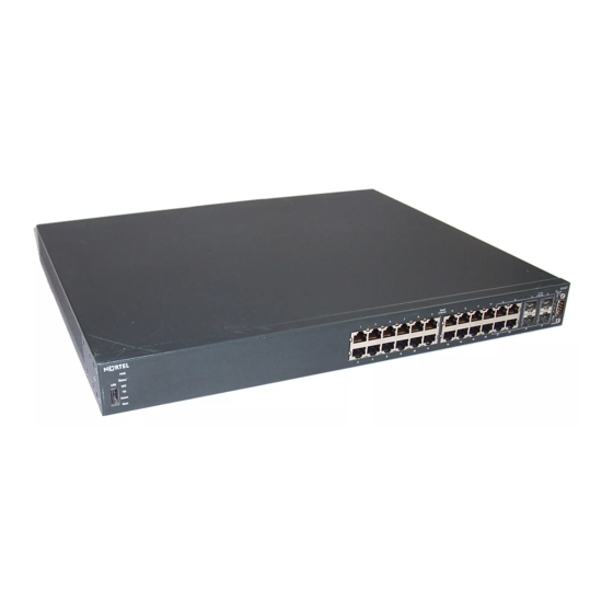
Check Light Emitting Diode (LED) on the Avaya Ethernet Routing Switch 4500 Series The figures and tables in the following sections describe the LEDs on the Avaya Ethernet Routing Switch 4500 Series switches. The tables describe LED operation for a switch that finishes the power-on self-test. - Page 38 Installing the Avaya Ethernet Routing Switch Figure 4: Avaya Ethernet Routing Switch 4548GT Figure 5: Avaya Ethernet Routing Switch 4548GT-PWR 1. USB port 4. Shared SFP Transceiver Ports (LEDs above ports) 2. Switch LEDs 5. Console Port 3. 10/100/1000 Ports (LEDs above ports)
- Page 39 Check Light Emitting Diode (LED) on the Avaya Ethernet Routing Switch 4500 Series Figure 6: Avaya Ethernet Routing Switch 4550T Figure 7: Avaya Ethernet Routing Switch 4550T-PWR 1. USB port 4. combo 10/100/1000 SFP ports (LEDs above ports) 2. Switch LEDs 5.
- Page 40 Installing the Avaya Ethernet Routing Switch Figure 9: Avaya Ethernet Routing Switch 4526T 1. USB Port 4. combo 10/100/1000/SFP ports 2. Switch LEDs 5. Console Port 3. 10/100 ports (LEDs above ports) Figure 10: Avaya Ethernet Routing Switch 4526T-PWR 1. USB Port 4.
- Page 41 Check Light Emitting Diode (LED) on the Avaya Ethernet Routing Switch 4500 Series Figure 11: Avaya Ethernet Routing Switch 4524GT Figure 12: Avaya Ethernet Routing Switch 4524GT-PWR 1. USB Port 4. Shared SFP ports: can support low speed SFPs, for example — 100FX SFP 2.
- Page 42 Installing the Avaya Ethernet Routing Switch 3. 10Gig XFP slots 6. Console Port Figure 14: Avaya Ethernet Routing Switch 4526GTX-PWR 1. USB Port 4. 10/100/1000 ports (LEDs above ports) 2. Switch LEDs 5. Shared SFP ports 3. 10Gig XFP slots 6.
- Page 43 Check Light Emitting Diode (LED) on the Avaya Ethernet Routing Switch 4500 Series Label Color and Status Description The switch failed the power-on self-test (POST) or failed to load the agent code. Green, steady The switch is connected to a redundant power supply unit (RPS) and is receiving power if necessary.
- Page 44 Installing the Avaya Ethernet Routing Switch Table 15: RJ-45 Port LED state indicators Label Color and Status Description Speed/PoE Green, Pulse Green The port is set to operate at 1000 Mb/s on gigabit PoE —Green models (ERS 4524GT-PWR, 4526GTX-PWR and 4548GT-PWR) and 100 Mb/s on the Fast Ethernet models (ERS 4526T-PWR &...
-
Page 45: Set Ip Parameters For The Avaya Ethernet Routing Switch 4500 Series
Set IP parameters for the Avaya Ethernet Routing Switch 4500 Series After an Avaya Ethernet Routing Switch 4500 Series switch starts up and initializes all software modules, it begins switching operations. To manage the switch using Telnet or SNMP, or to perform TFTP operations, you must set certain IP parameters. - Page 46 Installing the Avaya Ethernet Routing Switch 1. Connect a terminal to the console port of the switch. You can use any terminal or PC with an appropriate terminal emulator as the management station.The following table lists the parameters that you must use with any terminal emulation software used to connect to the switch.
- Page 47 Basic switch parameters have now been configured and saved. Important: Avaya Ethernet Routing Switch 4500 Series only supports the Avaya CLI, the old 'Bay Stack' menu interface is not supported on this product. When the switch is set to factory default parameters, the CLI Quickstart appears which enables you to set default IP information.
-
Page 48: Set Ip Parameters Using Ip.cfg File On A Usb Memory Device
Installing the Avaya Ethernet Routing Switch 4. After the Avaya banner appears, press CTRL + Y to display the CLI prompt. 5. To enter the Global Configuration command mode, use the enable command. 6. At the prompt, enter the configure terminal command. - Page 49 Set IP parameters for the Avaya Ethernet Routing Switch 4500 Series Table 17: IP.CFG file Parameter Description IP <xx.xx.xx.xx> Specifies the IP address for the switch. Example: 192.168.22.1 Mask <xx.xx.xx.xx> Specifies the network mask. Example: 255.255.255.0 Gateway <xx.xx.xx.xx> Specifies the default gateway. Example: 181.30.30.254...
- Page 50 If you have a console connected to the switch / stack, then while the system retrieves the ip.cfg file from the USB memory device, the Avaya banner page appears. If you use the serial console while the system is restarting or within the first few minutes after booting, then the switch will not load the IP.CFG file.
-
Page 51: Set Ip Parameters Using Bootp
IP.CFG process to load the designated software. Checking the status of the download Perform this procedure to check the status of the download three minutes after the Avaya banner page appears. Press CTRL and y keys together. -
Page 52: Setting Ip Parameters Using The Web-Based Management Interface
Installing the Avaya Ethernet Routing Switch Setting IP parameters using the Web-based Management Interface To set IP parameters using the Web-based Management Interface, perform the following procedure. Prerequisites Ensure that the switch has an IP address. 1. Connect a computer to the switch through a data port using a standard RJ-45 network cable. -
Page 53: Avaya Ethernet Routing Switch 4500 Series Stacking
The Avaya Ethernet Routing Switch 4500 Series provides fail-safe stackability. You can connect up to eight 4500 Series devices in a stack to provide uninterrupted connectivity for up to 400 ports. You can manage the stack as a single unit. - Page 54 Figure 18: Connecting cascade cables on page 56. Important: To create a stack connection, order the appropriate Avaya Ethernet Routing Switch 4500 Series cascade cables to ensure fail-safe stacking. A 1.5 foot stacking cable is included with Installation November 2010...
- Page 55 Avaya Ethernet Routing Switch 4500 series stacking the switch. For stacking three or more units (maximum eight units per stack), order the 5 ft, 10 ft, 14 ft or 16.4 ft. cables as applicable. Cascade Up connector The Cascade Up connector provides an attachment point that accepts a cascade cable connection from another unit in the stack.
- Page 56 Installing the Avaya Ethernet Routing Switch Figure 18: Connecting cascade cables 1. Base Unit 2. Cascade Cable (connected from Base Unit Cascade Down connector to Unit 2 Cascade Up connector) 3. Cascade Cable (connected from Unit 2 Cascade Down connector to Base Unit...
- Page 57 Redundant cascade stacking The Avaya Ethernet Routing Switch 4500 Series allows a stack of up to eight units into a dual- path cascade stack. If any single unit fails, or if a cable is accidently disconnected, other units in the stack remain operational.
- Page 58 Important: Automatic Unit Replacement (AUR) for both configuration and software is enabled for all Avaya Ethernet Routing Switch 4500 Series platforms and software releases. This means that the agent code image, on a replacement unit, is automatically upgraded or downgraded...
-
Page 59: Stack Configurations
Because stack parameters are associated with the base unit, the physical stack order depends on the base unit position and whether you configure the stack cascade up (stack up) or cascade down (stack down). This designation depends on the stack cabling arrangement. Avaya recommends that you use Cascade Down configuration. See Cascade down on page 59. - Page 60 Important: Because many network management software packages assume a cascade down (stack down) configuration, Avaya recommends that you use a cascade down configuration. Cascade up In a cascade up (stack up) configuration, the base unit is physically the top unit in the stack.
- Page 61 3. Cascade Down connector with cable connected 4. Cascade Cable Important: Because many network management software packages use a cascade down (stack down) configuration, Avaya recommends that you use a cascade down configuration. See Cascade down on page 59. The following guidelines apply for stack configuration: •...
- Page 62 Installing the Avaya Ethernet Routing Switch • You can perform a software upgrade on the stack from any switch using a Telnet session, the Web-based Management Interface, or any SNMP-based management software. • You can manage the stack using a Telnet session, Web-based Management Interface, or any SNMP-based management software through any stack switch port.
- Page 63 Chapter 5: Translations of safety messages Caution: When you mount this device in a rack, do not stack units directly on top of one another. You must secure each unit to the rack with appropriate mounting brackets. Mounting brackets cannot support multiple units.
- Page 64 Translations of safety messages Caution: If you are not installing a module in the slot, be sure to keep the metal cover plate in place over the slot. Removing the cover plate impedes airflow and proper cooling of the unit. Important: Achtung: Wenn Sie kein Modul im Schacht verwenden, muß...
- Page 65 Warning: Disconnecting the AC power cord is the only way to turn off AC power to this device. Always connect the AC power cord in a quickly and safely accessible location in case of an emergency. Important: Warnung: Das Gerät kann nur durch Ziehen des Netzsteckers ausgeschaltet werden. Schließen Sie das Netzkabel an einer Steckdose an, die in Notfällen schnell und sicher zugänglich ist.
- Page 66 Translations of safety messages Important: Avviso: L'unico modo per disattivare questo dispositivo consiste nello scollegare il cavo di alimentazione. Collegare sempre il cavo di alimentazione ad una presa che sia facilmente e rapidamente accessibile in caso di emergenza. Danger: Use only power cords that have a grounding path. Without a proper ground, a person who touches the switch is in danger of receiving an electrical shock.