Table of Contents
Troubleshooting

Related Manuals for Pentair AK110


Summary of Contents for Pentair AK110
- Page 1 ACU-TROL CHEMICAL CONTROLLER ® FOR POOL AND SPA MODEL AK110 INSTALLATION AND USER’S GUIDE Certi ed to NS F/ ANSI Standa rd 50 IMPORTANT SAFETY INSTRUCTIONS READ AND FOLLOW ALL INSTRUCTIONS SAVE THESE INSTRUCTIONS...
- Page 2 CUSTOMER SERVICE / TECHNICAL SUPPORT If you have questions about ordering Pentair Aquatic Systems replacement parts, and pool products, please contact: Sanford, North Carolina (8 A.M. to 4:30 P.M. ET) Customer Service and Technical Support, USA (8 A.M. to 4:30 P.M. — Eastern/Pacific Times)
-
Page 3: Table Of Contents
CONTENTS SECTION 1 INFORMATION IMPORTANT WARNING AND SAFETY INSTRUCTIONS . . . . . . . . . . . . . . . . . . . . . . . . . . . . . . . . . . . . . . . . . . . . . . . . . . . . . . . . . . . . . .5-6 CONTROLLER OVERVIEW . - Page 4 AK110 CHEMICAL CONTROLLER ILLUSTRATED PARTS LIST . . . . . . . . . . . . . . . . .
-
Page 5: Important Warning And Safety Instructions
BEFORE WORKING ON THE AK110 CHEMICAL CONTROLLER: Always disconnect power to the AK110 controller at the circuit breaker before servicing. Failure to do so could result in death or serious injury to service person, pool users or others due to electric shock. - Page 6 Securely fasten all electrical, water and chemical lines. Locate chemical feed pumps and chemical storage tanks in a safe and secure area. WARNING CHEMICAL HAZARD CONDITION DO NOT TURN CHEMICAL FEED PUMPS ON WHEN BOTH FLOW CELL VALVES ARE CLOSED. ACU-TROL AK110 Chemical Controller Installation and User's Guide ®...
-
Page 7: Controller Overview
AK110 Pool and Spa Chemical Controller Overview The AK110PS Pool and Spa Chemical Controller ("Controller") is a microprocessor based modular automation system capable of continuous local or remote monitoring and control of water chemistry for pool and spa applications . The Controller will maintain the pH and sanitizer levels of your water system automatically . -
Page 8: Section 2 Installation
Calibrate the probes, then re-calibrate as the probes acclimate to the system . Acclimation can take as little as two hours or as long as 24 hours . 14 . Program the Controller . 15. Call or visit the controller over the next few days to insure the system is balanced and in control. Fine-tune the setup if necessary . ACU-TROL AK110 Chemical Controller Installation and User's Guide ®... -
Page 9: Mounting Instructions
Controller using hardware provided . 10. Mount on a flat surface. Controller box will distort if mounted on an uneven surface. 11 . Pre-install screws with ¼ left out on bottom so that the Controller can slide into them . Install the remaining side screws and tighten . ACU-TROL ® AK110 Chemical Controller Installation and User's Guide... -
Page 10: Electrical Specifications
If the Controller is connected to 220 VAC the voltage selection switch must be changed to 220 VAC before connecting power to the unit or damage will occur. Note: It is not possible to power the AK110 Chemical Controller with 110 VAC, and control 220 VAC loads or vise versa . -
Page 11: Electrical Loads
Circuits, with common white and no ground. The wiring on each board may be different depending on the model that you purchase . Look on the board, check with your distributor or call Pentair Customer Support at 800-831-7133 with any questions . WARNING Do not change relay modules when power is applied. -
Page 12: Relay Board
RELAY BOARD Relay 1: Configured for pH control . Relay 2: Configured for ORP control . Relay 3: User configured ACU-TROL AK110 Chemical Controller Installation and User's Guide ®... -
Page 13: Chemical Feed Pump Location
DO NOT attempt to power the heater with the Controller controller . A heater unit must always be independently powered, either through a separate cord, or through an external relay like the Acu-Trol HAR1 relay module. (Part# 735000060) Always use the over-temp device on the heater to prevent overheating . ACU-TROL ® AK110 Chemical Controller Installation and User's Guide... -
Page 14: Plumbing Installation
Prepare and install the chemical injector fittings. Install the chemical storage containers . Install the sensors . Turn ON the main circulation pump . 10 . Check for leaks and verify the flow sensor indicates flow . ACU-TROL AK110 Chemical Controller Installation and User's Guide ®... - Page 15 WARNING Do not inject acid directly in to the AK1200 flow cell. Injecting acid in this way may damage the existing pool equipment. Pool Pump Water Sample Test Preferred Plumbing Routes ACU-TROL ® AK110 Chemical Controller Installation and User's Guide...
-
Page 16: Section 3 Hardware
. To determine the load requirements, please consult the instruction manual or the device manufacturer . Any combination of the seven models of relay modules can be installed in the three available slots on a relay board, as long as the combination does not exceed the combined maximum current for the relayboard. The combined maximum current for any individual relay board is 5 amps. ACU-TROL AK110 Chemical Controller Installation and User's Guide ®... - Page 17 24 VAC . They are always powered, and the wiring will dictate whether the power flows in the on or off position . The relay ratings are 1A and 250 VAC . The neutral is common for both NO and NC . ACU-TROL ® AK110 Chemical Controller Installation and User's Guide...
-
Page 18: Section 4 Ak1200 Flow Cell
Remove flow cell from shipping carton and make sure all parts are included with AK1200 flow cell . • 1 – AK1200 Lid • 1 – AK1200 Jar with O-Ring • 1 – Flow switch magnet • 3 - ¼” Valves. • 1 - Sample barb fitting • 4 - ¼” NPT by ½” flex fittings. • 1 - Filter assembly with O-Ring • 2 - ¼” plugs. • 1 - Flow switch with O-Ring, 2’ • 1 - ¼” Close Nipple and 10’ wire lengths available. • 1 - Threaded Seal Tape • 2 - Mounting screws Note that ½” flexible tubing is not included and is supplied by the installer or may be ordered from Acu-Trol. ACU-TROL AK110 Chemical Controller Installation and User's Guide ®... -
Page 19: Flow Cell Assembly
Inlet should be installed after filter and before heater . Exit should be installed after heater and as far away from any equipment as possible. Drill and tap at above locations with 7/16” drill and 1/4” NPT tap . Choose a location on a fitting where the pipe enters so you are drilling through both the pipe and fitting to get maximum depth of thread. Install ¼” NPT by ½” flex fittings then route inlet and exit lines. ACU-TROL AK110 Chemical Controller Installation and User's Guide ®... - Page 20 Use with any other brand Controller VOIDS WARRANTY. WARNING: Make sure all pumps are OFF before drilling into pipes. Never turn chemical feed pumps ON when both flow cell valves are closed. ACU-TROL AK110 Chemical Controller Installation and User's Guide ®...
-
Page 21: Section 5 Sensors
Controller enclosure . DO NOT CUT THE SENSOR WIRES. Do not stuff excess wire inside the controller as this may cause excess strain on sensor and relay connections. ACU-TROL ® AK110 Chemical Controller Installation and User's Guide... -
Page 22: Calculated Ppm
Calculated PPM If you have an ORP sensor module you can choose to operate the AK110 in Calculated PPM (Parts Per Million) mode . When in Calculated PPM mode, the Controller uses a special formula to convert the ORP reading from the sensor in to PPM units. To activate the Calculated PPM mode, select "PPM, Mix Time" or "PPM, Cycle Time" in the wizard section. -
Page 23: Sensor Care
"automatically" off . Press the Right button 1 time to R1 (ph) OFF and press ENTER to "manually" turn on the load, verify that the correct load turns on and press enter to turn it off . Press the down arrow to select the next relay and repeat for the other two relays. ACU-TROL ® AK110 Chemical Controller Installation and User's Guide... -
Page 24: Section 6 Operations
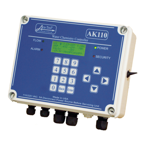
Main Status, cursor at pH value that displays at startup . pH > 7.67-OFF 7.50s 2 . Menu List: for editing and setup of parameters . ORP 490 -OFF 700s _____ 69.0f SW1OFFSW2OFF ACU-TROL AK110 Chemical Controller Installation and User's Guide ®... -
Page 25: Selecting Items In The Windows
Press the ENTER button to save the chang NOTE Changes must be saved by pressing the final ENTER. If ENTER is not pressed as the last step the changes with not be saved. ACU-TROL ® AK110 Chemical Controller Installation and User's Guide... -
Page 26: Start Up
. To change set points you will need to go to programming and change them there . Pressing the Up Arrow key when the curser is at the top of the readings screen will move you back to the opening screen . ACU-TROL AK110 Chemical Controller Installation and User's Guide ®... -
Page 27: Display Screen
ENTER . Enter the value obtained from the test kit in to the value entry screen . Press ENTER again to save your changes . ACU-TROL ® AK110 Chemical Controller Installation and User's Guide... -
Page 28: Calibrating Orp
May need to decrease chemical feed times & calibrate to High check hand check At hand check Lower the set point Below hand Calibrate to hand check measurement: 10mV per each check PPM High ACU-TROL AK110 Chemical Controller Installation and User's Guide ®... -
Page 29: Calibrating Calculated Ppm
7.67>OFF 7.50s ORP 490 -OFF 700s relay is toggled to OFF the relay immediately goes back to _____ automatic control and in some cases may immediately turn 69.0f SW1OFFSW2OFF back ON . ACU-TROL ® AK110 Chemical Controller Installation and User's Guide... -
Page 30: Relay Time Display
Flow Switch 2 Setup Flow Switch #2 SW2 K => 8.5 pul/g Total = 256 Clear NOTE: If k = 0 than g/m = and Total = will not be displayed on the screen. ACU-TROL AK110 Chemical Controller Installation and User's Guide ®... -
Page 31: Configuration Menu
Internet Modems . See pages 106 for Programming Screen Navigation Email . • Security Setup: Sets up passwords, clears passwords, and resets all settings to factory defaults. See pages 126 for Security Setup Screen Naviagtions . • Wizards: Select pre-written programs for common Controller applications. See pages 110 for Wizards Setup Screen Navigation . • Serial #: View the serial number here. The serial number is required when requesting support. ACU-TROL ® AK110 Chemical Controller Installation and User's Guide... -
Page 32: Name
English is selected the date format is mm/dd/yy . • Sanitizer: Select between “Cl” (chlorine) and “Br” (bromine). • On Delay: Pressing Enter on this line increments (by 15) the number of seconds the relays will be off on power up . • Backlight Time: Select the amount of time the Controller screen backlight will be on each time the control panel is activated . • Temp Display: Displays water temperature in farnihiet degrees. To turn temperature sensor off, toggle on/off and select enter . • Reset to Default: Returns Controller to original factory default settings. ACU-TROL AK110 Chemical Controller Installation and User's Guide ®... -
Page 33: Programming
. For best results, the proportional feed percentage should be kept between 0 and 5 percent . ACU-TROL ® AK110 Chemical Controller Installation and User's Guide... - Page 34 OPR Indicating Timer Screen, Clear Overfeed Condition Overfeed 7.67>OFF 7.50s ORP, Mix TMR00:00:00 ORP 490 -OVR 700s >TD01:30:00 _____ CNT: 0 S 00:00:00 69.0f SW1OFFSW2OFF STS:OVR TOT 0:00 ACU-TROL AK110 Chemical Controller Installation and User's Guide ®...
-
Page 35: Service
. When downloading the data with a PC the following information will also be displayed: Title = MPBPF123: Modem, PC RS232, Front Button pressed, Password entered, Flow S1 on, and relays 1-3 status . ACU-TROL ® AK110 Chemical Controller Installation and User's Guide... -
Page 36: Communications
. See AK110 Programming Screen Navigation on page 88 for details on alarms . Make sure to enter the "comma" to allow enough delay time for the modem on the other end to pick up . Each comma is worth 4 seconds of time . -
Page 37: Email Setup
The numbers 9000-9010 are reserved for technical support purposes and may not be used . 3 . A master password is required for should a wireless modem be installed in the AK110 . See page 126 for the AK110 Security Set-up Screen Navigation for more detailed security set-up process . -
Page 38: Wizards
11 . ORP/PPM, Cycle Time - optional method see program . Control options for Pager/Email 1-4 Pager 1-4/Email 1-4 Not Used See page 110 for the AK110 Wizards Setup Screen Navigation ACU-TROL AK110 Chemical Controller Installation and User's Guide ®... -
Page 39: Section 7 Troubleshooting
. The Controller will automatically detect the real time clock when it is installed . The real time clock is battery pow- ered, with a minimum of 5 years battery life . ACU-TROL ® AK110 Chemical Controller Installation and User's Guide... -
Page 40: Orp Troubleshooting
Call Acu-Trol Technical Support at 800-273-4667 with the sensor readings if your results do not match the following readings: ORP 90350-28A pH = 7.65-7.75 ORP = 485-500 Temp = 68.0-71.0 PPM 90350-35A pH = 7.65-7.75 Color = TBD Temp = 68.0-71.0 ACU-TROL AK110 Chemical Controller Installation and User's Guide ®... -
Page 41: Akcolor Ppm Troubleshooting
1 . Confirm that there is flow in the Flow Cell 2 . Clean the pH sensor using the Acu-Trol pH sensor or cleaning procedure listed in this manual . pH readings inaccurate 1 . Recalibrate the pH reading ACU-TROL ® AK110 Chemical Controller Installation and User's Guide... -
Page 42: Section 8
00:06:00 00:00:00 00:06:00 00:05:54 00:00:06 00:06:00 00:00:06 00:05:54 00:06:00 00:03:00 00:03:00 00:06:00 00:05:06 00:00:54 00:06:00 00:06:00 00:00:00 00:06:00 Table 3 . ORP Control with the Cycle Time control type . Cycle time = 6 minutes ACU-TROL AK110 Chemical Controller Installation and User's Guide ®... -
Page 43: Section 9 Wiring Diagrams
Acu-Trol Pigtails White Wire to NOW or Gangbox Sanitizer Feed Pump Normally Closed (NC) Relay (Optional) Acid Feed Pump Green Wire to GND Black Wire to NCB White Wire to NCW ACU-TROL ® AK110 Chemical Controller Installation and User's Guide... -
Page 44: Sensor Wiring Diagrams
AK110PS Chemical Controller Bottom View Control Board Sensor Card Green Terminal Bar Green Terminal Bar Sensor Sensor Flow Switch pH Sensor Wires = Green to pH - = Copper to pH + ORP Sensor Wires = Green to ORP - = Copper to ORP + Flow Switch Wires = Red to GND = Black to Switch 1 ACU-TROL AK110 Chemical Controller Installation and User's Guide ®... -
Page 45: Section 10 Menus
PLEASE CALL 800-831-7133 FOR TECHNICAL ASSISTANCE. NOTE: The keypads on the mounted AK110 Chemical Controller do not have the letter of the alphabet or numbers printed on the keypad. The some models curser keys do not have "Delete", "To Right", "Cancel"... -
Page 46: Main Status Screen Navigations
10.1... -
Page 50: Relay And Alarm Timer Screen Navigation
10.2... -
Page 52: Configuration Menu Screen Navigation
10.3... -
Page 54: Controller Name Screen Navigation
10.4... -
Page 56: System Setup Screen Navigation
10.5... -
Page 58: Programming Screen Navigation , Ph Mix Time
10.6... -
Page 60: Programming Screen Navigation, Ph Cycle Time
10.7... -
Page 62: Programming Screen Navigation, Orp Mix Time
10.8... -
Page 66: Programming Screen Navigation, Orp Cycle Time
10.9... -
Page 70: Programming Screen Navigation, Orp Cal Hypo
10.10... -
Page 74: Programming Screen Navigation, Ppm Cycle Time
10.11... -
Page 78: Programming Screen Navigation, Pmm Mix Time
10.12... -
Page 82: Programming Screen Navigation, Probe Clean
10.13... -
Page 84: Programming Screen Navigation, Heater
10.14... - Page 86 10.15...
-
Page 90: Programming Screen Navigation, Aux . Make-Up (Auto-Fill)
10.16... -
Page 92: Programming Screen Navigation, Daily Event
10.17... - Page 94 10.18...
-
Page 96: Programming Screen Navigation, Alarm Out
10.19... -
Page 100: Programming Screen Navigation
10.20... -
Page 104: Programming Screen Navigation, Email
10.22... -
Page 108: Wizards Setup Screen Navigation
10.23... -
Page 112: Data Screen Navigation
10.24... -
Page 114: Communications Screen Dial-Up
10.25... -
Page 118: Communications Screen Internet Modems
10.26... -
Page 124: Security Setup Screen Navigation
10.27... -
Page 126: Akcolor Screen Navigation
10.28... -
Page 128: Service Screen Navigation
-Confirm Changes Enter Clear Calibrations -Clear RLY Timers Clear Data > Clear RLY Timers NO:7 9:YES Press the [9] key reset all relay timers or press the [7] key to cancel. AK110 Service Screen Navigation, Rev 3 21 Aug 2008... - Page 129 ORP and PPM Chart PPM v. ORP at pH 7.4-7.6 690 695 700 705 710 715 720 725 730 735 740 745 750 755 760 765 770 775 How to use this chart: The values on the left side of the chart are free-chlorine PPM. The values on the bottom are the approximate equivalent ORP Values.
-
Page 130: Ak110 Chemical Controller Illustrated Parts List
AK110 Pool and Spa Chemical Controller Illustrated Parts 17 (2) 16 (2) 11 (4) ACU-TROL AK110 Chemical Controller Installation and User's Guide ®... - Page 131 AK110 Pool and Spa Chemical Controller Illustrated Parts List DWG . # PART # DESCRIPTION 715000150 Enclosure, Lid, w/overlay and hardware 724000260 PCB, Control Board, w/display and hardware 724000010 PCB, Sensor, pH/orp/temp w/hardware 724000020 PCB, Sensor, pH/temp/AKColor, w/hardware 724000280 PCB, Module, Real Time Clock, w/hardware...
- Page 132 Pentair Water Pool and Spa, Inc. Those names and brands may be the trademarks or registered trademarks of those third parties.