Table of Contents
Advertisement
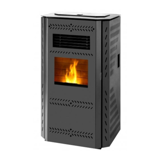
IMPERIAL PELLET STOVE
Manufactured By:
INSTALLATION & OPERATION
England's Stove Works, Inc.
MANUAL
PO Box 206
25-IP/55-SHPIP/55-TRPIP
Monroe, VA 24574
10/7/2013
25-IPS/55-SHPIPS/55-TRPIPS
CAUTION
PLEASE READ THIS ENTIRE MANUAL BEFORE INSTALLATION AND USE OF THIS PELLET FUEL-BURNING
APPLIANCE. KEEP CHILDREN, FURNITURE, AND ALL COMBUSTIBLES AWAY FROM ANY HEATING APPLIANCE.
SAFETY NOTICE
FAILURE TO FOLLOW THESE INSTRUCTIONS CAN RESULT IN PROPERTY DAMAGE, BODILY INJURY OR EVEN
DEATH. FOR YOUR SAFETY AND PROTECTION, FOLLOW THE INSTALLATION INSTRUCTIONS OUTLINED IN
THIS MANUAL. CONTACT YOUR LOCAL BUILDING OR FIRE OFFICIALS ABOUT RESTRICTIONS AND
INSTALLATION INSPECTION REQUIREMENTS (INCLUDING PERMITS) IN YOUR AREA.
SAVE THESE INSTRUCTIONS
Advertisement
Table of Contents

Related Manuals for England's Stove Works 25-IP


Summary of Contents for England's Stove Works 25-IP
- Page 1 IMPERIAL PELLET STOVE Manufactured By: INSTALLATION & OPERATION England’s Stove Works, Inc. MANUAL PO Box 206 25-IP/55-SHPIP/55-TRPIP Monroe, VA 24574 10/7/2013 25-IPS/55-SHPIPS/55-TRPIPS CAUTION PLEASE READ THIS ENTIRE MANUAL BEFORE INSTALLATION AND USE OF THIS PELLET FUEL-BURNING APPLIANCE. KEEP CHILDREN, FURNITURE, AND ALL COMBUSTIBLES AWAY FROM ANY HEATING APPLIANCE.
- Page 2 IMPORTANT: IF YOU HAVE A PROBLEM WITH THIS UNIT, DO NOT RETURN IT TO THE DEALER. CONTACT TECHNICAL SUPPORT @ 1-800-245-6489 Mobile Home Use: This freestanding pellet unit is approved for mobile home or doublewide installation with the outside combustion air hook-up. See the “Installation” section of this manual for details pertaining to mobile home installations.
-
Page 3: Table Of Contents
lid. Have this information on hand if the phone the factory or your dealer regarding this product. TABLE OF CONTENTS Yearly Introduction Important Notes....29 Introduction ........4 Exhaust Blower ....30 Specifications Convection Blower ..... 30 ... -
Page 4: Introduction
“on-site” repairs or maintenance that we may arrange. This manual encompasses all versions of the 25-IP, including the 55-SHPIP, 55-SHPIPL and 55-TRPIP. This also applies to the straight version of this unit with model numbers 25-IPS, 55-SHPIPS and 55-TRPIPS. However, for simplicity of description, the stove will be referred to by the generic 25-IP designation. -
Page 5: Specifications
SPECIFICATIONS Heating Specifications Heat Output Range** ..............14,108 to 35,023BTU/hr Approximate Pellet Burn Rate** ............0.945 to 2.346 kg/hr Maximum Burn Time** ..................38 hours Approximate Square Footage Heated*** ..........up to 2,200 sq. ft. Hopper Capacity.................... -
Page 6: Installation
INSTALLATION Installation Overview When choosing a location for your new stove, there are a multitude of factors that should be taken into account before beginning the installation. 1. Traffic Patterns – To help prevent accidents, the stove should be placed in a location where it is out of the way of normal travel through the home. -
Page 7: Clearances To Combustibles
INSTALLATION Clearances to Combustibles Unit to Side Unit to Rear Unit to Corner Unit Top to Min. Ceiling Wall (A) Wall (B) Ceiling Height 6 in. 6 in. 3 in. 9 in. 60 in. 152.4 mm 152.4 mm 76.2 mm 228.6 mm 1524 mm Alcove installation not recommended for this unit... -
Page 8: Venting Introduction
INSTALLATION Venting Introduction This pellet stove operates on a negative draft system, which pulls combustion air through the burn pot and pushes the exhaust air through the vent pipe and out of the building. This unit must be installed in accordance with the following detailed descriptions of venting techniques; not installing the stove in accordance with the details listed here can result in poor stove performance, property damage, bodily injury or death. -
Page 9: Additional Venting Information
INSTALLATION Additional Venting Information Do not mix and match components from different pipe manufacturers when assembling your venting system (i.e. Do NOT use venting pipe from one manufacturer and a thimble from another). We require a minimum vertical rise of 36 in. (3 ft.) of pipe to create natural draft in the system, which helps evacuate smoke from the stove in the event of a power failure or combustion blower failure. -
Page 10: Approved Venting Methods Through The Wall
For high altitude installations INSTALLATION (above 4,000 ft.), the vent pipe should be increased from 3-inch Approved Venting Method 1: Through the Wall (3”) to four-inch (4”). Generally the simplest installation method, venting through the wall using our AC-3000 kit, AC-33000 if Canada (or similar venting system) is also the preferred venting method. -
Page 11: Through The Ceiling
For high altitude installations INSTALLATION (above 4,000 ft.), the vent pipe should be increased from 3-inch Approved Venting Method 2: Through the Ceiling (3”) to four-inch (4”). Venting through the ceiling/roof may be the only feasible venting option in some cases and is a factory recommended installation. -
Page 12: Existing Chimney
For high altitude installations INSTALLATION (above 4,000 ft.), the vent pipe should be increased from 3-inch (3”) to four-inch (4”). Approved Venting Method 3: Existing Chimney System Using an existing masonry or factory built chimney for venting is the only other acceptable method for venting this pellet unit. -
Page 13: Mobile Home Installation
For high altitude installations INSTALLATION (above 4,000 ft.), the vent pipe should be increased from 3-inch Mobile Home Installation (3”) to four-inch (4”). The England’s Stove Works, Inc. outside air kit MUST be used for installation of this unit in a mobile home. -
Page 14: Vent Termination Clearances
VENT TERMINATION CLEARANCES A) MIN. 4-FT CLEARANCE BELOW OR BESIDE ANY DOOR OR WINDOW THAT OPENS. B) MIN. 1-FT CLEARANCE ABOVE ANY DOOR OR WINDOW THAT OPENS. C) MIN. 2-FT CLEARANCE FROM ANY ADJACENT BUILDING. D) MIN. 7-FT CLEARANCE FROM ANY GRADE WHEN ADJACENT TO PUBLIC WALKWAYS. E) MIN. -
Page 15: Outside Air Hookup
OUTSIDE AIR HOOK-UP The use of outside combustion air is mandatory on this pellet stove. The outside air connection pipe protrudes from the lower rear center of the stove; use the included outside air kit to attach your stove to outside combustion air. Instructions and all the parts needed to make the outside air connection to your pellet stove are included with the outside air kit. -
Page 16: Floor Protection
FLOOR PROTECTION This pellet stove requires a non-combustible floor protector if the stove is to be installed on a combustible floor. If the floor the stove is to be installed on is already non-combustible (i.e. a concrete floor in a basement) and has an R value equal to or higher than .2, no floor protection is needed (although a decorative floor protector can still be used for aesthetic reasons). -
Page 17: Daily Operation
DAILY OPERATION Getting Started Check to see that the hopper is clean and free from foreign materials. Be sure to connect this unit to a working outlet; we recommend using a surge protector to help protect the electronic components from damage. - Page 18 The fuel feed rate and combustion air during start-up is determined by the control board, so the stove may be started on any heat range. After approximately fifteen minutes, the fire should be burning brightly and the “S U” should disappear from the control board.
-
Page 19: Control Board Settings
CONTROL BOARD SETTINGS The control board on this stove allows the user to adjust the heat output and convection blower speed, turn the unit on and off, and test components for function (more on diagnostic mode later). The lower buttons on the control board (Low Fuel Feed, Low Burn Air, and Air on Temp) are not meant to be adjusted during normal operation of the unit. -
Page 20: Error Codes
ERROR CODES Error codes, or “E-Codes,” are alphanumeric codes that will appear in the Heat Range and Blower Speed windows of the Control Board if the unit experiences an abnormal condition. Error codes are the control board’s way of telling the user that something isn’t operating correctly within the stove, and that the unit should be carefully inspected before reigniting. -
Page 21: Power Failure
POWER FAILURE If the power to the unit is interrupted for approximately three minutes or less, the unit will resume operation when power is restored according to the following table: Unit’s State Before Power Loss State When Power Returns Start-Up Start-Up Start-Up Shut-Down... -
Page 22: Thermostat Installation
THERMOSTAT OPERATION Thermostat Installation 1. Unplug the unit and remove the back panel of the stove, using a ” wrench. 2. Locate the thermostat connect block, labeled J18, on the rear of the control board, near the bottom (See image below and pg. 40 of this manual for a control board diagram). It will have a small wire “jumper”... -
Page 23: Optional Accessories
Wall Thermostat (PU-DTSTAT) Installing this wall thermostat allows the 25-IP to operate on the same principle as a furnace: The stove will shut-down and relight as the call for heat comes and goes (in “On/Off mode,” see previous page). This will maintain the house at a more constant temperature, while conserving pellets. -
Page 24: Important Notes
*Failure to properly clean your stove can cause poor performance and possibly a burn back!* DAILY MAINTENANCE Disposal of Ashes – Ashes should be placed in a metal container with a tight fitting lid. The closed container of ashes should be placed on a noncombustible floor or on the ground, well away from all combustible materials, pending final disposal. -
Page 25: Cleaning The Burn Pot
Because of the open design of the firebox, the majority of the ash will be on either side of the cradle. Open the front panel, then the main door of the stove and use an old paint brush or putty knife to move ash from around the burn pot into the open areas besi de the cradle. -
Page 26: Bi-Weekly
Insert the burn pot back into the cradle using the reverse of the procedure detailed above. BI-WEEKLY MAINTENANCE Baffle Removal As with any maintenance concerning this unit, be sure the unit is “OFF,” has completed the Shut-Down cycle, and is completely cool BEFORE beginning. Be aware that metal parts in the firebox can remain HOT long after the fire has gone out and EVEN after the Shut-Down cycle is complete. -
Page 27: Exhaust Chamber
caution when handling potentially hot stove parts, even if you think they should be cold. Monthly maintenance should include the steps listed in this section AS WELL AS the steps listed in the “Daily Maintenance” and “Bi-weekly Maintenance” section. ... -
Page 28: Venting Pipe
A specially designed ash vacuum and pellet stove cleaning kit is available from the England’s Stove Works website; please see: http://www.englanderstoves.com/store/. Once all ash has been removed from the exhaust chamber, reinstall the cleanout port covers, using the screws previously removed. ... -
Page 29: Important Notes
YEARLY MAINTENANCE Important Notes As with any maintenance concerning this unit, be sure the unit is “OFF,” has completed the Shut-Down cycle, and is completely cool BEFORE beginning. Be aware that metal parts in the firebox can remain HOT long after the fire has gone out and EVEN after the Shut-Down cycle is complete. -
Page 30: Exhaust Blower
YEARLY MAINTENANCE Exhaust Blower Cleaning Although the exhaust blower and blower housing were designed to minimize ash build-up, some fly- ash will still accumulate there throughout the burning season. The amount and type of ash will depend on the type of pellets and venting system, but generally this accumulation will be mild. If, when cleaning the exhaust blower, a large accumulation of fly-ash is found, cleaning the exhaust blower and housing should be performed monthly or bimonthly to prevent this excess buildup. -
Page 31: Cradle Removal
YEARLY MAINTENANCE Cradle Removal and Cleaning The cradle needs to be removed yearly, to be cleaned and to replace the cradle gasket. To remove the cradle: First, remove the back panel from the stove (using a ” socket). Looking into the stove from the front, loosen the two bolts in the front that hold the cradle, then remove the igniter (see page 36). -
Page 32: Troubleshooting Guide
Trouble-Shooting Guide WARNING: To avoid ELECTRICAL SHOCK always disconnect the unit from the power source BEFORE attempting any repair. If this guide does not correct the problem, call your local dealer or Technical Support at 1-800-245-6489. Problem Cause Solution Auger not turning 1. - Page 33 Unit Shuts Down in 15-20 1. Loose thermal sensor. 1. Check both sides of thermal minutes with an "E-2" code sensor connection (exhaust blower on control board. and control board). 2. Control board settings. 2. Start stove on minimum Heat Range 5 to ensure a good fire is started.
-
Page 34: Replacing Components
REPLACING COMPONENTS Auger Motor 1. Before beginning any component replacement, be certain the unit is unplugged and thoroughly cooled down. Also, make sure the hopper is empty before attempting to remove or replace the auger motor assembly. 2. Remove the back panel of the unit, using a ”... -
Page 35: Convection Blower
REPLACING COMPONENTS Convection Blower 1. Before beginning any component replacement, be certain the unit is unplugged and thoroughly cooled down. 2. Remove the rear panel (using a ” wrench) and locate the convection blower. 3. Detach the convection blower from the wiring harness before going any further. 4. -
Page 36: Vacuum Switch
REPLACING COMPONENTS Vacuum Switch 1. Before beginning any component replacement, be certain the unit is unplugged and thoroughly cooled down. 2. Remove the right side panel (see p. 43 for panel instructions). 3. Locate the vacuum switch as shown in the diagram below. 4. -
Page 37: Gaskets
REPLACING COMPONENTS IMPROPER GASKET MAINTENANCE, INCLUDING FAILURE TO REPLACE GASKETS, CAN CAUSE AIR LEAKS RESULTING IN SMOKE-BACKS. Gaskets 1. Door o This unit comes with a ” rope gasket in the channel around the door opening that should be replaced at least once every year. To replace the door gasket (Part # AC- DGKNC), the old gasket must first be removed entirely —... -
Page 38: Glass
REPLACING COMPONENTS Glass This unit has one ceramic glass panel (Part # AC-G40) in the inner door; self adhesive window gasket is included with replacement windows purchased directly from England’s Stove Works. Never replace ceramic glass with tempered or any other type of glass and never operate this unit with cracked or broken glass. -
Page 39: Control Board
REPLACING COMPONENTS Control Board The Control Board (Part # PU-CBIP) is a digital read-out board. This board offers a wide variety of settings to operate the unit. The right side panel can be opened to remove the control board. The control board can be removed from the unit by loosening the two outside screws and pulling the board down below the mounting bracket. -
Page 40: Wiring Diagram
WIRING DIAGRAM PU-CBIP Control Board Diagram (Wiring) Caution – Shock Hazard Press the “Off” button and let the appliance completely cool BEFORE unplugging the appliance and beginning any maintenance or component replacement. Risk of shock if appliance is not unplugged before service. IMPORTANT! READ AND FOLLOW ALL INSTALLATION AND MAINTENANCE INSTRUCTIONS, INCLUDING CLEANING THE UNIT AS SPECIFIED, AND REPLACING GASKETS ANNUALLY, AND PARTS AS NEEDED. -
Page 41: Hopper Lid Latches
Adjusting your Hopper Lid Latches The seals around the top of the pellet hopper are important to safe and efficient operation of the unit. The latch installed on these units is designed to pull the hopper lid tight against this seal. Over the course of operation as these seals “wear in”... -
Page 42: Door Latch
DOOR LATCH The door latch uses a removable handle. This handle can be found in the owner’s manual packet. The handle should be stored inside the front panel in the very bottom shelf. The latch can be adjusted by loosening the screws and moving the plate forward/backward as needed. If the hook should need to be replaced, use a ”... -
Page 43: Fiberboard
FIBERBOARD To remove the fiberboard: Remove the air wash bar, located on top of the cradle. Remove the burn pot. Using a ” socket, remove the screw and washer that hold the fiberboard in place. Remove the board by pulling one side out first. ... -
Page 44: Illustrated Parts Detail Exploded Parts Diagram
ILLUSTRATED PARTS DIAGRAM Auger Motor Assembly Door Assembly IMPORTANT! READ AND FOLLOW ALL INSTALLATION AND MAINTENANCE INSTRUCTIONS, INCLUDING CLEANING THE UNIT AS SPECIFIED, AND REPLACING GASKETS ANNUALLY, AND PARTS AS NEEDED. ENGLAND’S STOVE WORKS IS NOT RESPONSIBLE FOR ANY DAMAGE OR INJURY INCURRED DUE TO NEGLECT, OR DUE TO UNSAFE INSTALLATION OR USAGE OF THIS PRODUCT. -
Page 45: Parts List
REPLACEMENT PARTS LIST Part No Description From Diagram PU-4C447 250 CFM Room Air Blower CU-047042 2.4 RPM Auger motor CW Rotation PU-076002B Combustion Exhaust Blower(Neg) Door Gasket 5/8” round AC-DGKNC AC-GGK Ash Pan Gasket AC-G40 Door Glass 10.675" x 14.438" AC-GGK Window Glass Gasket AC-HLSB... -
Page 46: Ash Pan Latches
PU-AWBIP Air Wash Bar AC-GSIP Glass Support AC-DLHIP Door Latch Handle AC-VMBIP Vacuum Switch Mounting Bracket Not shown AC-CMPIP Control Board Mounting Plate AC-CHSEP Cartridge Heater Sleeve Not shown PU-DVDIP Not shown MU-25IP Manual Not shown AC-IPG Grill PU-IPWH Wiring Harness Not shown ASH PAN LATCHES The ash pan latches can be adjusted in the same manner as the hopper lid latch (see p. -
Page 47: Serial Tag Sample
You may write your unit’s Manufacture Date and Serial Number in the blank spaces on this sample tag, for future reference. This sample tag also shows the safety info. such as UL/ULC testing standard, etc. for your local officials, or anyone else who may need reference information. IMPORTANT! READ AND FOLLOW ALL INSTALLATION AND MAINTENANCE INSTRUCTIONS, INCLUDING CLEANING THE UNIT AS SPECIFIED, AND REPLACING GASKETS ANNUALLY, AND PARTS AS NEEDED. -
Page 48: Warranty Details
LIMITED FIVE (5) YEAR WARRANTY From the date of purchase to the original owner. The manufacturer extends the following warranties: Five Year Period: 1. Carbon steel and welded seams in the firebox are covered for five (5) years against splitting. 2. - Page 49 Procedure Purchaser must give notice of claim of defect within the warranty period and pay transportation to and from a service center designated by the manufacturer. The dealer from which the unit was purchased or the factory, at our option, will perform the warranty service.
-
Page 50: Important Notice
Important Notice This registration information MUST be on file for this warranty to be valid. Please mail this information within thirty (30) days from the original date of purchase. Use any of these three easy ways to send your warranty information in! Mailing Address England’s Stove Works, Inc. -
Page 51: Warranty Reg. Form
WARRANTY REGISTRATION for England’s Stove Works® Purchaser Information I. Purchased By (Name) _________________________________________ II. Address ____________________________________________________ III. City _______________________State________Zip Code ____________ IV. Telephone Number ___________________________________________ V. Email Address _______________________________________________ Dealer Information VI. Purchased From _____________________________________________ VII. Address ___________________________________________________ VIII. City_______________________ State________ Zip Code __________ Unit Information IX.