Table of Contents
Advertisement
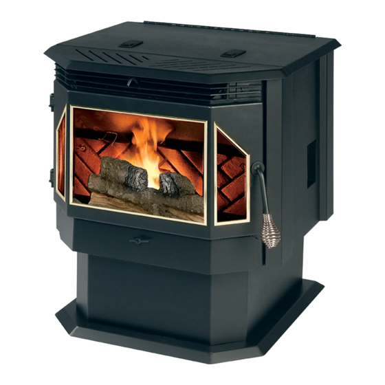
EVOLUTION PELLET STOVE
INSTALLATION & OPERATION MANUAL
Freestanding
Fireplace Insert
25-EP 55-SHPEP 55-TRPEP
25-EPI 55-SHPEPI 55-TRPEPI
CAUTION
Please read this entire manual before installation and use of this pellet fuel-
burning appliance. Keep children, furniture, fixtures and all combustibles away
from any heating appliance.
SAFETY NOTICE
Failure to follow these instructions can result in property damage, bodily injury
or even death. For your safety and protection, follow the installation
instructions outlined in this manual. Contact your local building or fire officials
about restrictions and installation inspection requirements (including permits) in
your area.
SAVE THESE INSTRUCTIONS
Rev. 1/2010
Advertisement
Table of Contents

Related Manuals for England's Stove Works 25-EP


Summary of Contents for England's Stove Works 25-EP
- Page 1 EVOLUTION PELLET STOVE INSTALLATION & OPERATION MANUAL Freestanding Fireplace Insert 25-EP 55-SHPEP 55-TRPEP 25-EPI 55-SHPEPI 55-TRPEPI CAUTION Please read this entire manual before installation and use of this pellet fuel- burning appliance. Keep children, furniture, fixtures and all combustibles away from any heating appliance.
- Page 2 IMPORTANT: IF YOU HAVE A PROBLEM WITH THIS UNIT, DO NOT RETURN IT TO THE DEALER. CONTACT TECHNICAL SUPPORT @ 1-800-245-6489 Mobile Home Use: The freestanding pellet unit is approved for mobile home or doublewide installation with the outside combustion air hook- up.
-
Page 3: Table Of Contents
TABLE OF CONTENTS Introduction Maintenance (cont’d.) Introduction ........4 Monthly o Important Notes ....37 Specifications o Exhaust Chamber ....38 Heating Specifications ....5 o Venting Pipe....39 Dimensions ........5 Yearly EPA Compliance ......5 o Important Notes ....40 o Exhaust Blower ....41 Installation (Freestanding) o Convection Blower ..43... -
Page 4: Introduction
This manual encompasses all versions of the freestanding model 25-EP, including the 55-SHPEP, 55-SHPEPL and 55-TRPEP. It also encompasses the fireplace insert models 25-EPI, 55-SHPEPI and 55-TRPEPI. However, for simplicity of description, the stove will be referred to by the generic “25-EP” designation, unless otherwise specified. Page | 4... -
Page 5: Specifications
SPECIFICATIONS Heating Specifications Heat Output Range** ..........10,700 BTU/hr – 25,100 BTU/hr Approximate Pellet Burn Rate** ..........1.6 lb/hr – 3.9 lb/hr Maximum Burn Time** ................40 hours Approximate Square Footage Heated*** ........800 - 2000 sq. ft. ... - Page 6 SPECIFICATIONS FIREPLACE INSERT DIMENSIONS Unit Height (In Fireplace) o 20.00” [508mm] Unit Depth (In Fireplace) o 9-7/16” [239.7mm] Unit Width (In Fireplace) o 21-3/16” [538.2mm] Bottom to Flue Collar o 7-1/4” [184.2mm] Left Side to Flue Collar o 5-1/2”...
-
Page 7: Installation Overview
WARNING Do not store or use gasoline or other flammable vapors and liquids in the vicinity of this or any other appliance. Do Not Overfire – If any external part starts to glow, you are overfiring. Reduce feed rate. Overfiring will void your warranty. ... -
Page 8: Clearances To Combustibles
FREESTANDING INSTALLATION Clearances to Combustibles Unit Clearances to Combustibles Side ( A ) Rear ( B ) Corner ( D ) Min. Alcove Height Min. Alcove Width 6 IN. 6 IN. 4.5 IN. 51 IN. 38 IN. 152.4 MM. 152.4 MM. 114.3 MM. 1295.4 MM. 965.2 MM. WARNING INSTALL VENT AT CLEARANCES SPECIFIED BY THE VENT MANUFACTURER. HOT! Do not touch! Severe burns or clothing ignition may result. ... -
Page 9: Venting Introduction
FREESTANDING INSTALLATION Venting Introduction This pellet stove operates on a negative draft system, which pulls combustion air through the burn pot and pushes the exhaust air to the vent pipe and out of the building. This unit must be installed in accordance with the following detailed descriptions of venting techniques;... -
Page 10: Additional Venting Information
FREESTANDING INSTALLATION Additional Venting Information Do not mix and match components from different pipe manufacturers when assembling your venting system (i.e. Do NOT use venting pipe from one manufacturer and a thimble from another). We require a minimum vertical rise of 36 in. (3 ft.) of pipe to create natural draft in the system, which helps evacuate smoke from the stove in the event of a power failure or combustion blower failure. -
Page 11: Through The Wall
FREESTANDING INSTALLATION Approved Venting Method 1: Through the Wall Generally the simplest installation method, venting through the wall using our AC-3000 kit (or similar venting system) is also the preferred venting method. It minimizes horizontal pipe, allows the stove to be installed close to the wall and keeps the clean-out tee on the outside of the house, for ease of cleaning. -
Page 12: Through The Ceiling
FREESTANDING INSTALLATION Approved Venting Method 2: Through the Ceiling Venting through the ceiling/roof may be the only feasible venting option in some cases and is a factory recommended installation. When installing any venting system, Type L or Type PL pipe must be used and all clearances to combustibles listed by the pipe manufacturer must be strictly adhered ... -
Page 13: Existing Chimney
FREESTANDING INSTALLATION Approved Venting Method 3: Existing Chimney System Using an existing masonry or factory built chimney for venting is the only other acceptable method for venting this pellet unit. Use Type L or Type PL venting pipe until entering the existing chimney. -
Page 14: Mobile Home Installation
FREESTANDING INSTALLATION Mobile Home Installation As with all installations involving this unit, the use of outside combustion air is mandatory and MUST be used. Please see the “Outside Air” section on page 15 for more information regarding outside air connections. ... -
Page 15: Outside Air Hook-Up
OUTSIDE AIR HOOK-UP The use of outside combustion air is mandatory on the 25-EP. The outside air connection pipe protrudes from the lower rear center of the stove; use the included outside air kit to attach your stove to outside combustion air. -
Page 16: Floor Protection
FREESTANDING FLOOR PROTECTION The 25-EP requires a non-combustible floor protector if the stove is to be installed on a combustible floor. If the floor the stove is be installed on is already non-combustible (i.e. a concrete floor in a basement), no floor protection is needed (although a decorative floor protector can still be used for aesthetic reasons). - Page 17 FIREPLACE INSERT INSTALLATION (Note: For Freestanding Installation, see Freestanding Installation section on Page 7) Insert Assembly – Be certain the stove is unplugged and cooled down Tools Required o Electric or battery operated drill with 1/8” drill bit. o Socket wrench with 1/2”, 5/16” and 1/4” sockets. ...
- Page 18 FIREPLACE INSERT INSTALLATION Insert Assembly Continued 6. Use the included self-drilling sheet metal screws to screw the Rear Hopper Cover Plate to the hopper of the stove while carefully holding the lid in place to be certain in remains centered on the stove. A set of clamps or an extra set of hands is very useful at this point of the conversion, but not required.
- Page 19 FIREPLACE INSERT INSTALLATION Clearances to Combustibles Unit Clearances to Combustibles Clearance to Mantle (A) Side (B) 16 IN. 6 IN. 406.4 MM. 152.4 MM. WARNING INSTALL VENT AT CLEARANCES SPECIFIED BY THE VENT MANUFACTURER. HOT! Do not touch! Severe burns or clothing ignition may result. Glass and other surfaces are hot during operation. CAUTION ...
- Page 20 FIREPLACE INSERT INSTALLATION Venting Introduction This pellet stove operates on a negative draft system, which pulls combustion air through the burn pot and pushes the exhaust air to the vent pipe and out of the building. This unit must be installed in accordance with the following detailed descriptions of venting techniques;...
- Page 21 FIREPLACE INSERT INSTALLATION Additional Venting Information The installation of a fireplace insert can be challenging and requires knowledge of chimney systems that the average homeowner does not have. Due to this, England’s Stove Works highly recommends having this insert professionally installed.
- Page 22 FIREPLACE INSERT INSTALLATION Approved Venting Method: Full Chimney Relining Use a chimney liner system specifically designed for pellet stove use; follow the guidelines in the previous section regarding appropriate liner diameter. Use the tee supplied by the liner manufacturer to connect the exhaust outlet of the stove to the chimney lining system.
- Page 23 OUTSIDE AIR HOOK-UP The use of outside combustion air is mandatory on the 25-EP Insert. The outside air connection pipe protrudes from the lower rear center of the stove; use the included outside air kit to attach your stove to outside combustion air.
- Page 24 FLOOR PROTECTION The 25-EPI requires a non-combustible hearth if the current hearth of the fireplace does not extend the required distance from the front of stove. Follow the diagram below to determine if the current fireplace hearth is sufficient. ...
-
Page 25: Daily Operation
DAILY OPERATION Getting Started Check to see that the hopper is clean and free from foreign materials. Be sure to connect this unit to a working outlet; we recommend using a surge protector to help protect the electronic components from damage. ... - Page 26 The 25-EP is equipped with an automatic pellet ignition system; the only user input required to light the stove is a simple press of the “On” button.
-
Page 27: Control Board Settings
CONTROL BOARD SETTINGS The control board on this stove allows the user to adjust the heat output and convection blower speed, turn the unit on and off, and test components for function (more on diagnostic mode later). The lower buttons on the control board (Low Fuel Feed, Low Burn Air, and Air on Temp) are not meant to be adjusted during normal operation of the unit. -
Page 28: Error Codes
ERROR CODES Error codes, or “E-Codes,” are alphanumeric codes that will appear in the Heat Range and Blower Speed windows of the Control Board if the unit experiences an abnormal condition. Error codes are the control board’s way of telling the user that something isn’t operating correctly within the stove, and that the unit should be carefully inspected before reigniting. -
Page 29: Power Failure
POWER FAILURE If the power to the unit is interrupted for approximately three minutes or less, the unit will resume operation when power is restored according to the following table: Unit’s State Before Power Loss State When Power Returns Start-Up Start-Up Start-Up Shut-Down... -
Page 30: Thermostat Installation
THERMOSTAT OPERATION Thermostat Installation 1. Unplug the unit and remove the back panel of the stove. 2. Locate the thermostat connect block, labeled J18, on the rear of the control board, near the bottom (See image below and pg. 52 of this manual for a control board diagram). -
Page 31: Thermostat Operation
“start-up” and “shutdown” independently which will help maintain your house at a more constant temperature and save pellet fuel. The 25-EP can be connected to either a wall thermostat (Part # PU- DTSTAT) or wireless remote thermostat (Part # AC-3001). Although either... -
Page 32: Important Notes
DAILY MAINTENANCE Important Notes As with any maintenance concerning this unit, be sure the unit is “OFF” and has completed the Shut-Down cycle BEFORE beginning. Be aware that metal parts in the firebox can remain HOT long after the fire has gone out and EVEN after the Shut-Down cycle is complete. -
Page 33: Daily Ash Removal
DAILY MAINTENANCE Ash Removal and Disposal Press the “Off” button and allow the stove to complete the shut-down cycle and cool completely. Grasp the heat exchange cleaning rod located at the middle of the decorative room air grill and repeatedly pull it in and out until ash stops falling from the tubes into the firebox. -
Page 34: Cleaning The Burnpot
DAILY MAINTENANCE Cleaning the Burnpot Along with removing ashes from the stove, cleaning the burnpot is the other essential part of daily maintenance that will keep the stove operating at its peak. Pellets contain varying amounts of impurities and fusible material that will accumulate in the burnpot over time. -
Page 35: Bi-Weekly
BIWEEKLY MAINTENANCE Important Notes As with any maintenance concerning this unit, be sure the unit is “OFF,” has completed the Shut-Down cycle, and is completely cool BEFORE beginning. Be aware that metal parts in the firebox can remain HOT long after the fire has gone out and EVEN after the Shut-Down cycle is complete. -
Page 36: Baffle Removal
BIWEEKLY MAINTENANCE Baffle Removal Using the integral tube cleaner, as mentioned in the Daily Maintenance section, helps to keep the heat exchanger tubes free from fly ash; however, fly ash will still accumulate on the baffle shelf and in other non-visible areas. -
Page 37: Important Notes
MONTHLY MAINTENANCE Important Notes As with any maintenance concerning this unit, be sure the unit is “OFF,” has completed the Shut-Down cycle, and is completely cool BEFORE beginning. Be aware that metal parts in the firebox can remain HOT long after the fire has gone out and EVEN after the Shut-Down cycle is complete. -
Page 38: Exhaust Chamber
MONTHLY MAINTENANCE Exhaust Chamber Cleaning The exhaust chamber of the stove was intentionally designed as an ash accumulation area. Allowing ash to accumulate here prevents excess ash build-up in the combustion blower and the venting system. Similarly, the exhaust chamber is easily accessible via the two exhaust chamber clean-out ports located in the firebox. -
Page 39: Venting Pipe
MONTHLY MAINTENANCE Venting Pipe Cleaning Low spots and direction changes in the venting system (such as tee’s and elbows) are areas for potential fly-ash accumulation. INSPECT these areas diligently to keep the venting system in safe operating condition. ... -
Page 40: Important Notes
YEARLY MAINTENANCE Important Notes As with any maintenance concerning this unit, be sure the unit is “OFF,” has completed the Shut-Down cycle, and is completely cool BEFORE beginning. Be aware that metal parts in the firebox can remain HOT long after the fire has gone out and EVEN after the Shut-Down cycle is complete. -
Page 41: Exhaust Blower
YEARLY MAINTENANCE Exhaust Blower Cleaning Although the exhaust blower and blower housing were designed to minimize ash build-up, some fly-ash will still accumulate there throughout the burning season. The amount and type of ash will depend on the type of pellets and venting system, but generally this accumulation will be mild. - Page 42 Loosen and remove the 5/16” screw, on the top of the exhaust blower output connection, which holds the thermal sensor to the exhaust blower. Loosen the five (5) 5/16” self-drilling screws which hold the exhaust blower to the exhaust blower tube. The lower screws are most easily accessed through the circular cutouts in the stove body.
-
Page 43: Convection Blower
YEARLY MAINTENANCE Convection Blower Cleaning As always, be certain the stove is cool and unplugged before servicing any components within the unit. Since the convection blower does not handle any by-products of combustion, it does not require serious cleaning like the exhaust blower. However, dust from the home and other debris in the air can accumulate on the blades of the convection blower. -
Page 44: Checking Gaskets
YEARLY MAINTENANCE Checking Gaskets An airtight seal at the door openings and hopper lid opening is crucial to proper stove performance. Any air leaks at these areas can not only cause a dirty, inefficient burn but can also pose a serious safety threat. Because of this, gaskets should always be maintained in good condition. -
Page 45: Troubleshooting Guide
Trouble‐Shooting Guide WARNING: To avoid ELECTRICAL SHOCK always disconnect the unit from the power source BEFORE attempting any repair. If this guide does not correct the problem, call your local dealer or Technical Support at 1‐800‐245‐6489. Problem Cause Solution 1. Bad auger motor. 1. Replace auger motor. Auger not turning 2. Foreign matter jamming 2. Remove pellets and object. auger. 3. Vacuum sensor. 3. Check exhaust blower. Smoke smell or dust in 1. Improper exhaust connection. 1. Check exhaust connections for house leaks, especially the exhaust blower connect. Seal leaks with silicone, aluminum tape or a hose clamp. 1. Loose thermal sensor. 1. Tighten connection on sensor. Room blower not operating 2. Blower speed set higher than 2. Lower blower speed. heat range, causing stove to cool and blower to cycle. 3. Loose connection. 3. Check control board connection. Exhaust blower not 1. Loose connection. 1. Check control board operating ... - Page 46 2. Loose exhaust fan set screw. 2. Check set screw for tightness. "E‐1" Code On Control Board 1. Vacuum bypass chip missing. 1. Contact Technical Support. 1. Loose thermal sensor. 1. Check both sides of thermal Unit Shuts Down in 15‐20 sensor connection (at exhaust minutes with an "E‐2" code blower and at control board). on control board. 2. Control board settings. 2. Start stove on minimum Heat Range 5 to ensure a good fire is started. 3. Failure to light pellets. 3. Check igniter for buildup or failure. "E‐3" Code on Control Board 1. Convection (Room Air) blower 1. Check convection blower for (Overfire) failure. proper function, replace if necessary. 2. Partially blocked flue. 2. Check flue for obstructions. 3. Using fuel other than premium 3. Use ONLY premium wood wood pellets. pellets in this stove. 1. The hopper is empty. 1. Refill the hopper with pellets "E‐4" Code on Control Board and restart the stove. ...
-
Page 47: Replacing Components
REPLACING COMPONENTS Auger Motor 1. Before beginning any component replacement, be certain the unit is unplugged and thoroughly cooled down. Also, make sure the hopper is empty before attempting to remove or replace the auger motor assembly. 2. Remove the side panels and back panels as previously detailed in this manual on Page 41 in the “Exhaust Blower Cleaning”... -
Page 48: Convection Blower
REPLACING COMPONENTS Convection Blower Combustion Blower 1. Before beginning any component 1. Before beginning any component replacement, be certain the unit is replacement, be certain the unit is unplugged and thoroughly cooled unplugged and thoroughly cooled down. down. 2. Freestanding: Remove the right side 2. -
Page 49: Vacuum Switch
REPLACING COMPONENTS Vacuum Switch Igniter 1. Before beginning any component 1. Before beginning any component replacement, be certain the unit is replacement, be certain the unit is unplugged and thoroughly cooled unplugged and thoroughly cooled down. down. 2. Remove the right side panel and the 2. -
Page 50: Gaskets
REPLACING COMPONENTS IMPROPER GASKET MAINTENANCE, INCLUDING FAILURE TO REPLACE GASKETS, CAN CAUSE AIR LEAKS RESULTING IN SMOKE-BACKS. Gaskets 1. Door o This unit comes with a ” rope gasket around the door that should be replaced at least every two years. To replace the door gasket (Part # AC-DGKEP), the old gasket must first be removed entirely —... -
Page 51: Control Board
REPLACING COMPONENTS Control Board The Control Board (Part # PU-CBEP) is a digital read-out board. This board offers a wide variety of settings to operate the unit. The right side panel should be removed prior to removing the control board (freestanding unit). The control board can be removed from the unit by loosening the two outside screws and pulling the board back to the inside. -
Page 52: Wiring Diagram
WIRING DIAGRAM PU-CBEP Control Board Diagram Caution – Shock Hazard Press the “Off” button and let the appliance completely cool BEFORE unplugging the appliance and beginning any maintenance or component replacement. Risk of shock if appliance is not unplugged before service. Page | 52... -
Page 53: Standard & Optional Accessories
STANDARD ACCESSORIES Ceramic Log Set (PU-LSEP) A unique feature of the 25-EP is the ceramic log set which is included with every stove. The ceramic log set dresses up the firebox interior and gives a feeling of a wood fire. The log set does not require any maintenance, other than the periodic removal of fly-ash, which can be accomplished with the same utility vacuum used for general cleaning of the unit. -
Page 54: Illustrated Parts Detail Exploded Parts Diagram
ILLUSTRATED PARTS DIAGRAM - FREESTANDING Auger Motor Assembly Steel Door Assembly Freestanding and Fireplace Insert Page | 54... - Page 55 ILLUSTRATED PARTS DIAGRAM – INSERT Page | 55...
-
Page 56: Parts List
REPLACEMENT PARTS LIST Part Number Part Description Diagram # Gaskets PU‐HLG Hopper Lid Gasket 1 AC‐DGKEP Door Gasket 2 AC‐GGKEP Three Piece Window Gasket Kit 3 PU‐CBG Exhaust Blower Gasket 4 AC‐GGK Ash Pan Gasket 5 PU‐CGEP Cradle Mating Gasket 6 Electrical Components PU‐CHA Igniter Cartridge Heater 7 PU‐076002B Exhaust Blower 8 PU‐4C442 Room Air Blower 9 AC‐HLS Hopper Lid Switch 10 CU‐VS .05" of WC Vacuum Switch 11 ... -
Page 57: Warranty Warranty Details
You may write your unit’s Manufacture Date and Serial Number in the blank spaces on this sample tag, for future reference. This sample tag also shows the safety info. such as UL testing standard, etc. for your local officials, or anyone else who may need reference information. - Page 58 LIMITED FIVE (5) YEAR WARRANTY From the date of purchase to the original owner The manufacturer extends the following warranties: Five Year Period: 1. Carbon steel and welded seams in the firebox are covered for five (5) years against splitting. 2.
-
Page 59: Warranty Reg. Form
Procedure Purchaser must give notice of claim of defect within the warranty period and pay transportation to and from a service center designated by the manufacturer. The dealer from which the unit was purchased or the factory, at our option, will perform the warranty service. - Page 60 Page | 60...
- Page 61 WARRANTY REGISTRATION for England’s Stove Works® Purchaser Information I. Purchased By (Name) _________________________________________ II. Address ____________________________________________________ III. City_______________________State________Zip Code ____________ IV. Telephone Number ___________________________________________ V. Email Address _______________________________________________ Dealer Information VI. Purchased From _____________________________________________ VII. Address ___________________________________________________ VIII. City_______________________ State________ Zip Code __________ Unit Information *Refer to the sticker on the back of the manual or box to complete this section.
- Page 62 Important Notice This registration information MUST be on file for this warranty to be valid. Please mail this information within thirty (30) days from the original date of purchase. Use any of these three easy ways to send your warranty information in! Mailing Address England’s Stove Works, Inc.