England's Stove Works 25-PDVC Installation & Operation Manual
Hide thumbs
Also See for 25-PDVC:
- Installation and operation manual (20 pages) ,
- Installation & operation manual (77 pages)
Table of Contents

Related Manuals for England's Stove Works 25-PDVC


Summary of Contents for England's Stove Works 25-PDVC
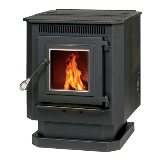
- Page 1 INSTALLATION & OPERATION MANUAL Pellet Stove MODELS 25-PDVC / 55-SHP10 / 55-TRP10 SAVE THESE Manufactured By: England’s Stove Works, Inc. PO Box 206 Monroe, VA 24574 9/6/2012 SAVE THESE INSTRUCTIONS ...
-
Page 2: Table Of Contents
TABLE OF CONTENTS Introduction Auger Bearings & Shafts ....... 17 Precautionary Statements ......3 Convection Blower ........ 17 Message from Us ........4 Combustion Blower ....... 17 Read Before Getting Started ....5 Vacuum Switch ........18 ... -
Page 3: Precautionary Statements
INSTALLATION & OPERATION MANUAL MODEL NUMBERS: 25-PDVC 55-SHP10 55-TRP10 Thank you for purchasing this product from a fine line of heating equipment. We wish you many years of safe heating pleasure with your new heating appliance. Save These Instructions. IMPORTANT: IF YOU HAVE A PROBLEM WITH THIS UNIT DO NOT RETURN IT TO THE DEALER. -
Page 4: Message From Us
A letter from our Technical Support Department: Thank you for purchasing this fine product from England’s Stove Works! England's Stove Works was started, and is still owned by, a family that believes strongly in a "Do It Yourself" spirit – that’s one reason you found this product at your favorite “Do It Yourself”... -
Page 5: Read Before Getting Started
BEFORE RE-STARTING YOUR UNIT Every time before pressing “ON” to start your unit – Be sure to remove all ashes (burnt or partially burnt) from your burn pot area! Wearing protective gloves and with the unit cool, remove the Wear Plate and dump the ashes, ensuring that the air holes are clear from debris. -
Page 6: Important Information
IMPORTANT INFORMATION Check local installation codes for your area. Call your Homeowner’s Insurance representative for inspection of your stove’s installation. Read and comply with the instructions in this manual. This unit should be tested (dry run) before loading pellets for 20 minutes. The stove should automatically shut itself off after the 20-minute dry run. -
Page 7: Unit Preparation
Do not allow paint, chemicals or construction dust on or near your unit. Do not allow liquid or ANY foreign materials on or inside your unit. Shut your unit down and cover it when painting, construction or similar activity is taking place. Wipe and clean your unit after any construction is done in your home, or if any foreign material gets on or inside your unit. -
Page 8: Flue System
IMPORTANT NOTICE: This unit must be properly installed to prevent the possibility of a house fire or “smoke-back.” The instructions must be strictly adhered to. Do not use makeshift methods or material which may compromise the installation. Your unit requires periodic maintenance and cleaning (refer to manual). Failure to maintain your unit may lead to a variety of problems, including but not limited to smoke spillage into the home. -
Page 9: Through The Ceiling
The through-the-wall installation is the least expensive and simplest installation. In a through-the-wall installation you should be mindful of the snowdrift line, as well as dead grass and leaves. We recommend a three foot (3’) minimum vertical rise on the inside or the outside of the dwelling. -
Page 10: Installation Diagrams
Freestanding Pellet Installation Caution: Follow the pipe manufacturer’s installation instructions and directions for passing through combustible walls and ceilings. Check local codes in your area. Illustration 1 Our Part AC-3000 is acceptable for through-the-wall installation; Must have minimum AC-3100 for 4000+ 3”... -
Page 11: Vent Termination Clearances
VENT TERMINATION CLEARANCES A) MIN. 4-FT CLEARANCE BELOW OR BESIDE ANY DOOR OR WINDOW THAT OPENS. B) MIN. 1-FT CLEARANCE ABOVE ANY DOOR OR WINDOW THAT OPENS. C) MIN. 2-FT CLEARANCE FROM ANY ADJACENT BUILDING. D) MIN. 7-FT CLEARANCE FROM ANY GRADE WHEN ADJACENT TO PUBLIC WALKWAYS. -
Page 12: Operating Instructions
OPERATING INSTRUCTIONS CAUTION: DO NOT OPERATE WITH THE DOOR OPEN. If door is left open (approximately) two minutes, unit will stop feeding and fire will go out. Do not burn trash (paper bags, etc.) in this unit. This stove has an induced draft system and is designed to operate continuously, as frequent shutdown is not required. -
Page 13: E-Codes
fire. Do not use the manual startup method if the igniter is working. NEVER place firestarter near the igniter. If you have continued problems with the Auto-Start Igniter, call Technical Support. E-Codes “E-Codes,” or Error Codes, are codes that will appear in the Heat Range and Blower Speed windows of the Control Board if your unit experiences problems. -
Page 14: Daily Operation
DAILY OPERATION Refueling the Unit Always press the “OFF” touch pad before refueling. This unit has a 40-lb. hopper, and should be refilled when the hopper level drops to three or four inches. Note: The hopper lid will be warm; therefore, you should always use some type of hand protection. NEVER place your hand near the auger while the stove is operating. -
Page 15: Daily
As with any maintenance concerning this unit, be sure the unit is “OFF” and has completed the Shut- Down cycle BEFORE beginning. Be aware that metal parts in the firebox can remain HOT long after the fire has gone out and EVEN after the Shut-Down cycle is complete. Always use extreme caution when handling potentially hot stove parts, even if you think they should be cold. -
Page 16: Monthly
Monthly Ash Removal The large baffle plate (12” x 13”) that rests above and behind the burn pot (refer to the exploded diagram in the rear of this manual – Illustration 6) should be removed monthly. This can be done by lifting up the plate and pulling it out. -
Page 17: Rear Panel Removal
MAINTENANCE CAUTION: UNPLUG THE UNIT PRIOR TO ANY SERVICE WORK! SEE EXPLODED DIAGRAM (ILLUSTRATION 6) FOR PARTS REFERENCE Parts Orders: (800) 516-3636 www.englanderstoves.com Questions: (800) 245-6489 NOTE: Visit our web site for downloadable maintenance sheets and/or a service video that details and illustrates the following maintenance tasks. -
Page 18: Vacuum Switch
Vacuum Switch This unit is equipped with Vacuum Shut Down Switches (Part # PU-VS and CU-VS), which help control various functions of the unit. If an operational error occurs in the unit, a switch will either stop the top (feed) auger or shut the unit off; if the unit turns off an E-1 Code (error code) will appear in the Heat Range and Blower Speed windows of the Control Board. -
Page 19: Hopper Lid Switch
Hopper Lid Safety Switch This unit is equipped with a hopper lid safety switch (Part # AC-HLSB) which is directly connected to the top auger motor. In the event the hopper lid is left open while the stove is in operation, the hopper lid switch will prevent the top auger from turning. -
Page 20: Control Board
Control Board The Control Board (Part # PU-CB04) is a digital read-out board. This board offers a wide variety of settings to operate the unit. This part can be removed from the unit by loosening the two outside screws and pulling the board back to the inside of the stove. The rear access panel should be removed prior to removing the control board. -
Page 21: Wiring Diagram
Illustration 4 PU-CB04 Control Board Wiring Diagram CAUTION: Moving Parts May Cause Injury. Do NOT Operate with Panel(s) Off. DANGER: Parts May Be Hot. Risk of Electric Shock. Disconnect Power Before Servicing Unit. If the unit or chimney connector IMPORTANT SAFETY NOTE: pipe “glows”... -
Page 22: Hopper Lid Latches
Adjusting Hopper Lid Latches The seals around the top of the pellet hopper are important to safe and efficient operation of the unit. The latches installed on these units are designed to pull the hopper lid tight against this seal. Over the course of operation as these seals “wear in”... -
Page 23: Accessory Items
ACCESSORY ITEMS The following accessories can be added to your unit at anytime after purchase; however, let the unit cool down before adding any accessories. Thermostat An external wall thermostat (such as our Part # PU-DTSTAT) can be used on our pellet units, as long as it is a low-voltage type that works with millivolt systems. -
Page 24: Parts List
REPLACEMENT PARTS, ACCESSORIES AND OPTIONS AC-GGK Glass Gasket Kit (gasket only, no glass) AC-DGKC Door Gasket Kit (#2 on diagram) AC-G9 9” x 9” Glass with Gasket (#3 on diagram) AC-SH Brass Door Spring Handle AC-SHN Nickel Door Spring Handle AC-MBSP Hi-Temperature Black Paint PU-AMS... -
Page 25: Exploded Parts Diagram
Pellet Stove – Exploded View Diagram Illustration 6 Unit Dimensions: 22 5/8" W x 28 1/4" H x 24" D Unit Weight: 290 lbs. (Approx. 13 ½” height from floor to center of exhaust) IMPORTANT! READ AND FOLLOW ALL INSTALLATION AND MAINTENANCE INSTRUCTIONS, INCLUDING CLEANING THE UNIT AS SPECIFIED, AND REPLACING GASKETS ANNUALLY, AND PARTS AS NEEDED. -
Page 26: Troubleshooting Guide
TROUBLE-SHOOTING GUIDE WARNING: TO AVOID ELECTRICAL SHOCK ALWAYS DISCONNECT THE UNIT FROM THE POWER SOURCE BEFORE ATTEMPTING ANY REPAIR. IF THIS GUIDE DOES NOT CORRECT THE PROBLEM CALL YOUR LOCAL DEALER OR OUR TECHNICAL SUPPORT AT 1-800-245-6489. Problem Cause Solution 1. -
Page 27: Serial Tag Sample
You may write your unit’s Manufacture Date and Serial Number in the blank spaces on this sample tag, for future reference. This sample tag also shows the safety info. such as UL/ULC testing standard, etc. for your local officials, or anyone else who may need reference IMPORTANT! READ AND FOLLOW ALL INSTALLATION AND MAINTENANCE INSTRUCTIONS, INCLUDING CLEANING THE UNIT AS SPECIFIED, AND REPLACING GASKETS ANNUALLY, AND PARTS AS NEEDED. -
Page 28: Warranty Details
Have this information on hand if you phone the factory or your dealer regarding this product. Retain for your files: Model Number __________________________ Date of Purchase ________________________ Date of Manufacture _________________ Serial #_____________________ LIMITED 5 YEAR WARRANTY FROM THE DATE OF PURCHASE TO THE ORIGINAL OWNER The manufacturer extends the following warranties: Five Year Period: 1. -
Page 29: Warranty Registration Form
WARRANTY REGISTRATION for England’s Stove Works Purchased by (Name) ______________________________________________ Address _________________________________________________________ City ________________________ State __________ Zip _________________ Telephone _______________________________________________________ Email Address ___________________________________________________ DEALER INFORMATION Purchased From (Dealer) ___________________________________________ Address _________________________________________________________ City ________________________ State __________ Zip _________________ UNIT INFORMATION (Please be sure to refer to sticker on back of manual or box to complete this section) Model Number _______________________ Purchase Date ____________________ Purchase Price _______________________... - Page 30 ...
- Page 31 MANUEL D'INSTALLATION ET D'UTILISATION NUMÉROS DE MODÈLE 25-PDVC 55-SHP10 55-TRP10 Nous vous remercions d'avoir acheté ce produit d'une excellente gamme, de matériel thermique. Nous vous souhaitons de nombreuses années de plaisir au chaud et sans danger avec votre nouvel appareil de chauffage Conserver ces directives.
- Page 32 Nous vous remercions d'avoir acheté cet excellent produit 'd'England’s Stove Works! England's Stove Works a été démarré et appartient toujours à une famille qui croit fortement à l'esprit « Faites le vous-même » – une raison pour laquelle vous trouvez ce produit dans votre magasin « Faites le vous-même » favori.
- Page 33 AVANT DE REDÉMARRER VOTRE APPAREIL Chaque fois, avant d'appuyer sur « ON » pour démarrer votre appareil – Veiller à retirer toutes les cendres (brûlées ou partiellement brûlées) de l'aire de la chambre de combustion! En portant des gants de protection et l'appareil étant froid, retirer la plaque d'usure et jeter les cendres, en vérifiant que les trous d'aération sont exempts de débris.
- Page 34 INFORMATION IMPORTANTE Vérifier les codes locaux d'installation de votre région. Appeler le représentant de votre assurance de propriétaire occupant pour une inspection de l'installation de votre poêle. Lire et suivre les de ce mode d’emploi. Cet appareil doit être testé (marche à vide) pendant 20 minutes avant de le charger en granules. Le poêle doit s'arrêter automatiquement après une marche à...
- Page 35 Ne pas laisser de peinture, de produits chimiques ou de poussière de construction près de votre appareil. Ne pas laisser de liquide ni QUELCONQUES matières étrangères sur ou dans l'appareil. Fermer et couvrir l'appareil lors d'activités de peinture, de construction ou autres du même ordre. Essuyer et nettoyer votre appareil après toute construction faite dans la maison ou si des matières étrangères sont déposées sur ou dans votre appareil.
- Page 36 AVIS IMPORTANT : Il faut installer correctement cet appareil pour prévenir la possibilité d'un incendie ou d'un « retour de fumée ». Il faut suivre strictement les directives. Ne pas utiliser de méthodes ou de matériel improvisés qui pourraient compromettre l'installation.
- Page 37 installation au sous-sol soit effectuée uniquement par un installateur professionnel. Pour les installations au sous-sol, il faut utiliser un tuyau de 3 po (75 mm)et un raccord pour l'air comburant extérieur et il faut conserver un espacement minimal de 900 mm (3 pi) depuis le sol jusqu'au tuyau évacuation du conduit hors de l'habitation.
- Page 38 Installation d'un poêle à granules autonome Attention : Suivre les directives du fabricant du tuyau et les instructions pour le passer au travers de murs et de plafonds combustibles. Vérifier les codes locaux de votre quartier. Illustration 1 Notre pièce AC- 3000 est acceptable pour une installation à...
- Page 39 DÉGAGEMENTS DES TERMINAISONS DES ÉVENTS A) DEGAGEMENT D’AU MOINS 1,22 M EN DESSOUS OU SUR LE COTE DE TOUTE PORTE OU FENETRE POUVANT S’OUVRIR. B) DEGAGEMENT D’AU MOINS 0,3 M AU-DESSUS DE TOUTE PORTE OU FENETRE POUVANT S’OUVRIR. C) DEGAGEMENT D’AU MOINS 0,61 M DE TOUT BATIMENT VOISIN. D) DEGAGEMENT D’AU MOINS 2,13 M A PARTIR DU NIVEAU DU SOL LORSQUE L’INSTALLATION JOUXTE LA VOIE PUBLIQUE.
- Page 40 DIRECTIVES D'UTILISATION ATTENTION : NE PAS UTILISER AVEC LA PORTE OUVERTE. Si la porte est laissée ouverte pendant deux minutes (environ), l'appareil cessera d'être alimenté et le feu s'éteindra. Ne pas brûler de rebuts (sacs de papier, etc.) dans cet appareil. Ce poêle dispose d'un système de tirage induit et est conçu pour fonctionner continuellement;...
- Page 41 E-Codes Les « E-Codes », ou codes d'erreur, sont des codes qui apparaissent dans les fenêtres du degré de chaleur et de la vitesse du ventilateur du tableau de commande si votre appareil présente des problèmes. Si un de ces codes est affiché, essayer d'abord de réinitialiser l'appareil en appuyant sur le bouton « ON » (une fois seulement).
- Page 42 UTILISATION QUOTIDIENNE Réalimentation en combustible Toujours appuyer sur la touche « OFF » avant de remettre du combustible. Cet appareil dispose d'une trémie de 18 kg (40 lb) qui doit être remplie lorsque son niveau baise à 75 ou 100 mm (3 ou 4 po). Note : Le couvercle de la trémie sera chaud;...
- Page 43 NOTE : Les directives ci-dessous relatives au nettoyage de l'aire de la chambre de combustion et de la plaque d'usure sont particulièrement importantes pour les fonctions de votre poêle. Le défaut de les suivre régulièrement peut entraîner un retour de combustion, endommager votre appareil et annuler votre garantie NETTOYAGE ET ÉLIMINATION DES CENDRES IMPORTANT : Bien que la quantité...
- Page 44 Nettoyage mensuel des cendres Il faut retirer chaque mois le grand déflecteur (305 mm x 330 mm [12 po x 13 po]) qui est suspendu au dessus et derrière la chambre de combustion (Consulter la vue éclatée au dos de ce manuel – Illustration 6).
- Page 45 ENTRETIEN : ATTENTION : DÉBRANCHER L'APPAREIL AVANT TOUT TRAVAIL D'ENTRETIEN! CONSULTER LA VUE ÉCLATÉE (ILLUSTRATION 6) POUR LA RÉFÉRENCE AUX PIÈCES Commandes de pièces : (800) 516-3636 www.englanderstoves.com Questions: (800) 245-6489 NOTE : Consulter notre site Web pour télécharger des feuilles d'entretien et ou une vidéo qui détaille et illustre les tâches d'entretien suivantes.
- Page 46 Commutateur d'aspiration Cet appareil dispose de commutateurs d'arrêt d'aspiration (Pièce # PU-VS et CU-VS), qui aide à commander les nombreuses fonctions de l'appareil. S'il y a une erreur d'opération dans l'appareil, un commutateur arrêtera la vis sans fin supérieure (alimentation) ou arrêtera l'appareil); dans le cas de l'arrêt de l'appareil, un code E-1 (code d’erreur) apparaîtra dans les fenêtres du degré...
- Page 47 Interrupteur de sécurité du couvercle de la trémie Cet appareil est également doté d’un interrupteur de sécurité du couvercle de la trémie (pièce AC-HLSB) qui est directement raccordé au moteur de la vis à granules supérieure. Dans l’éventualité où le couvercle de la trémie est laissé ouvert pendant que le poêle est en marche, l’interrupteur du couvercle de la trémie empêchera la vis à...
- Page 48 Tableau de commande Le panneau de commande (Pièce # PU-CB04) est un panneau à lecture numérique Ce tableau offre de nombreux réglages pour faire fonctionner l'appareil. Cette pièce peut être retirée de l'appareil en desserrant les deux vis extérieures et en la tirant vers l'intérieur du poêle. Le panneau d'accès arrière doit être enlevé...
- Page 49 Illustration 4 PU-CB04 Schéma du tableau de commande (câblage) ÉTIREUSE SUPÉRIEURE SOUFFLERIE DE COMBUSTION COMMUTATEUR DE SECURITÉ CÀBLE BLANC DE TRÉMIE CAPTEUR FUSIBLE 6 THERMIQUE FLEXIBLE SOUS VIDE HAUTE TEMP FLEXIBLE SOUS VIDE HAUTE TEMP CÀBLE NOIR COMMUTATEUR SOUS VIDE COMMUTATEUR SOUS VIDE IGNITEUR...
- Page 50 Ajustement des loquets de couvercle de trémie Les joints autour du couvercle de la trémie pour granules sont importants pour la sécurité d'un fonctionnement efficace de l'appareil. Les loquets posés sur ces appareils sont conçus pour tirer le couvercle de la trémie serré contre ce joint. Au cours de l'utilisation comme ces joints s'usent et se compressent, il faut tester la tension des loquets périodiquement et ajuster au besoin.
- Page 51 ACCESSOIRES Vous pouvez ajouter les accessoires suivants à votre appareil en tout temps; cependant, vous devez le laisser refroidir avant de le faire. Thermostat Vous pouvez installer un thermostat mural externe (comme notre pièce # PU-DTSTAT) sur nos appareils à granules de bois, pour autant qu'il fonctionne avec les systèmes à basse tension en millivolt. Après avoir débranché...
- Page 52 PIÈCES DE RECHANGE, ACCESSOIRES ET OPTIONS AC-GGK Kit de joint d'étanchéité de verre (joint uniquement) AC-DGKC Kit de joint d'étanchéité de porte (#2 sur le schéma) AC-G9 Verre 22,8 cm x 22,8 cm (9 po x 9 po) avec joint d'étanchéité (#3 sur le schéma) AC-SH Poignée de porte à...
- Page 53 Poêle à granules de bois – Vue éclatée Illustration 6 Dimensions de votre appareil à granules : L 58,4 cm x H 71,1 cm x P 43,3 cm (23 po x 28 po x 21 po) 131,6 kg (290 lb) (Hauteur de plancher au centre de l'évacuation, environ 34,3 cm (13 ½...
- Page 54 GUIDE DE DÉPANNAGE MISE EN GARDE : POUR ÉVITER UN CHOC ÉLECTRIQUE TOUJOURS DÉCONNECTER L'APPAREIL DE LA SOURCE DE COURANT AVANT DE COMMENCER UNE RÉPARATION. SI CE GUIDE NE VOUS PERMET PAS DE CORRIGER LE PROBLÈME, APPELER VOTRE VENDEUR LOCAL OU NOTRE SUPPORT TECHNIQUE AU 1-800-245-6489. Problème Cause Solution...
- Page 55 Vous pouvez inscrire la date de fabrication et le numéro de série de votre appareil dans les espaces prévus à cet effet sur cette étiquette, pour référence ultérieure. Cette étiquette comprend également des renseignements de sécurité, tels que la norme d’essai UL/ULC et autres, à l’intention de vos représentants locaux ou de toute autre personne qui peut en avoir besoin.
- Page 56 Avoir l'information en main lorsque vous téléphonez à l'usine ou à votre vendeur au sujet de ce produit. À conserver pour vos dossiers : Numéro de modèle__________________________ Date d'achat ________________________ Date de fabrication _________________ No de série_____________________ GARANTIE LIMITÉE À 5 ANS À...
- Page 57 ENREGISTREMENT DE GARANTIE pour England’s Stove Works Acheté par (Nom) ______________________________________________ Adresse _________________________________________________________ Ville ________________________ Province__________ Zip _________________ Téléphone _______________________________________________________ Adresse courriel ___________________________________________________ INFORMATION SUR LE VENDEUR Acheté de (Vendeur) ___________________________________________ Adresse _________________________________________________________ Ville ________________________ Province__________ Zip _________________ INFORMATION SUR L'APPAREIL (Veuillez vous assurer de consulter l'étiquette au dos de ce manuel ou sur la boîte pour remplir cette section) Numéro de modèle _______________________ Date d'achat ____________________ Prix d'achat _______________________...