Heat & Glo SL-550TR-E Installation Manual
Hide thumbs
Also See for SL-550TR-E:
- Owner's manual (91 pages) ,
- Owner's manual (89 pages) ,
- Owner's manual (86 pages)
Table of Contents
Advertisement
INSTALLER: Leave this manual with party responsible for use and operation.
OWNER: Retain this manual for future reference.
NOTICE: DO NOT discard this manual!
Models:
SL-550TR-E
SL-750TR-E
SL-550TR-IPI-E
SL-550TRLP-IPIE
SL-750TR-IPI-E
SL-750TRLP-IPIE
SL-950TR-IPI-E
This appliance may be installed as an OEM
installation in manufactured home (USA
only) or mobile home and must be installed
in accordance with the manufacturer's
instructions and the Manufactured Home
Construction and Safety Standard, Title 24
CFR, Part 3280 in the United States, or the
Standard for Installation in Mobile Homes,
CAN/CSA Z240 MH Series, in Canada.
This appliance is only for use with the type(s)
of gas indicated on the rating plate. This
appliance is not convertible for use with other
gases, unless a certifi ed kit is used.
In the Commonwealth of Massachusetts installation must be
performed by a licensed plumber or gas fi tter.
See Table of Contents for location of additional Commonwealth
of Massachusetts requirements.
Heat & Glo • SL-550/750TR-E, SL-550/750/950TR-IPI-E Installation Manual • 2118-910 Rev. C • 4/16
Installation Manual
Installation and Appliance Setup
WARNING:
FIRE OR EXPLOSION HAZARD
Failure to follow safety warnings exactly
could result in serious injury, death, or
property damage.
• DO NOT store or use gasoline or other fl am-
mable vapors and liquids in the vicinity of this
or any other appliance.
• What to do if you smell gas
- DO NOT try to light any appliance.
- DO NOT touch any electrical switch. DO
NOT use any phone in your building.
- Leave the building immediately.
- Immediately call your gas supplier from
a neighbor's phone. Follow the gas sup-
plier's instructions.
- If you cannot reach your gas supplier, call
the fi re department.
• Installation and service must be performed
by a qualifi ed installer, service agency, or the
gas supplier.
DANGER
DO NOT TOUCH GLASS
NEVER ALLOW CHILDREN
A barrier designed to reduce the risk of
burns from the hot viewing glass is provided
with this appliance and shall be installed for
the protection of children and other at-risk
individuals.
HOT GLASS WILL
CAUSE BURNS.
UNTIL COOLED.
TO TOUCH GLASS.
1
Advertisement
Table of Contents

Related Manuals for Heat & Glo SL-550TR-E


Summary of Contents for Heat & Glo SL-550TR-E
- Page 1 FIRE OR EXPLOSION HAZARD Failure to follow safety warnings exactly could result in serious injury, death, or Models: property damage. SL-550TR-E SL-750TR-E • DO NOT store or use gasoline or other fl am- mable vapors and liquids in the vicinity of this SL-550TR-IPI-E or any other appliance.
-
Page 2: Table Of Contents
Safety Alert Key: • DANGER! Indicates a hazardous situation which, if not avoided will result in death or serious injury. • WARNING! Indicates a hazardous situation which, if not avoided could result in death or serious injury. • CAUTION! Indicates a hazardous situation which, if not avoided, could result in minor or moderate injury. •... -
Page 3: Installation Standard Work Checklist
Date Installed: Customer: Location of Fireplace: Lot/Address: Installer: Dealer/Distributor Phone # Model (circle one): SL-550TR-E SL-750TR-E SL-550TR-IPI-E SL-750TR-IPI-E SL-950TR-IPI-E Serial #: SL-550TRLP-IPIE SL-750TRLP-IPIE WARNING! Risk of Fire or Explosion! Failure to install appliance according to these instructions could lead to a re or explosion. -
Page 4: Product Specifi C And Important Safety Information
Product Specifi c and Important Safety Information A. Appliance Certifi cation C. BTU Specifi cations Maximum Minimum Orifi ce MODELS: SL-550TR-E, SL-750TR-E, SL-550TR-IPI-E, Models Input Input Size SL-550TRLP-IPIE, SL-750TR-IPI-E, SL-750TRLP-IPIE, (U.S. or Canada) BTU/h BTU/h (DMS) SL-950TR-IPI-E SL-550TR-E (NG) 21,000... -
Page 5: Non-Combustible Materials Specifi Cation
E. Non-Combustible Materials Specifi cation Material which will not ignite and burn. Such materials are those consisting entirely of steel, iron, brick, tile, concrete, slate, glass or plasters, or any combination thereof. Materials that are reported as passing ASTM E 136, Standard Test Method for Behavior of Materials in a Vertical Tube Furnace at 750 ºC shall be considered non-combustible materials. -
Page 6: Requirements For The Commonwealth Of Massachusetts
Inspection Note: The following requirements reference various The state or local gas inspector of the side wall horizon- Massachusetts and national codes not contained in this tally vented gas fueled equipment shall not approve the document. installation unless, upon inspection, the inspector ob- serves carbon monoxide detectors and signage installed H. -
Page 7: Getting Started
Getting Started A. Design and Installation Considerations C. Inspect Appliance and Components Heat & Glo direct vent gas appliances are designed to • Carefully remove the appliance and components from operate with all combustion air siphoned from outside of the packaging. the building and all exhaust gases expelled to the outside. -
Page 8: Framing And Clearances
1015 8-13/16 8-13/16 16-5/16 16-5/16 25-3/4 30-3/4 12-7/8 15-3/8 15-7/8 15-7/8 6-5/8 6-5/8 2-3/16 2-3/16 30-1/16 33-9/16 Figure 3.1 Appliance Dimensions - SL-550TR-E, SL-550TR-IPI-E, SL-750TR-E, SL-750TR-IPI-E Heat & Glo • SL-550/750TR-E, SL-550/750/950TR-IPI-E Installation Manual • 2118-910 Rev. C • 4/16... - Page 9 Ø GAS LINE ACCESS Ø ELECTRICAL ACCESS SL-950TR-IPI-E Location Inches Millimeters 1218 1092 39-1/16 23-9/16 41-9/16 1056 3-9/16 6-7/8 30-7/8 41-7/8 1063 43-15/16 1117 8-13/16 16-5/16 37-3/4 18-7/8 15-11/16 6-5/8 2-3/16 37-9/16 Figure 3.2 Appliance Dimensions - SL-950TR-IPI-E Heat & Glo • SL-550/750TR-E, SL-550/750/950TR-IPI-E Installation Manual • 2118-910 Rev. C • 4/16...
- Page 10 FOLIO DECORATIVE FRONT 30-15/16 28-9/16 27-1/2 19-15/16 30-1/16 6-1/2 1-5/16 35-13/16 32-1/16 32-7/16 23-1/8 33-9/16 6-3/4 1-5/16 42-13/16 36-1/8 39-1/16 23-1/2 37-9/16 7-7/8 1-1/8 1087 CHATEAU/HALSTON DECORATIVE FRONTS 32-1/16 29-3/8 27-7/16 18-1/8 5-13/16 1-1/8 32-3/8 31-1/16 37-1/16 32-7/8 32-7/16 21-1/4 6-1/4 1-1/8 37-3/8...
- Page 11 CLEAN FACE DECORATIVE FRONTS 30-13/16 23-5/16 26-9/16 18-11/16 25-7/16 3-1/2 4-9/16 35-13/16 26-13/16 31-1/2 22-3/16 28-15/16 3-1/2 4-9/16 Figure 3.4 Appliance Dimensions - Clean Face Decorative Front Heat & Glo • SL-550/750TR-E, SL-550/750/950TR-IPI-E Installation Manual • 2118-910 Rev. C • 4/16...
-
Page 12: Clearances To Combustibles
Due to high temperatures, the appliance should be located out of traffi c and away from furniture and draperies. Models Min. Min. 59-1/2 62-1/4 16-1/4 48-1/2 68-3/4 15-1/16 7-1/2 7-1/8 SL-550TR-IPI-E SL-550TR-E 1067 1511 1118 1581 1232 1746 See Section 45-1/2 64-3/8 45-1/2 64-3/8 16-1/4 48-1/2... -
Page 13: Constructing The Appliance Chase
Appliance Appliance Opening Opening Opening Opening (Height) (Width) (Width) (Width) (Depth) (Depth) 8-5/8 34-3/4 16-1/4 16-1/4 SL-550TR-E SL-550TR-IPI-E 8-5/8 38-1/4 16-1/4 16-1/4 SL-750TR-E SL-750TR-IPI-E 1067 8-5/8 42 1/4 16-1/4 16-1/4 SL-950TR-IPI-E 1073 1245 * Adjust framing dimensions for interior sheathing (such as sheetrock) C** Add 12 inches for rear venting with one 90°... -
Page 14: Elevated Hearth Systems
D. Elevated Hearth Systems Use the table below to identify the hearth system that will be used. The table will also help identify effects on the various dimensions. Some hearth systems will elevate the appliance off the fl oor at a given dimension. For example, if appliance will be used with a Kenwood Cabinet with Base, the appliance will be elevated 9-1/4 in. -
Page 15: Termination Location And Vent Information
Termination Location and Vent Information A. Vent Termination Minimum Clearances 6 in. (minimum) up to 20 in. 18 in. minimum WARNING 152 mm/508 mm 457 mm 20 in. and over 0 in. minimum Fire Risk. Gas, Wood or Fuel Oil Maintain vent clearance to combustibles as Termination Cap specifi... -
Page 16: Chimney Diagram
B. Chimney Diagram H or i Electrical Service = VENT TERMINAL = AIR SUPPLY INLET = AREA WHERE TERMINAL IS NOT PERMITTED = 12 inches....clearances above grade, veranda, Covered Alcove Applications porch, deck or balcony (Spaces open only on one side and with an overhang) = 12 inches....clearance to window or door that may = 6 inches ... -
Page 17: Approved Pipe
C. Approved Pipe This appliance is approved for use with Hearth & Home Technologies DVP or SLP venting systems. Refer to Sec- tion 12.A for vent component information and dimensions. DO NOT mix pipe, fi ttings or joining methods from differ- ent manufacturers. -
Page 18: Use Of Elbows
D. Use of Elbows Diagonal runs have both vertical and horizontal vent as- pects when calculating the effects. Use the rise for the vertical aspect and the run for the horizontal aspect. See Figure 4.4. Two 45º elbows may be used in place of one 90º elbow. On 45º... -
Page 19: Use Of Flex Vent
F. Use of Flex Vent The fl ex vent must be supported with 3 in. the spacing between support intervals TERMINATION CAP CLEARANCE not exceeding 4 feet, with no more than 1/2 inch sag between supports. A support is required at each change in venting direction, and in any location where it is necessary to maintain the necessary clearance to combustibles. -
Page 20: Vent Diagrams
G. Vent Diagrams To replace the fi rst 90º starter elbow with two 45º elbows, refer to Figure 4.6. All other 90º elbows can be replaced with two 45º elbows. General Rules: • SUBTRACT 3 ft. from the total H measurement for each 90º... - Page 21 Top Vent - Horizontal Termination One Elbow Maximum Note: Use SLP Series components only. Minimum SL-550TR-E SL-550TR-E SL-950TR-IPI-E SL-550TR-IPI-E SL-750TR-IPI-E 90 Elbow * 2 ft. 610 mm 2 ft. 610 mm 1 ft. 305 mm Note: There MUST be a 25% reduction in total H when using 1/2 ft.*...
- Page 22 Top Vent - Horizontal Termination - (continued) Two Elbows Maximum Note: Use SLP Series V Minimum components only. SL-550TR-E SL-550TR-E SL-950TR-IPI-E SL-550TR-IPI-E SL-750TR-IPI-E 90 Elbow * 1/2 ft. 152 mm 1/2 ft. 152 mm 0 ft. 0 mm Note: There MUST be a 25% reduction in total H when using 1/2 ft.*...
- Page 23 Top Vent - Horizontal Termination - (continued) Three Elbows Maximum Note: Use SLP Series Minimum SL-550TR-E SL-750TR-E components only. SL-950TR-IPI-E Min. SL-550TR-IPI-E SL-750TR-IPI-E 90 Elbow ** 2 ft. 610 mm 2 ft. 610 mm 2 ft. 610 mm Note: There MUST be a 25% 1/2 ft.**...
- Page 24 Top Vent - Vertical Termination No Elbow Exhaust restrictor Instructions = 60 ft. Max. (18.3 m) 1. Install the exhaust restrictor over the center of the ex- haust outlet in the fi rebox. See Figure 4.12. 2. Center the exhaust restrictor in the open end of the Note: If installing a vertical vent/termination off the top of exhaust outlet and secure through the slots on the ex- the appliance, the optional vertical termination baffl...
- Page 25 Top Vent - Vertical Termination - (continued) SL-550TR-E SL-750TR-E SL-950TR-IPI-E SL-550TR-IPI-E SL-750TR-IPI-E MIN. Two Elbows H MAX. H MAX. H MAX. MIN. 90 Elbow 1-1/2 ft. 457 mm 1-1/2 ft. 457 mm 1 ft. 305 mm 1/2 ft. 152 mm 2 ft.
- Page 26 Top Vent - Vertical Termination - (continued) Three Elbows SL-550TR-E SL-750TR-E SL-950TR-IPI-E SL-550TR-IPI-E SL-750TR-IPI-E MIN. H MAX. H MAX. H MAX. MIN. 90 Elbow 1/2 ft. 152 mm 1/2 ft. 152 mm 0 ft. 0 mm 1/2 ft. 152 mm 1 ft.
- Page 27 Top Vent - Vertical Termination - (continued) MIN. MAX. MIN. MAX. MIN. Four Elbows 1-1/2 ft. 457 mm 4 ft. 1.2 m 4 ft. 1.2 m 4 ft. 1.2 m 3-1/2 ft. 1.0 m Note: Use SLP Series Maximum= 40 ft. (12.2 m) components only.
- Page 28 Figure 4.16 Rear Vent - Horizontal Termination = 9 in. (229 mm) Maximum One 45º Elbow For corner installation of models SL-550TR-E and SL-750TR-E ONLY Note: Use DVP Series components only. Note: Do not use a 45º elbow for SL-950TR-IPI-E. Use two 90º...
- Page 29 Rear Vent - Horizontal Termination - (continued) MAX. MIN. MAX. MAX. Two Elbows 1-1/2 ft. 457 mm Back to back elbows 1 ft. 305 mm 2-1/2 ft. 762 mm 3 ft. 914 mm 1 ft. 305 mm 3 ft. 914 mm 6 ft.
- Page 30 Rear Vent - Vertical Termination MIN. MAX. One Elbow 1 ft. 305 mm 3-1/2 ft. 1.1 m 2 ft. 610 mm 5-1/2 ft. 1.7 m Note: Use DVP Series 3 ft. 914 mm 7-1/2 ft. 2.3 m components only. H MAX. = 7-1/2 ft. (2.3 m) MAX.
- Page 31 Rear Vent - Vertical Termination - (continued) MIN. MAX. MAX. MAX. Three Elbows Back to back elbows 1-1/2 ft. 457 mm 1 ft. 305 mm 2-1/2 ft. 762 mm 1 ft. 305 mm 3-1/2 ft. 1.1 m 3 ft. 914 mm 6-1/2 ft.
- Page 32 OUTSIDE FACE OF Coaxial to Colinear Venting FIREPLACE The coaxial to colinear adapter (DV-46DVA-GCL) is ap- proved for installations into solid fuel masonry or factory EXHAUST VENT PIPE built fi replaces that have been installed in accordance with the National, Provincial, State and local building codes.
-
Page 33: Top Vent
Connecting the DV-46DVA-GCL Adapter to Appliance three screws. Top Vent • Attach one section of fl exible vent pipe to the stainless steel fl ex pipe with three self-tapping screws. • Remove top seal cap and insulation if equipped. See Section 11, “Appliance Setup.”... -
Page 34: Vent Clearances And Framing
Vent Clearances and Framing B. Wall Penetration Framing/Firestops A. Pipe Clearances to Combustibles Combustible Wall Penetration WARNING! Risk of Fire! Maintain air space clearance to vent. DO NOT pack insulation or other combustibles: Whenever a combustible wall is penetrated, you must frame a hole for the wall shield fi... -
Page 35: Ceiling Firestop/Floor Penetration Framing
C. Ceiling Firestop/Floor Penetra- tion Framing A ceiling fi restop MUST be used between fl oors and attics. • DVP pipe only - Frame an opening 10 in. by 10 in. (254 mm by 254 mm) whenever ATTIC ABOVE the vent penetrates a ceiling/fl oor (see Figure 5.3). -
Page 36: Appliance Preparation
Appliance Preparation A. Vent Collar Preparation CAUTION! Risk of Cuts, Abrasions or Flying Debris. Note: Actual unit may look different than the fi replace shown in this section. Wear protective gloves and safety glasses during instal- lation. Sheet metal edges are sharp. NOTICE: Once appliance is set up for top or rear venting, it CANNOT be changed at a later time. -
Page 37: Rear Vent
NOTICE: Once the seal cap has been removed it CANNOT be reattached. 2 SCREWS Figure 6.7 To attach the fi rst section of vent pipe, make sure to use the fi berglass gasket to seal between the fi rst Figure 6.10 Fold the center parts of the retaining band vent component and the outer fi... -
Page 38: Securing And Leveling The Appliance
C. Securing and Leveling the Appliance WARNING! Risk of Fire! Prevent contact with: • Sagging or loose insulation • Insulation backing or plastic • Framing and other combustible materials Block openings into the chase to prevent entry of blown- in insulation. Make sure insulation and other materials are secured. -
Page 39: Venting And Chimneys
Venting and Chimneys A. Assemble Vent Sections (DVP Pipe Only) Attach Vent to the Firebox Assembly Note: The end of the pipe sections with the lanced tabs will face toward the appliance. Attach the fi rst pipe section to the starting collar: •... -
Page 40: Assemble Slip Sections
Assemble Vent Sections B. Assemble Slip Sections • Slide the inner fl ue of the slip section into the inner fl ue (SLP Only) of the pipe section and the outer fl ue of the slip section To attach the fi rst vent component to the starting collars over the outer fl... -
Page 41: Secure The Vent Sections
C. Secure the Vent Sections D. Disassemble Vent Sections • Vertical runs originating off the top of the appliance, with • Rotate either section (see Figure 7.10) so the seams on no offsets, must be supported every 8 ft. (2.44 m) after both pipe sections are aligned as shown in Figure 7.11. -
Page 42: Vertical Termination Requirements
E. Vertical Termination Requirements Install Metal Roof Flashing • See minimum vent heights for various pitched roofs CAULK (Figure 7.12) to determine the length of pipe to extend through the roof. • Slide the roof fl ashing over the pipe sections extending through the roof as shown in Figure 7.13. -
Page 43: Horizontal Termination Requirements
Install Vertical Termination Cap F. Horizontal Termination Requirements • Attach the vertical termination cap by sliding the inner Heat Shield Requirements for Horizontal collar of the cap into the inner fl ue of the pipe section Termination while placing the outer collar of the cap over the outer WARNING! Risk of Fire! To prevent overheating and fi... - Page 44 Install Horizontal Termination Cap (DVP and Note: When using termination caps with factory-supplied heat shield attached, no additional wall shield fi restop is SLP Pipe) required on the exterior side of a combustible wall. WARNING! Risk of Fire! The telescoping fl ue section of the termination cap MUST be used when connecting vent.
-
Page 45: Electrical Information
Electrical Information Junction Box Installation A. General Information If the box is being wired from the INSIDE of the appliance: WARNING! Risk of Shock or Explosion! DO NOT wire 110-120 VAC to the valve or to the appliance wall switch. •... -
Page 46: Wiring Requirements
B. Wiring Requirements Standing Pilot Ignition System Wiring • The standing pilot ignition system wiring does not require Intellifi re Ignition System Wiring a 110-120 VAC supply to operate. See Figure 8.5. • Wire the appliance junction box to 110-120 VAC for •... - Page 47 IGNITION MODULE 3 VAC INTERMITTENT PILOT IGNITOR NOTE: 1. Ignition module, valve, pilot, and wall switch operate on 3 volts. 110-120 VAC is required at junction box unless equipped with battery back-up. TRANSFORMER WHITE 3 VAC ORANGE GROUND TO FIREPLACE PLUG IN CHASSIS WIRES...
- Page 48 PILOT THERMOPILE THERMOCOUPLE PIEZO THERMOSTAT WIRE ASSEMBLY WHITE VALVE Figure 8.5 Standing Pilot Ignition Wiring Diagram Wall Switch Installation for Fan (Optional) Temperature Sensor Wiring for Fan (Optional) If the box is being wired to a wall mounted switch for use If the fan will not be installed for operation with a wall with a fan (See Figure 8.6): switch, the temperature sensor will need to be installed.
-
Page 49: Gas Information
Gas Information A. Fuel Conversion C. Gas Connection • Make sure the appliance is compatible with available gas • Refer to Section 3 for location of gas line access in types. appliance. • Conversions must be made by a qualified service •... -
Page 50: Air Shutter Setting
When fi nished, tighten wing nut. NOTICE: If sooting occurs, provide more air by opening the air shutter. SHUTTER ADJUSTMENTS Figure 9.1 Air Shutter Shutter Settings Models SL-550TR-E 3/16 in. 3/16 in. SL-550TR-IPI-E SL-750TR-E 3/16 in. 3/16 in. SL-750TR-IPI-E SL-950TR-IPI-E 3/8 in. -
Page 51: Finishing
TOP AND SIDE SEAL JOINT BOTTOM 1 INCH (SHADED AREA) MAY BE COVERED WITH COMBUSTIBLE OR NON-COMBUTIBLE MATERIAL Figure 10.1 Facing Materials Models: SL-550TR-E, SL-750TR-E SL-550TR-IPI-E, SL-750TR-IPI-E Heat & Glo • SL-550/750TR-E, SL-550/750/950TR-IPI-E Installation Manual • 2118-910 Rev. C • 4/16... -
Page 52: Mantel And Wall Projections
NON-COMBUSTIBLE BOARD SHIPPED WITH APPLIANCE 1/2 in. 1/2 in. NON-COMBUSTIBLE ZONE Figure 10.4 Non-Combustible Zone Models: SL-550TR-E, SL-750TR-E Figure 10.7 Non-Combustible Zone SL-550TR-IPI-E, SL-750TR-IPI-E Models: SL-950TR-IPI-E Heat & Glo • SL-550/750TR-E, SL-550/750/950TR-IPI-E Installation Manual • 2118-910 Rev. C • 4/16... -
Page 53: Decorative Front Dimensions For Finishing
C. Decorative Front Dimensions for Finishing Only decorative fronts certifi ed for use with this appliance model may be used. Contact your dealer for a list of dec- orative fronts that may be used. Once you have deter- mined what kind of decorative front and fi nishing material FRONT FACE OF FIREPLACE is going to be used on the fi... -
Page 54: Appliance Setup
11 11 Appliance Setup A. Remove Fixed Glass Assembly D. Accessories WARNING! Risk of Asphyxiation! Handle fi xed glass Install approved accessories per instructions included assembly with care. Inspect the gasket to ensure it is with accessories. Contact your dealer for a list of ap- undamaged and inspect the glass for cracks, chips or proved accessories. -
Page 55: Lava Rock, Mineral Wool/Ember Placement
E. Lava Rock, Mineral Wool/Ember Placement F. Install Trim and/or Surround WARNING! Risk of Explosion! Follow ember placement • Install optional trim kits and/or surrounds using the instructions in manual. DO NOT place embers directly over instructions included with the accessory. burner ports. -
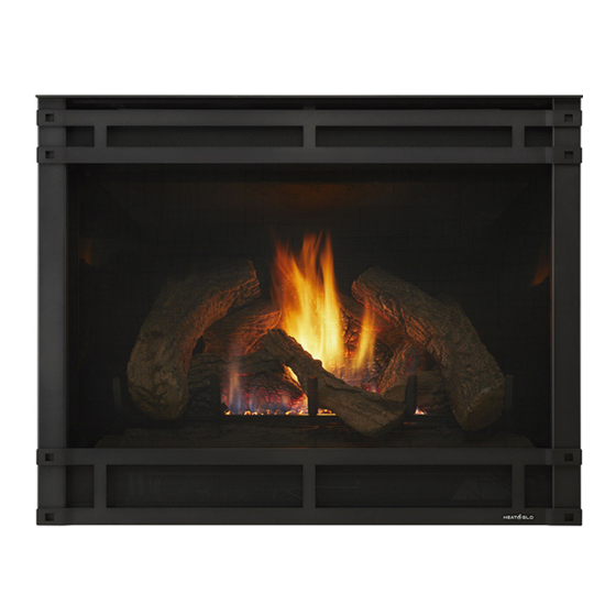
Page 56: Install The Log Assembly
G. Install the Log Assembly Log Set Assembly: LOGS-550-E, 750-E, 950-E Model: SL-550TR-E, 750TR-E, 950TR-E, If the gas logs have been factory installed they should not SL-550TV-E, SL-750TV-E, SL-950TV-E need to be positioned. If the logs have been packaged separately, refer to the following instructions. - Page 57 Log should touch lava rock retainer Log should touch lava rock retainer Pin hole Pin hole Mate shoulder screw with pin hole Mate shoulder screw with pin hole Figure 6 Figure 6 Figure 7 Figure 7 Log #3: Locate the pin hole on the underside of log #3. Mate the pin hole with the shoulder screw located on the burner top.
-
Page 58: Reference Materials
Reference Materials A. Vent Components Diagrams Effective Length Pipe 10-1/2 in. Inches Millimeters (267 mm) 45 ° Effective DVP4 Height/Length DVP6 DVP12 4-7/8 in. (124 mm) DVP24 10-7/8 in. DVP36 (276 mm) DVP Pipe (see chart) DVP48 1219 DVP45 (45º Elbow) DVP6A 3 to 6 76 to 152... - Page 59 A. Vent Components Diagrams (continued) Note: Heat shields MUST overlap by a minimum of 1-1/2 in. (38 mm). The heat shield is designed to be used on a wall 4 in. to 7-1/4 in. (102 mm to 184 mm) thick. If wall thickness is less than 4 in. (102 mm) the existing heat shields must be field trimmed.
- Page 60 A. Vent Components Diagrams (continued) 31 in. (787 mm) 13-1/4 in. (337 mm) 24-5/8 in. (625 mm) 27-1/2 in. 24-5/8 in. (699 mm) (625 mm) 13-1/4 in. (337 mm) RF6M RF12M Roof Flashing Multi-pak Roof Flashing Multi-pak 5 in. 13-3/4 in. 11-7/8 in.
- Page 61 A. Vent Components Diagrams (continued) 7-3/8 in. (187 mm) 1-1/2 in. (38 mm) 12 in. 305 mm 14 in. 17-3/4 in. (356 mm) (451 mm) 7-1/4 in. (184 mm) 6 in. 12-1/2 in. 152 mm (318 mm) 5-1/4 in. (133 mm) 12 in.
- Page 62 A. Vent Components Diagrams (continued) 8-1/8 in. 13 in. (206 mm) (330 mm) Effective Length 5-1/2 in. 8-3/8 in. 5-3/4 to 8-3/8 in. 140 mm 213 mm 146 to 213 mm 3° 87° 15 in. (381 mm) 10-1/2 in. 267 mm 10-7/8 in.
- Page 63 Optional Wire Harness DESCRIPTION PART NUMBER 13-5/8 IN. 10 FT PV Wire Harness PVI-WH10 346 mm EFFECTIVE LENGTH 32 IN. (813 mm) MIN. 20 FT PV Wire Harness PVI-WH20 35 IN. (889 mm) MAX. 40 FT PV Wire Harness PVI-WH40 60 FT PV Wire Harness PVI-WH60 12-1/2 IN.
- Page 64 A. Vent Components Diagrams (continued) Top View 6-1/4 IN. 159 mm 1-1/2 IN. 38 mm Front View Side View 2-1/4 IN. 15-1/2 IN. 57 mm 394 mm 4-3/4 IN. 121 mm 8 IN. 14 IN. 9-1/2 IN. 203 mm 356 mm 241 mm 5-1/4 IN.
- Page 65 A. Vent Components Diagrams (continued) 6-1/2 in. 165 mm 6-1/2 in. 165 mm 6-1/2 in. 165 mm 8-3/4 in. 9-1/4 in. 222 mm 6 in. 235 mm 152 mm 6-5/8 in. 168 mm 6-5/8 in. SLP45 168 mm 45° Elbow 9-7/8 in.
- Page 66 A. Vent Components Diagrams (continued) Note: Heat shields MUST overlap by a minimum of 1-1/2 in. (38 mm). The heat shield is designed to be used on a wall 4 in. to 7-1/4 in. (102 mm to 184 mm) thick. If wall thickness is less than 4 in. (102 mm) the existing heat shields must be field trimmed.
- Page 67 A. Vent Components Diagrams (continued) 12 in. 305 mm 14 in. 356 mm 12-1/2 in. 318 mm 10-9/16 in. 269 mm SLP-CCS-BK SLP-TVHW Cathedral Ceiling Vertical Support Box-Black Termination Cap 14-1/16 in. 13 in. 357 mm 330 mm 10-3/4 in. 273 mm 1-5/16 in.
- Page 68 COAXIAL to COLINEAR VENTING LINK-DV30B 768-380A DV-46DVA-GCL Flex Liner Kit Stainless Steel Flex Pipe Coaxial/Colinear Appliance Connector DVP-2SL Adapter DVP-FBHT DVP-FBHT SL-2DVP SLP90 Figure 12.11 Heat & Glo • SL-550/750TR-E, SL-550/750/950TR-IPI-E Installation Manual • 2118-910 Rev. C • 4/16...
-
Page 69: Accessories
B. Accessories Remote Controls, Wall Controls and Wall Switches Follow the instructions supplied with the control installed to operate your fi replace: For safety: • Install a switch lock or a wall/remote control with child protection lockout feature. • Keep remote controls out of reach of children. See your dealer if you have questions.