Advertisement
Quick Links
Advertisement

Related Manuals for Shindaiwa DGW400DM-C


Summary of Contents for Shindaiwa DGW400DM-C
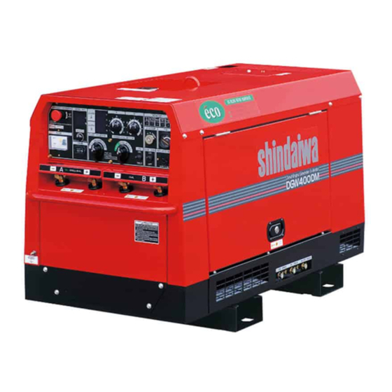
- Page 1 OWNER’S MANUAL DGW400DM-C...
- Page 2 1. Introduction Thank you for purchasing this Shindaiwa Sound Attenuated Diesel Engine Powered Welder/Generator. • This manual was created to help ensure the safe operation of this equipment. To avoid unnecessary accidents and/or repairs, it is strongly recommended that the user closely follow all the instructions contained in this manual.
- Page 3 2. Safety Guidelines Danger: Suffocation from exhaust fumes • Exhaust fumes from the engine used on this equipment contain many elements that have been proven to be harmful to humans. Do not operate this equipment without adequate ventilation. Danger: Electric Shock •...
- Page 4 Caution: Explosion • Do not use this equipment or charge the battery if the battery fluid level is lower than the LOWER level mark on the battery case. • The battery may emit highly explosive gases. Never expose it to flames or spark producing devices.
- Page 5 Caution, Danger, Warning and Operation Information Labels: Make sure all information labels are undamaged and readable. Immediately replace damaged or missing information labels. New labels are available from your local authorized Shindaiwa distributor or dealer. When ordering labels, use the following part numbers: 1 Suffocation from exhaust fumes (No.
- Page 6 4. Specifications Model DGW400DM - C Generating Method Rotating Field Rated Current (A) 390 @ 60% Duty Cycle, 302 @ 100% Duty Cycle Rated Voltage (V) 35.6 Rated Speed (rpm ) 3600 No Load Voltage (A) MAX 85 Single Current Adj. Range (A) 110 - 400 Welding Rod Diameter 5/64 –...
-
Page 7: Oil Filter
6. Parts DC METERS CURRENT ADJ. DIAL A ECO/SINGLE/DUAL SELECTOR SWITCH AC METERS CURRENT ADJ. DIAL B CV/CC SELECTOR SWITCH MONITOR LAMPS FUEL METER STARTER SWITCH 3-P BREAKER REMOTE CONTROL VOLTAGE ADJ. DIAL RECEPTACLE HOUR METER SLOW DOWN SWITCH WELDING TERMINALS A ENCLOSURE GROUNDING WELDING TERMINALS B TERMINAL... -
Page 8: Remote Control
7. Equipment 7-1 Eco Welding This equipment incorporates the Eco welding feature that allows welding operations at a reduced speed (2100 rpm) which results in lower noise levels, reduced fuel consumption and lower emission levels than with conventional welders. With the selector switch in the Eco position, welding can be done with up to 3/16” (5.0 mm) welding rod even though the engine is turning at a reduced speed. - Page 9 <Caution> • Do not plug the remote control box into any energized AC receptacle. • Do not connect other loads to the circuit that is powering the remote control. 7-4. Meters This equipment features reliable digital meters for welding voltage and current and alternator three phase output voltage and frequency DC Volt Meter and Ampere Meter for welding Side A and Side B.
- Page 10 Coolant/Water Temperature Monitor Lamp Danger: Injuries To avoid accidental contact with the cooling fan or fan belts, do not operate this equipment unless all doors are closed. Danger: Burns To avoid sustaining burns from hot vapor, do not open the radiator cap while operating or immediately after stopping this equipment Caution: Burns Due to extremely high temperatures, do not come in contact with the engine or muffler while...
- Page 11 If the engine oil pressure drops to an unsafe level during operation, the oil pressure monitor lamp will flash, and the engine will automatically shut down. If this occurs, check the engine oil level, and refill to the maximum level if needed. <Caution>...
- Page 12 (1) Grounding A qualified electrician should ensure grounding connections of 500 ohms or less at the following 3 points. • The earth grounding terminal in the output receptacle enclosure. • The Outer Enclosure of the equipment (enclosure grounding terminal). • The Outer Enclosure of the load(s).
- Page 13 The Earth Leakage Relay has activated Caution: Electric Shock / Injuries • If the Earth Leakage Circuit Breaker trips, disconnect all loads connected to the AC Generator prior to resetting it. When the earth leakage relay activates, the earth leakage indication lamp will turn ON and the circuit breaker lever will move to the tripped position (between ON and OFF).
-
Page 14: Side Door
7-8 AC Voltage Adjusting Dial This dial is used to adjust AC output voltage when necessary. Voltage Adjust Dial Decrease Increase <Caution> • Do not raise voltage beyond the rated capacity. Operating loads at higher than rated voltage can cause damage to the loads. •... - Page 15 <Caution> • If the equipment is not level, you cannot obtain an accurate oil level reading. • Do not overfill (above UPPER line) the engine oil. Excessive engine oil may damage the engine. Upper Level (5 1/2 Quarts.) Effective Level Lower Level (4 Quarts) •...
- Page 16 (1) Filling the Sub Tank 1 Remove the sub tank cap. 2 Add coolant to the FULL level. 3 Re-install the cap. (2) Filling the Radiator 1 Remove the top plate. Sub Tank 2 Remove the radiator cap. 3 Add coolant to the top. 4 Re-install the radiator cap.
-
Page 17: Fuel Strainer
• To help prevent solid contaminants from entering the fuel system, the fuel fill strainer should always be used. • To help prevent fuel spills, fill the fuel tank slightly less than full when refueling. TANK CAP FUEL INLET FUEL STRAINER 8-4 Checking Fuel, Engine Oil and Water Leakage Caution: Fire •... - Page 18 3. The battery acid specific gravity should never be allowed to fall below 1.23. This may be checked by using a hydrometer. Re-charge the battery if specific gravity is below 1.23. Replacing the battery 1. If battery replacement becomes necessary, remove the clamp and cable from the negative (-) post of the battery.
-
Page 19: Starter Switch
STARTER SWITCH SLOW SWITCH Restarting the engine after running out of fuel. This equipment is equipped with an automatic air bleed feature that allows easily restarting the engine after running out of fuel. If this machine runs out of fuel, use the following procedure for re-starting. - Page 20 10. Welding Operation 10-1 Selection – Welding Cable Always use welding cable of sufficient size for the desired welding amperage at the distance from the welder that the welding will be occurring. <Caution> • Welding cables should be used unstrained. The ampacity of the welding cables is decreased if the welding cables are coiled.
- Page 21 Welding Rod Eco (Single) Single Dual Welding Rod Welding Rod Welding Rod 5/64 –3/16 7/64 –5/16 5/64 –5/32 Welding Output Terminal Welding Output Terminal Welding Output Terminal Welding Output Terminal Semi-Automatic Wire Feeder Eco (Single) Single Dual Welding Wire Welding Wire Welding Wire MIG/MAG:.023 –.030 MIG/MAG: .023 –.045...
-
Page 22: Selector Switch
<Caution> • Never turn the output selector switch while welding. Operation of this switch during welding can cause damage to the switch. This equipment allows two operators to weld simultaneously with minimal affect on each other. Each operator can individually adjust their own welding current. CURRENT ADJ. - Page 23 (2) Semi-Automatic Wire Feeder 1. Turn the CV/CC selector switch to CV. 2. Turn the output selector switch to Eco, Single or Dual, according to the desired mode of operation. 3. Adjust voltage using the Current Adjust Dial A. Refer to the following table. Welding Voltage (V) / Amperage (A) at the dial position Position 1 Person...
- Page 24 1-Phase 120/240V Output Receptacle Maximum total single phase output from the 120/240 volt single phase receptacle is 4.3 kVA (4.3 kW), 18 amps at 240 V. 1-PHASE 120/240V RECEPTACLE 1-Phase 120V Output Receptacle Maximum total single phase output from the 120 volt duplex receptacle is 2.2 kVA (2.2 kW), 18 amps at 120 V.
- Page 25 Caution: Injuries • Do not plug loads into the receptacles until it has been verified that the load on/off switch is in the off position. <Caution> • The AC Volt meter reads three phase output voltage whenever the engine is operating, regardless of the position of the single phase and three phase breakers.
- Page 26 13. Checks and Maintenance Danger: Electric Shock, Injuries • Before performing any equipment check or maintenance, stop the engine and remove the engine key. The person performing the maintenance should always retain possession of the key. Caution: Fire, Burns • This equipment uses diesel (a flammable liquid) as a fuel.
- Page 27 Check Startup Every Every Every Every Every Check Items Check 50hrs 400 hrs 1000 2000 Check /Add Fuel Check/ Add Engine Oil Engine Oil Change after Engine Oil Filter after Change Check/Add Water/Coolant X or Water/Coolant Change year Clean Fuel Strainer after Change Fuel Filter Drain Water/Clean Fuel...
- Page 28 1. Oil Change Frequency Side Door Oil Fill First Time 50 hours Time and Every 100 hours thereafter Dipstick Procedure Oil Drain Plug 1. Remove the oil fill cap. 2. Remove the oil drain plug. <Caution> Oil will begin to drain as soon as the oil drain plug is loosened. Ensure there is adequate means to contain the used oil that is being drained.
- Page 29 3. Clean/Change Air Filter Element Frequency Clean at 50 hours and Every 100 hours Thereafter Replace Every 400 hours <Caution> • Clean more frequently, if it is used in dusty environment. Procedure 1. Loosen the wing bolt on the air cleaner cover and remove the air filter element. 2.
- Page 30 6. Reassemble 7. Open the fuel shut off valve and check for leaks. Open Close Fuel Shutoff Valve Retainer Ring 5. Drain Water from Fuel Tank Frequency Drain Water Every 200 hours Fuel Drain Plug Procedure 1. Unscrew the fuel drain plug. <Caution>...
- Page 31 4. After draining the water, reinstall the water drain plug. 5. Refill the coolant system with coolant/water to the upper edge of the radiator inlet. 6. Reinstall the radiator cap. 7. Reinstall the top plate. Radiator Cap Top Plate Radiator Fill 14.
- Page 32 Follow the guidelines below when performing any troubleshooting. If you cannot rectify the problem by using this troubleshooting guide, contact the nearest authorized distributor. Symptoms Possible Cause Corrective Actions Starter motor will not 1. Weak Battery 1. Recharge Battery turn over 2.
- Page 33 2 010 Ⓒ...