Table of Contents
Advertisement
Advertisement
Table of Contents

Related Manuals for Kyocera Mita DP-100


Summary of Contents for Kyocera Mita DP-100
- Page 1 DP-100 SERVICE MANUAL Published in Feb. ’03 3HK70760...
-
Page 2: Safety Precautions
Safety precautions This booklet provides safety warnings and precautions for our service personnel to ensure the safety of their customers, their machines as well as themselves during maintenance activities. Service personnel are advised to read this booklet carefully to familiarize themselves with the warnings and precautions described here before engaging in maintenance activities. - Page 3 Safety warnings and precautions Various symbols are used to protect our service personnel and customers from physical danger and to prevent damage to their property. These symbols are described below: DANGER: High risk of serious bodily injury or death may result from insufficient attention to or incorrect compliance with warning messages using this symbol.
-
Page 4: Installation Precautions
1. Installation Precautions WARNING • Do not use a power supply with a voltage other than that specified. Avoid multiple connections to one outlet: they may cause fire or electric shock. When using an extension cable, always check that it is adequate for the rated current..................... •... -
Page 5: Specifications 1
2. Precautions for Maintenance WARNING • Always remove the power plug from the wall outlet before starting machine disassembly....• Always follow the procedures for maintenance described in the service manual and other related brochures............................• Under no circumstances attempt to bypass or disable safety features including safety mechanisms and protective circuits. - Page 6 • Do not pull on the AC power cord or connector wires on high-voltage components when removing them; always hold the plug itself....................... • Do not route the power cable where it may be stood on or trapped. If necessary, protect it with a cable cover or other appropriate item.
-
Page 7: Table Of Contents
CONTENTS 1-1 Specifications 1-1-1 Specifications ............................1-1-1 1-1-2 Parts names and their functions ......................1-1-2 1-1-3 Machine cross section .......................... 1-1-3 1-1-4 Drive system ............................1-1-4 1-2 Installation 1-2-1 Unpacking and installation ........................1-2-1 1-3 Troubleshooting 1-3-1 Original misfeed detection ........................1-3-1 (1) Original misfeed indication ...................... -
Page 8: Specifications
1-1-1 Specifications Original feed system ...... Automatic feed Originals ......... Sheets Original weights ......50 – 120 g/m " × 14" – 5 " × 8 Original sizes ........Folio – A5R/8 " No. of originals ....... Up to 50 sheets (50 – 80 g/m For art paper, set one sheet at a time. -
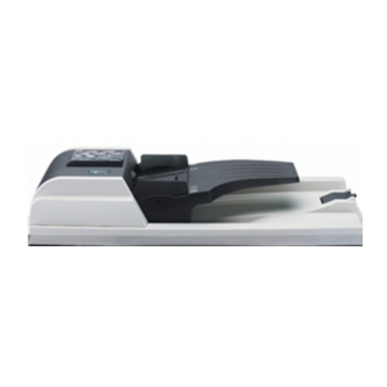
Page 9: Parts Names And Their Functions
1-1-2 Parts names and their functions Figure 1-1-1 1 Original table 2 Original insert guides 3 DP opening/closing lever 4 Original eject cover 5 DP original cover 6 Ejection extension 1-1-2... -
Page 10: Machine Cross Section
1-1-3 Machine cross section Original path Figure 1-1-2 Machine cross section 1-1-3... -
Page 11: Drive System
1-1-4 Drive system As viewed from machine front Figure 1-1-3 1 Forwarding gear 18 7 Gear 65/16 2 Feed drive gear 20 8 Feed drive gear 20 3 Feed gear 18 9 Conveying gear 33 4 Feed gear 20 0 Conveying V pulley 5 Feed drive gear 20 ! Conveying belt 6 Original feed motor (gear) -
Page 12: Unpacking And Installation
1-2-1 Unpacking and installation Figure 1-2-1 Unpacking 1 Document processor 2 Installation guide 3 Caution label 4 Plastic bag 5 Front pad 6 Rear pad 7 Outer case 8 Plastic sheet 9 Bottom plate 0 Supports ! Upper plate 1-2-1... - Page 13 Procedure 1. Remove all of the components to the document processor from the box. CAUTION Be sure to hold both sides of the document processor when carrying it, as shown in the illustration. Be particularly careful NOT to touch the guide film or the thin white surface indicated by the A in the illustration.
- Page 14 4. Attach the document processor to the copier. CAUTION Be sure that the connection cable does not get caught between the document processor and the copier when attaching the document processor to the copier. Connection cable Figure 1-2-5 5. Gently close the document processor. Document processor Figure 1-2-6...
- Page 15 CAUTION Be sure to tighten the pins securely when connecting the cable. Pins Figure 1-2-8 7. Turn the main switch to the copier back ON ( | ). Warm up will begin. “1” will appear on the operation panel and the Start indicator will light when the copier is in a copy-ready state.
-
Page 16: Original Misfeed Detection
1-3-1 Original misfeed detection (1) Original misfeed indication When an original jams, the machine immediately stops operation and a message is shown on the copier operation panel. To remove the jammed original, open the DP or the DP original cover. Also if the main switch on the copier is turned on with an original set on the original table, the original jam display appears. -
Page 17: Paper Misfeed Detection Conditions
(2) Paper misfeed detection conditions Section Jam code Description Conditions No original feed When the main switch is turned on, the machine detects acti- vation of the DP timing switch. The machine cannot detect activation of the DP timing switch even after 600 ms elapses since the start of primary paper feed and cannot detect it at the same timing even after four times of retry. -
Page 18: Original Misfeeds
(3) Original misfeeds Problem Causes/check procedures Corrective measures A piece of paper torn from Remove any found. An original jams an original is caught when the main around the DP timing switch is turned on. switch. Defective DP timing Run maintenance item U244 and turn DP timing switch on and switch. -
Page 19: Image Formation Problems 1
1-3-2 Image formation problems (1) There is a regular error (2) There is a regular error between the centers of between the leading the original and copy edges of the original image. and copy image. See page 1-3-5 See page 1-3-5 1-3-4... - Page 20 (1) There is a regular Causes error between the 1. Misadjusted DP center line. centers of the original and copy image. Check procedures/corrective measures Causes Readjust the DP center line (see page 1-4-10). 1. Misadjusted DP center line. (2) There is a regular Causes error between the 1.
-
Page 21: Electrical Problems
1-3-3 Electrical problems Problem Causes Check procedures/corrective measures Defective original feed mo- Check for continuity across the coil. If none, replace the original The original feed tor coil. feed motor. motor does not op- The connector terminals of Reinsert the connector. Also check for continuity within the con- erate. -
Page 22: Mechanical Problems
1-3-4 Mechanical problems Problem Causes/check procedures Corrective measures The surfaces of the DP forwarding pulley, Check and clean them with isopropyl alco- No primary original DP feed pulley or pad are dirty with paper hol if they are dirty. feed. powder. -
Page 23: Precautions For Assembly And Disassembly
1-4-1 Precautions for assembly and disassembly (1) Precautions • Be sure to turn the main switch off and disconnect the power plug of the copier before starting disassembly. • When handling PCBs, do not touch connectors with bare hands or damage the board. •... -
Page 24: Assembly And Disassembly
1-4-2 Assembly and disassembly (1) Detaching and refitting the original table, front cover, rear cover and DP original cover Procedure 1. Detach each hook and then remove the original cover, front cover, rear cover and DP original cover. Front cover DP original table Rear cover DP original cover... -
Page 25: Detaching And Refitting The Dp Forwarding Pulley And Dp Feed Pulley
(2) Detaching and refitting the DP forwarding pulley and DP feed pulley Follow the procedure below to clean or replace the DP forwarding or DP feed pulley. Procedure 1. Open the DP original cover. 2. Remove the stopper ring. 3. Remove the bush and then the DP forwarding pulley unit. - Page 26 • Detaching the DP forwarding pulley 3. Remove the stopper ring. 4. Pull out the forwarding shaft and then remove the DP forwarding pulley. • Detaching the DP feed pulley 5. Remove the two stopper rings. 6. Pull out the feed shaft and then remove the DP feed pulley.
-
Page 27: Detaching And Refitting The Dp Conveying Roller And Dp Eject Roller
(3) Detaching and refitting the DP conveying roller and DP eject roller Follow the procedure below to clean or replace the DP conveying roller and DP eject roller. Procedure 1. Remove the two connectors. 2. Remove the three screws and the terminal Screws and then remove the paper feed housing. -
Page 28: Conveying Gear
4. Remove the conveying belt. • Detaching the DP conveying roller 5. Remove the conveying V pulley and then remove the bush. 6. Remove the stopper ring and then remove the conveying gear 33 and bush. 7. Remove the DP conveying roller from the paper feed housing. -
Page 29: Adjustment The Maintenance Mode
1-4-3 Adjustment the maintenance mode (1) Adjusting the DP magnification Adjust magnification in the auxiliary scanning direction if magnification is incorrect when the DP is used. U065 (See the service manual U070 of the copier.) Caution: Before making the following adjustment, ensure that the above adjustments have been made in maintenance mode. Procedure Main scanning direction... -
Page 30: Adjusting The Dp Leading Edge Registration
(2) Adjusting the DP leading edge registration Perform the following adjustment if there is a regular error between the leading edge of the original and the copy image. U034 U066 (See the service manual (See the service manual U071 of the copier.) of the copier.) Caution: Before making the following adjustment, ensure that the above adjustments have been made in maintenance mode. -
Page 31: Adjusting The Dp Trailing Edge Registration
(3) Adjusting the DP trailing edge registration Perform the following adjustment if the original scanning end position is not correct when the DP is used. Caution: If the copy image looks like copy example 2, clean the DP original scanning section. Procedure Start Enter maintenance mode. -
Page 32: Adjusting The Dp Center Line
(4) Adjusting the DP center line Perform the following adjustment if there is a regular error between the centers of the original and the copy image. U034 U067 (See the service manual (See the service manual U072 of the copier.) of the copier.) Caution: Before making the following adjustment, ensure that the above adjustments have been made in maintenance mode. -
Page 33: Adjusting The Margins For Scanning The Original From The Dp
(5) Adjusting the margins for scanning the original from the DP Perform the following adjustment if margins are not correct. U402 U403 (See the service manual (See the service manual U404 of the copier.) of the copier.) Caution: Before making the following adjustment, ensure that the above adjustments have been made in maintenance mode. Procedure DP leading edge margin (3 ±... -
Page 34: Mechanical Construction
2-1-1 Mechanical construction (1) Original feed section The DP consists of the components shown in Figure 2-1-1. An original placed on the original table is conveyed the original across the DP contact glass in synchronization with the copier scanning operation. When a primary original feed starts, the original feed motor (OFM) is turned on in the forward direction, the DP forwarding pulley rotates to forward an original, and then the DP feed pulley advances original feed. - Page 35 DPTSW YC3-1, 2, 3, 4 YC2-5 DPDPCB Figure 2-1-2 DP block diagram 2-1-2...
-
Page 36: Original Feed Timing
(2) Original feed timing Primary original Secondary original feed start feed start DPTSW: On DPTSW: Off DPODSW YC2-8 DPTSW YC2-5 Fwd. Stop Stop Stop OFM YC3-1, 2, 3, 4 Rev. OFM drive pulse count PC_ORGF PC_ORGR PC4- PC_ORGR OVSYNC (Copier) Timing chart 2-1-1 A: When a primary feed starts, the original feed motor (OFM) continues forward rotation (slowup) for the period of the specified number of pulses (PC1) to rotate the DP forwarding pulley and the DP feed pulley. -
Page 37: Electrical Parts Layout
2-2-1 Electrical parts layout Figure 2-2-1 1. DP driver PCB (DPDPCB) ......Controls electrical components of the DP. 2. DP original cover switch (DPOCSW) ... Detects the opening and closing of the DP original cover. 3. DP original detection switch (DPODSW) ..Detects the presence of original on the DP; resets original misfeed detection. -
Page 38: Dp Driver Pcb
2-3-1 DP driver PCB DPDPCB 24 V DC DPDETN OFM A OFM A Motor OFM _A OFM _A driver OFM B OFM B OFM _B OFM _B (U1) 5 V DC 5 V DC 24 V DC 24 V DC 5 V DC Copier PGND... - Page 39 Figure 2-3-2 DP driver PCB silk-screen diagram 2-3-2...
- Page 40 Terminals (CN) Voltage Remarks Frame ground 24 V DC 24 V DC supply 5 V/0 V DC DPOCDSW DP open/close 0 V/5 V DC DPOCSW DP original cover open/close 0 V/5 V DC DPTSW ON/OFF output 0 V/5 V DC DPODSW ON/OFF output 0 V DC DP installed/not installed detection signal...
- Page 41 2-4-1...
- Page 42 2-4-2...
- Page 43 2-4-3...
-
Page 44: Connection Diagram
Connection diagram 2-4-4... - Page 45 Av. 16 de Septiembre #407 Col. Santa Inés, 02130 Azcapotzalco México, D.F. México TEL : (55) 5383-2741 FAX : (55) 5383-7804 ©2003 KYOCERA MITA CORPORATION http://www.kyoceramita.com is a trademark of Kyocera Corporation is a registered trademark of KYOCERA MITA CORPORATION Printed in U.S.A.