Sign In
Upload
Manuals
Brands
YOKOGAWA Manuals
Measuring Instruments
wt3000
YOKOGAWA wt3000 Manuals
Manuals and User Guides for YOKOGAWA wt3000. We have
3
YOKOGAWA wt3000 manuals available for free PDF download: User Manual
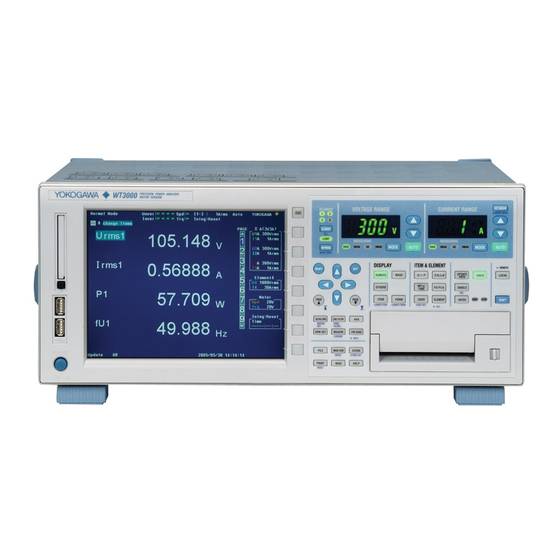
YOKOGAWA wt3000 User Manual (384 pages)
precision power analyzer
Brand:
YOKOGAWA
| Category:
Measuring Instruments
| Size: 5 MB
Table of Contents
Product Registration
2
Checking the Contents of the Package
5
Standard Accessories
7
Safety Precautions
9
Conventions Used in this Manual
11
Flow of Operation
12
Table of Contents
13
Chapter 1 Names and Functions of Parts
17
Front Panel, Rear Panel, and Top Panel
17
Front Panel, Rear Panel, and Top Panel
18
Setup Menu Display Key and Execution Key
19
Input Element
19
Display Screen
26
Chapter 2 Functional Description
27
System Configuration and Block Diagram
27
Block Diagram
28
Measurement Modes and Measurement Functions
29
Computation
30
Integration
47
Waveform Display
50
Trend, Bar Graph, and Vector Displays
57
Waveform Computation and FFT
59
Voltage Fluctuation and Flicker and Cycle-By-Cycle Measurements
60
Saving and Loading Data and Other Functions
61
Chapter 3 Before Starting Measurements
65
Handling Precautions
65
Installing the Instrument
66
Connecting the Power Supply
68
Turning ON/OFF the Power Switch
69
Wiring Precautions
71
Assembling the Adapter to be Connected to the Voltage Input Terminal
74
Wiring for Making Accurate Measurements
76
Guide for Selecting the Method Used to Measure the Power
77
Wiring the Circuit under Measurement for Direct Input
78
Wiring the Circuit under Measurement When Using the Current Sensor
81
Wiring the Circuit under Measurement When Using the VT/CT
85
Setting the Date/Time
88
Initializing the Settings
90
Entering Values and Character Strings
92
Entering Character Strings on the USB Keyboard
96
Switching the Measurement Mode and Display
98
Displaying the Setup Parameter List
103
Selecting the Message Language
105
Setting the USB Keyboard Language
107
Chapter 4 Measurement Conditions
108
Selecting the Wiring System
108
Selecting Independent Setting of Input Elements
111
Setting the Measurement Range When Using the External Current Sensor
119
Setting the Scaling Function When Using VT/CT
122
Selecting the Crest Factor
125
Setting the Measurement Period
126
Selecting the Input Filter
129
Selecting the Averaging Function
131
Selecting the Data Update Rate
134
Hold and Single Measurement
136
Chapter 5 Power Measurement
137
Displaying Numeric Data and Changing the Displayed Items
137
Selecting the Voltage/Current Mode (RMS, MEAN, DC, or RMEAN)
145
Selecting the Frequency Measurement Source
146
Setting the User-Defined Function
148
Setting MAX Hold
153
Measuring the Average Active Power
155
Setting the Equation for Efficiency
156
Setting the Wiring, Efficiency, and Two-Wattmeter Method Compensations
158
Setting the Equations for Apparent Power, Reactive Power, and Corrected Power
161
Selecting the Display Format of the Phase Difference
164
Integration
166
Setting the Manual Integration
171
Setting the Normal Integration and Repetitive Integration
174
Setting the Real-Time Integration and Real-Time Repetitive Integration
177
Turning ON/OFF the Integration Auto Calibration
181
Chapter 6 Waveform Display
182
Selecting the Waveform to be Displayed
184
Setting the Time Axis
186
Setting the Trigger
188
Zooming Vertically and Moving the Vertical Position
195
Waveform Display on Divided Windows
196
Selecting the Display Interpolation and Graticule
201
Turning ON/OFF the Scale Value and Waveform Label
202
Cursor Measurement
204
Chapter 7 Trend Display
207
Selecting the Trend Data to be Displayed
209
Selecting the Trend Display Target
211
App
211
Setting the Time Axis
214
Setting the Scale
216
Displaying Trends on Divided Windows
218
Value and Waveform Label
220
Restarting the Trend
222
Cursor Measurement
223
Chapter 8 Storing and Recalling Data and Saving the Stored Data
226
Setting the Store Mode
226
Setting the Numeric Data and Waveform Display Data to be Stored
228
Setting the Store Count, Store Interval, Store Reservation Time, and Alert Indication of Internal Memory Initialization
232
Storing Data
236
Saving the Stored Data
239
Recalling the Stored Data
246
Chapter 9 Saving and Loading Data
248
PC Card and USB Memory
248
Formatting the Storage Media
250
Saving Setup Parameters, Waveform Display Data, Numeric Data, Waveform Sampling Data
253
Saving the Screen Image Data
267
Loading Setup Parameters
271
Specifying the File to be Displayed, Displaying File Properties, and Selecting File Attributes
274
Deleting Files
277
Copying Files
280
Renaming Files or Directories and Creating Directories
284
Chapter 10 Other Functions
288
Zero-Level Compensation
288
NULL Function
289
Selecting the Sampling Frequency
291
Selecting the Display Font
292
Selecting the Screen Brightness
294
Setting the Display Color
295
Setting the Key Lock and Shift Lock Function
298
Help Function
300
Master/Slave Synchronization Measurement
301
Chapter 11 Troubleshooting, Maintenance, and Inspection
304
Troubleshooting
304
Error Messages and Corrective Actions
305
Self-Test
310
Checking the System Condition
312
Replacing the Power Fuse
313
Recommended Replacement Parts
314
Chapter 12 Specifications
315
Input Section
315
Display
316
Measurement Functions (Measurement Items) Related to Normal Measurement
317
Accuracy
319
Functions
323
Input/Output of the Master/Slave Synchronization Signal
327
External Clock Input
327
Storage
328
USB PERIPHERAL Interface
328
GP-IB Interface
329
Safety Terminal Adapter
329
General Specifications
330
External Dimensions
332
Appendix
333
Appendix 1 Symbols and Determination of Measurement Functions
333
Appendix 2 List of Initial Settings and Display Order of Numeric Data
341
Appendix 4 Power Basics (Power, Harmonics, and RLC of AC Circuits)
348
Appendix 5 for Making Accurate Measurements
356
Appendix 6 Setting the Measurement Period
358
Appendix
366
Appendix 8 Compensation Function
366
Appendix 9 Key Assignments of the USB Keyboard
368
Measurement Mode
373
Measurement Functions that Can be Measured in each Measurement Mode
374
Operands of User-Defined Functions that Can be Used in each Measurement Mode
376
Advertisement
YOKOGAWA wt3000 User Manual (255 pages)
Precision power analyzer expansion function
Brand:
YOKOGAWA
| Category:
Measuring Instruments
| Size: 15 MB
Table of Contents
Safety Precautions
3
Conventions Used in this Manual
4
Table of Contents
5
Chapter 1 Motor Evaluation Function (Motor Version)
8
Names and Functions of Parts of the Motor Evaluation Function
8
Applying Signals of Rotating Speed and Torque
9
Selecting the Type of the Revolution and Torque Signals
11
Selecting the Analog Range
14
Selecting the Line Filter and Synchronization Source
17
Setting the Pulse Range, Pulse Count, and Pulse Rating
19
Setting the Scaling Factor and Unit
24
Setting the Motor and Frequency Measurement Source for Computing the Sync Speed and Slip
28
Computing the Motor Efficiency and Total Efficiency
31
Specifications of the Motor Evaluation Function
32
Chapter 2 Built-In Printer (Option)
34
Names and Functions of Parts of the Built-In Printer
34
Loading the Roll Paper and Feeding the Paper
35
Printing Screen Images on the Built-In Printer
40
Printing Numeric Data Lists on the Built-In Printer
42
Auto Print
45
Built-In Printer Specifications
51
Chapter 3 D/A Output and Remote Control (Option)
52
Part Names and Functions of D/A Output
52
Functional Description
53
Setting the D/A Output
54
Types of Measurement Functions
57
Setting the D/A Zoom
61
Remote Control
63
D/A Output and Remote Control Specifications
65
Chapter 4 RGB Video Signal (VGA) Output (Option)
66
Names and Functions of the Parts of the RGB Video Signal (VGA) Output
66
RGB Video Signal (VGA) Output Specifications
67
Chapter 5 Ethernet Communications (Option)
68
Connecting to the Network
68
Setting TCP/IP
69
Saving Setup, Waveform Display, Numeric, and Image Data to the FTP Server (FTP Client Function)
76
Printing Screen Images on a Network Printer
79
Sending E-Mail
83
Accessing the WT3000 from a PC or Workstation (FTP Server Function)
86
Setting of the Time Difference from GMT or SNTP
90
Checking the Ethernet Communication Function (Option) Availability and MAC Address
92
Setting the FTP Passive Mode and LPR/SMTP Timeout
94
Ethernet Interface Specifications
95
Chapter 6 Delta Computation (Option)
97
Setting the Delta Computation
97
Determination of Delta Computation
100
Delta Computation Specifications
101
Chapter 7 Harmonic Measurement in Normal Measurement Mode (Option)
111
Setting the Measurement Mode and Displaying Numeric Data
111
Setting the Number of Displayed Items, Page Scrolling the Display
113
Changing the Displayed Items of Numeric Data
117
Selecting the PLL Source
123
Setting the Measured Order
126
Selecting the Distortion Factor Equation
128
Setting the Anti-Aliasing Filter
129
Displaying the Bar Graph and Making Cursor Measurements
131
Displaying Vectors
136
Harmonic Measurement Specifications
139
Chapter 8 Wide Bandwidth Harmonic Measurement (Option)
147
Wide Bandwidth Harmonic Measurement Function
147
Various Settings Related to Wide Bandwidth Harmonic Measurement
148
Selecting the Wide Bandwidth Harmonic Measurement Mode and Displaying Numeric Data
149
Turning ON/OFF the Timeout Warning Display of the PLL Lock
151
Wide Bandwidth Harmonic Measurement Specifications
152
Chapter 9 IEC Harmonic Measurement (Option)
160
Selecting the IEC Harmonic Measurement Mode
160
Selecting the Measured Source
161
Selecting the Voltage/Current Grouping
162
IEC Harmonic Measurement Specifications
164
Chapter 10 Waveform Computation (Option)
171
Setting the Waveform Computation Mode
171
Setting the Waveform Equation
172
Setting the Scale, Unit, and Label of the Computed Waveform
176
Waveform Computation Function Specifications
180
Chapter 11 FFT (Option)
181
FFT Function
181
Various Settings Related to FFT
184
Setting the FFT Mode
185
Selecting the Power Spectrum to be Displayed, Selecting the FFT Source, and Setting the Label
187
Setting the Number of Computed Points and Time Window
190
Setting the Display Range of the X-Axis (Frequency) and the Scale Type of the Y-Axis (Signal Amplitude)
192
Selecting the Display Type of the Power Spectrum
194
Displaying the Power Spectrum on the Split Screen
196
Cursor Measurement
197
Fft Function Specifications
200
Chapter 12 Voltage Fluctuation and Flicker Measurement (Option)
201
Voltage Fluctuation and Flicker Measurement Function
201
Setting the Voltage Fluctuation and Flicker Measurement Mode
206
Setting the Measurement Conditions
208
Setting the Judgement Conditions
213
Executing the Normal Voltage Fluctuation and Flicker Measurement
218
Executing the Measurement of Dmax Caused by Manual Switching
225
Voltage Fluctuation and Flicker Measurement Specifications
233
Chapter 13 Cycle-By-Cycle Measurement (Option)
234
Cycle-By-Cycle Measurement Function
234
Setting the Cycle-By-Cycle Measurement Mode
237
Setting the Measurement Conditions
239
Setting the Trigger Level
245
Executing the Cycle-By-Cycle Measurement
246
Cycle-By-Cycle Measurement Specifications
252
YOKOGAWA wt3000 User Manual (184 pages)
Precision Power Analyzer Communication Interface
Brand:
YOKOGAWA
| Category:
Measuring Instruments
| Size: 1 MB
Table of Contents
Structure of the Manual
4
Conventions Used in this Manual
5
Table of Contents
6
Names and Functions of Parts
8
GP-IB Interface Functions
9
GP-IB Interface Specifications
10
Connecting the GP-IB Cable
11
Setting the GP-IB Control
12
Responses to Interface Messages
13
Chapter 1 GP-IB Interface
15
Chapter 2 RS-232 Interface (Option
15
Interface Functions and Specifications
16
Connection Via the RS-232 Interface
17
Combination of Handshaking Methods
19
Combination of Data Formats
21
Setting the RS-232 Control
22
USB Interface (Option
24
Chapter 3 USB Interface (Option)
25
USB Interface Functions and Specifications
25
Connection Via the USB Interface
26
Setting the USB Control
27
Ethernet Interface (Option
29
Chapter 4 Ethernet Interface (Option)
30
Ethernet Interface Functions and Specifications
30
Setting the Ethernet Control
32
Chapter 5 Before Programming
35
A List of Commands
44
Chapter 6 Communication Commands
44
Messages
35
Commands
37
Responses
38
Data
39
Synchronization with the Controller
41
Acquisition Group
60
Aoutput Group
62
Cbcycle Group
64
Communicate Group
67
Cursor Group
69
Display Group
72
FILE Group
90
Flicker Group
95
Harmonics Group
100
Hcopy Group
102
HOLD Group
106
Image Group
107
Input Group
109
Integrate Group
117
Measure Group
119
Motor Group
124
Numeric Group
127
RATE Group
145
Status Group
146
Store Group
148
System Group
152
Waveform Group
155
Common Command Group
157
Chapter 7 Status Reports
160
Status Reports
160
Enable Registers
161
Status Byte
162
Standard Event Register
164
Extended Event Register
166
Output Queue and Error Queue
168
Appendix 1 ASCII Character Codes
169
Appendix 2 Error Messages
170
Appendix 2 Error Messages
171
Appendix 3 IEEE 488.2-1992
173
Index
173
Names and Functions of Parts 1
177
Advertisement
Advertisement
Related Products
YOKOGAWA WT3001E
YOKOGAWA WT3002E
YOKOGAWA WT3003E
YOKOGAWA WT3004E
YOKOGAWA WT300E
YOKOGAWA WT3000E
YOKOGAWA WT300
YOKOGAWA WT310E
YOKOGAWA WT332
YOKOGAWA WT310EH
YOKOGAWA Categories
Measuring Instruments
Test Equipment
Transmitter
Controller
Media Converter
More YOKOGAWA Manuals
Login
Sign In
OR
Sign in with Facebook
Sign in with Google
Upload manual
Upload from disk
Upload from URL