Sign In
Upload
Manuals
Brands
Yale Manuals
Construction Equipment
SHAW-BOX Y80 Series
Yale SHAW-BOX Y80 Series Manuals
Manuals and User Guides for Yale SHAW-BOX Y80 Series. We have
2
Yale SHAW-BOX Y80 Series manuals available for free PDF download: Assembly & Instruction Manual
Yale SHAW-BOX Y80 Series Assembly & Instruction Manual (71 pages)
Brand:
Yale
| Category:
Construction Equipment
| Size: 24.8 MB
Table of Contents
Table of Contents
2
Safety Precautions
5
Important Information and Warnings
6
Fabrication of Girder(S) for Bridge Beam with Capping Channel (as Required)
9
Step 1: Cut Girder and C-Channel (as Required)
10
Step 2: Check Camber (as Required)
10
Step 3: Girder and C-Channel Welding at End (as Required)
11
Step 4: Clamping Girder and C-Channel (as Required)
11
Step 5: Girder and C-Channel Welding (as Required)
12
Step 6: Check Camber after Welding (as Required)
12
Assembling Bridge Girder to Underhung End Trucks
13
A) Plan View
14
B) Dimension Details for Girder Length Calculation
15
C) Underhung End Truck Types
16
D) Formed Channel End Truck
17
E) Rolled Channel End Truck
18
Step 1: Bridge Girder Length (as Required)
19
Step 2: Marking Centerline on the Girder (as Required)
19
Step 3: Marking Centerlines and Hole Locations on End Truck - Uhfc
20
Step 3A: Marking Centerlines and Hole Locations on End Truck - Uhrc
21
Step 4: Locate & Align End Trucks - Uhfc
22
Step 4A: Locate & Align End Trucks - Uhrc
23
Step 5: Check Squareness between End Trucks
24
Step 6: Check Span (Center to Center) of End Trucks
24
Step 7: Drilling Holes on End Trucks and Girder Flange - Uhfc
25
Step 7A: Drilling Holes on End Trucks and Girder Flange - Uhrc
26
Step 8: Assemble Girder to End Trucks - Uhfc
27
Step 8A: Assemble Girder to End Trucks - Uhrc
28
Step 9: End Stop Installation
29
Step 10: Assembling Motor and Gear Reducer with End Truck
30
Step 10A: Uhrc End Truck A4 Drive Installation
31
Step 11: Assembling Groove Pin with End Truck and Support Bracket
32
Step 12: Locate and Drill Holes for Cross Arm Support
33
Step 13: Mounting Cross Shaft Support
34
Step 14: Mounting Cross Shaft, Bearing and Coupling
35
On Cross Shaft Support
35
Step 15: Checking Horizontal Alignment of the Cross Shaft
36
Step 16: Assembling Coupling with Cross Shaft
37
End Stop Assembly
38
A) End Stop Assembly
39
Mounting Hoist on Girder
40
Yk/Sk Hoist Installation
41
Step 1: Preparation for Mounting Hoist on Girder
41
Step 2: Mounting Hoist on Girder
42
Y80/800 Hoist Installation
43
Step 1: Preparation for Mounting Hoist on Girder
43
Step 2: Mounting Hoist on Girder
44
Festoon System Installation
45
A) Plan View
46
Step 1: Clamping Cross Arm & Control Box Support Rails
47
Step 2: Spacing for Cross Arms/Support Rails
47
Step 3: C-Rail Mounting
48
Step 4: C-Rail Joint Assembly
49
Step 5: Mounting Bridge Panel
50
Step 6: End Stop Assembly
51
Step 7: Hoist Cable Assembly
52
Step 8: Control Pendant Cable Assembly
53
Yk/Sk Tow Arm
54
Step 9: Tow Arm Kit Preparation
54
Tow Arm Adjustments
54
Y80/800 Tow Arm
55
Step 9: Tow Arm Kit Preparation
55
Tow Arm Adjustments
55
Step 10: Tow Arm Kit Installation - Yk/Sk
56
Step 10: Tow Arm Kit Installation - Y80/800
57
Step 11: Cable Tray Installation
58
Step 12: Placing Festoon Cables on Cable Tray
59
Step 13: Festoon Cable Connection
60
Step 14: Push-Button Pendant Assembly
61
Step 15: Bridge Motor Cable Connection
62
Step 16: Bridge Tow Arm Installation
63
Step 17: Bridge Travel Limit Switch Installation
64
Step 18: Festoon Runway Checking
65
Step 19: Adding Cable Ties
65
Radio Control & Horn Installation for Festoon System
66
Step 1: Cross Arm & Bracket Installation for Radio Control
67
Step 2: Radio Control System Installation
68
Step 3: Horn Installation (Internal/External)
69
Warranty
71
Advertisement
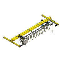
Yale SHAW-BOX Y80 Series Assembly & Instruction Manual (60 pages)
CRANE KIT
Brand:
Yale
| Category:
Construction Equipment
| Size: 47.74 MB
Table of Contents
Table of Contents
2
Safety Precautions
4
Important Information and Warnings
5
Fabrication of Girder(S) for Bridge Beam with Capping Channel
8
Step 1: Cut Girder and C-Channel (as Required)
9
Step 2: Check Camber (as Required)
9
Step 3: Girder and C-Channel Welding at End (as Required)
10
Step 4: Clamping Girder and C-Channel (as Required)
10
Step 5: Girder and C-Channel Welding (as Required)
11
Step 6: Check Camber after Welding (as Required)
11
Assembling Bridge Girder to End Trucks (Single Girder)
12
A) Trsg End Truck Types
13
B) Integral-Axle Tube-Frame End Truck
14
C) Fixed Axle End Truck
15
D) Channel Type End Truck
16
E) Rotating Axle Top Running End Truck
17
Step 1: Notching Girder at Ends (as Required)
18
Step 2: Mounting Girder on Support (as Required)
18
Step 3: Locate & Align End Trucks
19
Step 4: Position End Trucks
19
Step 5: Check Squareness between End Trucks
20
Step 6: Check Span Distance between End Trucks
20
Step 7: Welding End Trucks with Girder
21
Step 8: Tria Metric End Truck Drive Installation
22
Step 8A: Trfa End Truck A4 Drive Installation
23
Step 8B: Trfc End Truck Drive Installation
24
Step 8C: Trra End Truck Drive Installation
25
Step 9: Bridge Bolted Plate End Connection Single Girder
26
End Stops & Trolley Stops
27
A) End Stop Assembly
28
B Trolley Stops Supplied by Customer
28
Mounting Hoist on Girder
29
Yk/Sk Hoist Installation
30
Step 1: Preparation for Mounting Hoist on Girder
30
Step 2: Mounting Hoist on Girder
31
Y80/800 Hoist Installation
32
Step 1: Preparation for Mounting Hoist on Girder
32
Step 2: Mounting Hoist on Girder
33
Festoon System Installation
34
A) Plan View
35
Step 1: Clamping Cross Arm & Control Box Support Rails
36
Step 2: Spacing for Cross Arms/Support Rails
36
Step 3: C-Rail Mounting
37
Step 4: C-Rail Joint Assembly
38
Step 5: Mounting Bridge Panel
39
Step 6: End Stop Assembly
40
Step 7: Hoist Cable Assembly
41
Step 8: Control Pendant Cable Assembly
42
Yk/Sk Tow Arm
43
Step 9: Tow Arm Kit Preparation
43
Tow Arm Adjustments
43
Y80/800 Tow Arm
44
Step 9: Tow Arm Kit Preparation
44
Tow Arm Adjustments
44
Step 10: Tow Arm Kit Installation - Yk/Sk
45
Step 10: Tow Arm Kit Installation - Y80/800
46
Step 11: Cable Tray Installation
47
Step 12: Placing Festoon Cables on Cable Tray
48
Step 13: Festoon Cable Connection
49
Step 14: Push-Button Pendant Assembly
50
Step 15: Bridge Motor Cable Connection
51
Step 16: Bridge Tow Arm Installation
52
Step 17: Bridge Travel Limit Switch Installation
53
Step 18: Festoon Runway Checking
54
Step 19: Adding Cable Ties
54
Radio Control & Horn Installation for Festoon System
55
Step 1: Cross Arm & Bracket Installation for Radio Control
56
Step 2: Radio Control System Installation
57
Step 3: Horn Installation (Internal/External)
58
Warranty
60
Advertisement
Related Products
Yale SHAW-BOX YK Series
Yale SHAW-BOX SK Series
Yale SHAW-BOX 800 Series
Yale Y804B-HD
Yale Y804A-HD
Yale Y804A-HD1080
Yale YDM4109
Yale YLITP
Yale YDM4109 Plus
Yale YDG413A
Yale Categories
Locks
Door locks
Security System
Door Opening System
Chain Hoists
More Yale Manuals
Login
Sign In
OR
Sign in with Facebook
Sign in with Google
Upload manual
Upload from disk
Upload from URL