Sign In
Upload
Manuals
Brands
Wavecom Manuals
Computer Hardware
Integra M2106+
Wavecom Integra M2106+ Manuals
Manuals and User Guides for Wavecom Integra M2106+. We have
1
Wavecom Integra M2106+ manual available for free PDF download: Product Specification
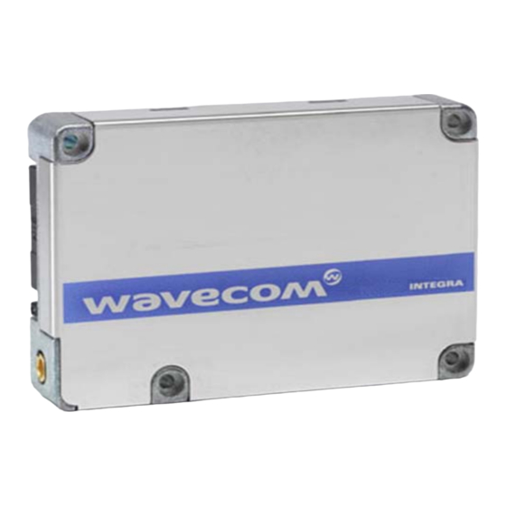
Wavecom Integra M2106+ Product Specification (77 pages)
Plug & Play Wireless CPU
Brand:
Wavecom
| Category:
Computer Hardware
| Size: 1.22 MB
Table of Contents
Web Site Support
4
Table of Contents
6
1 References
10
Reference Documents
10
Open at Software Documentation
10
AT Software Documentation
10
Other Documents
10
Agreement
12
2 General Description
13
Presentation
13
Figure 1: M2106+ View
13
Figure 2: Integra M2106+ Wireless CPU ® Connectors
13
Agreement
13
Key Features
14
Difference between M2106B and M2106+ Wireless CPU
14
Agreement
14
GSM/GPRS Services
15
Agreement
15
Functional Description
16
Block Diagram
16
Figure 3: Functional Architecture
16
Agreement
16
RF Functionalities
17
Firmware
17
CE Conformity
17
Rohs Compliance
17
Agreement
17
3 Interfaces
18
General Purpose Connector
18
Agreement
18
Figure 4: 50-Pin Connector
18
Agreement
19
Figure 5: Pin Allocation
19
Pin Allocation
19
Agreement
20
Signal Description
20
Agreement
21
Power Supply
22
Agreement
22
Agreement
23
ON/~OFF Control
24
General Description
24
Agreement
24
Operating Sequences
25
Agreement
25
Figure 6: Power-ON Sequence Diagram (no PIN Code Activated)
25
Agreement
26
Figure 7: Power-OFF Sequence Diagram
27
Agreement
27
Alternative Download Control (BOOT Pin)
28
Figure 8: BOOT Application Schematic
28
Agreement
28
Reset Signal (~RST)
29
General Presentation
29
Figure 9: Reset Application Schematic
29
Agreement
29
Reset Sequence
30
Figure 10: Reset Sequence Diagram
30
Agreement
30
Serial Link
31
Interface Description
31
Agreement
31
Application Note with Level Shifter
32
SPI Bus
32
Figure 11: Level Shifter Application Diagram for Serial Link
32
Agreement
32
Keyboard Interface
33
Agreement
33
Audio Interface
34
Microphone Inputs
34
Agreement
34
Figure 12: MIC2 Input Connection
35
Agreement
35
Speaker Outputs
36
Figure 13: MIC1 Differential Connection
36
Agreement
36
Figure 14: Speaker Differential Connection
37
Figure 15: Speaker Single-Ended Connection
37
Agreement
37
General Purpose Input/Output
38
Agreement
38
Analog to Digital Converter (ADC)
39
Activity Status Indication (Flashing LED)
39
Agreement
39
Agreement
40
RF Interface
41
RF Interface Characteristics
41
RF Performance
41
Agreement
41
Antenna Specifications
42
Agreement
42
SIM Card Interface
43
Agreement
43
Agreement
44
Figure 16: SIM Card Holder Extraction
44
Internal SIM Card Interface
44
Agreement
45
External SIM Card Interface
45
Agreement
46
Figure 17: Schematic for External SIM Card Holder
46
4 Technical Specifications
47
Environmental Constraints
47
Mechanical Specifications
47
Mechanical Overview
47
Figure 18: Mechanical Overview 1/3
47
Figure 19: Mechanical Overview 2/3
47
Agreement
47
Mechanical Characteristics
48
Mechanical Drawings
48
Agreement
48
Figure 20: Mechanical Overview 3/3
48
Agreement
49
WA_DEV_M2106+_PTS_003-001 April
49
Electrical Specifications
50
Power Mode
50
Agreement
50
Power Consumption Without Open at
51
Processing
51
Agreement
51
Power Consumption with Open at Processing
52
Agreement
52
Current Consumption Waveform
53
Agreement
53
5 Applicable Normative Documents
54
Normative Specifications
54
Agreement
54
Environmental Specifications
55
Agreement
55
Agreement
56
Agreement
57
6 Using the Integra Wireless CPU
58
Firmware Upgrade
58
Nominal Upgrade Procedure
58
Alternative Procedure
58
Guidelines for Application Design
58
Hardware Recommendations
58
Agreement
58
Antenna
59
Minimum Hardware Interface to Get Started
59
Agreement
59
V SIM Management
60
Figure 21: Schematic for a SIM Level Shifter to Manage 5 V SIM Cards
60
Agreement
60
Installation of the Integra M2106+ Wireless CPU
61
On an Application Board
61
Agreement
61
Figure 22: Recommended Footprint
62
Agreement
62
Integra Development Kit Board Presentation
63
Agreement
63
Figure 23: Integra Development Kit Board Description
63
Agreement
64
Getting Started
64
Setting up Terminal Emulator
64
Agreement
65
Example of at Commands
65
Agreement
66
Agreement
67
7 Troubleshooting
68
Not Connecting through the Serial Link
68
Agreement
68
Receiving 'No Carrier' Messages
69
Agreement
69
Agreement
70
Receiving Error Messages
71
Agreement
71
Agreement
72
8 Annexes
73
Supplier Information
73
General Purpose Connector
73
Figure 24: High and Low Profile CLP Connectors
73
Figure 25: Flexible Flat Cable (Part Number: FFSD-20-S-10-01-N)
73
Figure 26: Flex Cable Connector (Part Number: FLE 125 01LDVA)
73
Agreement
73
Antenna Connector
74
SIM Card Holder
74
Figure 27: MMCX Connector Example (Right Angle)
74
Agreement
74
Safety Recommendations (for Information Only)
75
RF Safety
75
Agreement
75
General Safety
76
Agreement
76
Safety Standards
77
Agreement
77
Advertisement
Advertisement
Related Products
Wavecom Fastrack M1206
Wavecom FASTRACK M1306B
Wavecom Fastrack M1200 series
Wavecom Open AT Fastrack M13 Series
Wavecom CM52
Wavecom GR4x
Wavecom GR64 GSM/GPRS
Wavecom Categories
Modem
Test Equipment
Computer Hardware
Software
Transceiver
More Wavecom Manuals
Login
Sign In
OR
Sign in with Facebook
Sign in with Google
Upload manual
Upload from disk
Upload from URL