Sign In
Upload
Manuals
Brands
WAGO Manuals
I/O Systems
753-431
WAGO 753-431 Manuals
Manuals and User Guides for WAGO 753-431. We have
1
WAGO 753-431 manual available for free PDF download: Manual
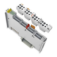
WAGO 753-431 Manual (52 pages)
8DI 24V DC, 0.2ms, 8-Channel Digital Input Module 24 VDC, 1-conductor connection; high-side switching
Brand:
WAGO
| Category:
I/O Systems
| Size: 2.28 MB
Table of Contents
Table of Contents
3
Notes about this Documentation
5
Validity of this Documentation
5
Copyright
5
Symbols
6
Number Notation
8
Font Conventions
8
Table 1: Number Notation
8
Table 2: Font Conventions
8
Important Notes
9
Legal Bases
9
Subject to Changes
9
Personnel Qualifications
9
Use of the WAGO-I/O-SYSTEM 750 in Compliance with Underlying Provisions
9
Technical Condition of Specified Devices
10
Safety Advice (Precautions)
11
Device Description
13
View
15
Figure 1: View
15
Table 3: Legend for Figure "View
15
Connectors
17
Data Contacts/Internal Bus
17
Figure 2: Data Contacts
17
Power Jumper Contacts/Field Supply
18
Figure 3: Power Jumper Contacts
18
Table 4: Legend for Figure "Power Jumper Contacts
18
Cage Clamp
19
Figure 4: CAGE CLAMP ® Connectors
19
Table 5: Legend for Figure "CAGE CLAMP ® Connectors
19
Display Elements
20
Operating Elements
20
Figure 5: Display Elements
20
Table 6: Legend for Figure "Display Elements
20
Schematic Diagram
21
Figure 6: Schematic Diagram
21
Technical Data
22
Device Data
22
Supply
22
Communication
22
Inputs
22
Connection
22
Table 7: Technical Data - Device
22
Table 8: Technical Data - Supply
22
Table 9: Technical Data - Communication
22
Table 10: Technical Data - Inputs
22
Climatic Environmental Conditions
23
Table 14: Technical Data - Climatic Environmental Conditions
23
Approvals
24
Standards and Guidelines
25
Process Image
26
Table 15: Input Bits
26
Mounting
27
Mounting Sequence
27
Inserting and Removing Devices
28
Inserting the I/O Module
28
Figure 7: Insert I/O Module (Example)
28
Figure 8: Snap the I/O Module into Place (Example)
28
Removing the I/O Module
29
Figure 9: Removing the I/O Module (Example)
29
I/O Modules with Pluggable Wiring Level (Series 753)
30
Figure 10: Connector and Module
30
Figure 11: Assignment of Module to Connector Using Mini-WSB Tags
30
Figure 12: Attachment of Cable Binders
30
Coding
31
Figure 13: Assembling the Coding Fingers
31
Figure 14: Inserting the Coding Fingers
31
Figure 15: Plugging the Connector into Place
31
Figure 16: "Sure Match" Coding Fingers
32
Connector Removal
33
Figure 17: Pulling the Pull Tab
33
Figure 18: Removing the Connector Without Tools
33
Figure 19: Removing the Connector Using a Screwdriver
33
Connect Devices
34
Connecting a Conductor to the CAGE CLAMP
34
Figure 20: Connecting a Conductor to a CAGE CLAMP
34
Use in Hazardous Environments
36
Marking Configuration Examples
37
Marking for Europe According to ATEX and IEC-Ex
37
Figure 21: Side Marking Example for Approved I/O Modules According to ATEX and Iecex
37
Figure 22: Text Detail - Marking Example for Approved I/O Modules According to ATEX and Iecex
37
Table 16: Description of Marking Example for Approved I/O Modules According to ATEX and Iecex
38
Table 18: Description of Marking Example for Approved I/O Modules
38
Figure 23: Side Marking Example for Approved Ex I I/O Modules According to ATEX and Iecex
39
Figure 24: Text Detail - Marking Example for Approved Ex I I/O Modules According to ATEX and Iecex
39
Table 17: Description of Marking Example for Approved Ex I I/O Modules According to ATEX and Iecex
41
Marking for America According to NEC 500
42
Figure 25: Side Marking Example for I/O Modules According to NEC 500
42
Figure 26: Text Detail - Marking Example for Approved I/O Modules
42
Installation Regulations
43
Special Conditions for Safe Use (ATEX Certificate TÜV 07 ATEX 554086 X)
44
Special Conditions for Safe Use (ATEX Certificate TÜV 12 ATEX 106032 X)
45
Special Conditions for Safe Use (IEC-Ex Certificate TUN 09.0001 X)
46
Special Conditions for Safe Use (IEC-Ex Certificate Iecex TUN 12.0039 X)
47
Special Conditions for Safe Use According to ANSI/ISA
48
List of Figures
49
List of Tables
50
Advertisement
Advertisement
Related Products
WAGO 753-454
WAGO I/O-SYSTEM 753-456
WAGO 753-452
WAGO 753-461
WAGO 753-461/003-000
WAGO 753-482
WAGO WAGO-I/O-SYSTEM 753-661/000-003
WAGO 753 Series
WAGO 753-540
WAGO 753-506
WAGO Categories
I/O Systems
Control Unit
Power Supply
Switch
Controller
More WAGO Manuals
Login
Sign In
OR
Sign in with Facebook
Sign in with Google
Upload manual
Upload from disk
Upload from URL