Sign In
Upload
Manuals
Brands
Thermo Scientific Manuals
Laboratory Equipment
Mercury Freedom 80i
User Manuals: Thermo Scientific Mercury Freedom 80i Gas
Manuals and User Guides for Thermo Scientific Mercury Freedom 80i Gas. We have
2
Thermo Scientific Mercury Freedom 80i Gas manuals available for free PDF download: Instruction Manual, Manual
Thermo Scientific Mercury Freedom 80i Instruction Manual (333 pages)
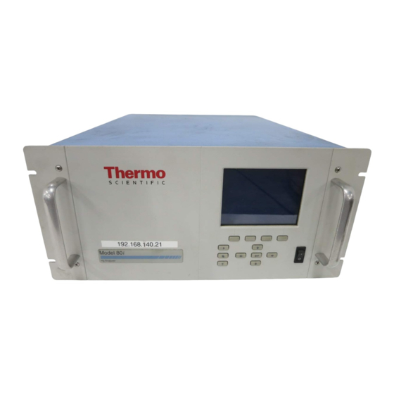
Hg Analyzer
Brand:
Thermo Scientific
| Category:
Measuring Instruments
| Size: 2 MB
Table of Contents
WEEE Compliance
3
About this Manual
5
WEEE Symbol
7
Where to Get Help
7
Table of Contents
9
Introduction
23
Principle of Operation
24
Figure 1-1. Model 80I Flow Schematic
25
Specifications
26
Table 1-1. Model 80I Specifications
26
Installation
27
Lifting
27
Unpacking and Inspection
27
Figure 2-2. Installing the Orifices
29
Setup Procedure
29
Figure 2-3. Connect Glass Orifice for Stand-Alone Configuration
30
Stand-Alone Installation
30
Figure 2-4. Model 80I Rear Panel
31
System Installation
31
Figure 2-5. 80I and 81I Plumbing Connections
32
Connecting External Devices
33
Figure 2-6. Model 80I Bypass Dump Connections
33
25-Pin Terminal Board
34
D/O Terminal Board
34
Figure 2-7. I/O Terminal Board Views
34
I/O Terminal Board
34
Terminal Board PCB Assemblies
34
Figure 2-8. D/O Terminal Board Views
35
Table 2-1. I/O Terminal Board Pin Descriptions
35
Figure 2-9. 25-Pin Terminal Board Views
36
Table 2-2. D/O Terminal Board Pin Descriptions
36
Table 2-3. 25-Pin Terminal Board Pin Descriptions
37
Turn the Power on
37
Operation
39
Display
40
Figure 3-1. Front Panel Display
40
Concentrations
41
Figure 3-2. Front Panel Pushbuttons
41
Pushbuttons
41
Table 3-1. Front Panel Pushbuttons
41
Firmware Overview
42
Soft Keys
42
Figure 3-3. Flowchart of Menu-Driven Firmware
43
Power-Up Screen
44
Run Screen
44
Main Menu
45
Hg , Hg
46
Range Menu
46
Set Custom Ranges
46
Averaging Time
47
Custom Ranges
47
Calibration Factors Menu
48
Hg and Hg Backgrounds
48
Hg , Hg , and Hg Coefficients
49
Dilution Ratio
50
Calibration Menu
51
Reset User Calibration Default
51
Auto Zero/Span Check
52
Next Time
53
Period Hours
53
Instrument/System Zero/Span Calibration Reset
54
Instrument/System Zero/Span Duration Minutes
54
System Hg Span Concentration
55
Zero/Span Averaging Time
55
Gas Mode
56
Instrument Controls Menu
56
Component Power
57
Lamp Supply
57
PMT Supply
58
Probe Power
58
Umbilical 1 and 2 Power
58
Converter Power
59
Eductor Valve Power
59
Stinger Power
59
Auto/Manual Mode
60
Datalogging Settings
60
Select SREC/LREC
61
View Logged Data
61
Date and Time
62
Number of Records
62
Erase Log
63
Select Content
63
Analog Inputs
64
Concentrations
64
Other Measurements
64
Commit Content
65
Configure Datalogging
66
Reset to Default Content
66
Change Value
67
Data Treatment
67
Logging Period Min
67
Memory Allocation Percent
67
Communication Settings
68
Serial Settings
68
TCP/IP Settings
68
Baud Rate
69
Data Bits
69
Parity
69
Stop Bits
69
Instrument ID
70
RS-232/RS-485 Selection
70
Communication Protocol
71
Streaming Data Configuration
71
Analog Inputs
73
Use DHCP
74
IP Address
75
Netmask
75
Default Gateway
76
Host Name
76
I/O Configuration
77
Logic State
77
Output Relay Settings
77
Alarms
78
Instrument State
78
Non-Alarm
78
Digital Input Settings
80
Instrument Action
80
Logic State
80
Analog Output Configuration
81
Allow Over/Under Range
82
Minimum and Maximum Value
83
Select Output Range
83
Table 3-2. Analog Output Zero to Full-Scale Table
83
Choose Signal to Output
84
Table 3-3. Signal Type Group Choices
85
Analog Input Configuration
86
Descriptor
86
Decimal Places
87
Units
87
Number of Table Points
88
User Value
88
Volts
88
Pressure Compensation
89
Temperature Compensation
89
Lamp Compensation
90
Oxygen Quencing Compensation
90
Compensation Mode
91
Dilution O2 Percent
91
Manual O2 Percent
91
Stack O 2 Input Channel (Auto Mode)
91
Alarms Associated with the Oxygen Sensor
92
Compensation Coefficients
92
Next Time
93
Oxidation Schedule
93
Probe Blow Back Schedule
93
Period
94
Solenoid States
94
System/Stinger Duration Seconds
94
Screen Contrast
95
Service Mode
95
Date/Time
96
Timezone
96
Diagnostics Menu
97
Program Versions
97
Interface Board 80I
98
Interface Board 82I
98
Motherboard Voltages
98
Voltages
98
I/O Board Voltages
99
Analyzer
100
Probe
100
Temperatures
100
Analyzer
101
Pressure
101
Probe
101
Drift
102
Flow
102
Lamp Intensity
102
Analog Input Readings
103
Analog Input Voltages
103
Digital Inputs
103
Relay States
104
Test Analog Outputs
104
81I TCPIP
105
>81I CAL ENABLED
105
Set Analog Outputs
105
System Configuration
105
Enhanced Gain
106
Permeation
106
Probe Type
106
Alarms Menu
107
Contact Information
107
Instrument
108
Internal Temperature
109
Min and Max Internal Temperature Limits
109
Chamber Temperature
110
Lamp Temperature
111
Min and Max Lamp Temperature Limits
111
Pressure
111
Min and Max Pressure Limits
112
Intensity
113
Min and Max Flow Limits
113
Min and Max Intensity Limits
113
Zero and Span Auto Calibration
114
Zero/Span/Probe Zero Check
114
Max Zero/Span/Probe Zero Offset
115
Min and Max Probe Dilution Factor Limits
115
Probe Dilution Factor
115
Hg , Hg 2+ , and Hg T Concentration
116
Min Trigger
117
Probe
117
Umbilical Temperature
118
Converter Temperature
119
Min and Max Probe Temperature Limits
119
Min and Max Converter Temperature Limits
120
Oxidizer Temperature
120
Venturi Pressure
121
Dilution Pressure
122
Min and Max Orifice Pressure Limits
122
Blow Back Pressure
123
Eductor Pressure
124
Min and Max Blow Back Pressure Limits
124
Min and Max Eductor Pressure Limits
124
Service Menu
125
Vacuum Pressure
125
PMT Voltage Adjustment
126
Set Temperatures
126
Bench Set Temperature
127
Probe Set Temperature
127
Umbilical Set Temperature
128
Converter Set Temperature
129
Oxidizer Set Temperature
129
Lamp Set Temperature
130
Set Pressures
130
Blow Back Set Pressure
131
Eductor Set Pressure
131
Dilution Set Pressure
132
Pressure Calibration
132
Calibrate Pressure Span
133
Calibrate Pressure Zero
133
Flow Calibration
134
Restore Default Calibration
134
Calibrate Flow Span
135
Calibrate Flow Zero
135
Restore Default Calibration
135
Input Board Calibration
136
Manual Input Calibration
136
Automatic Input Calibration
137
Input Frequency Display
137
Analog Output Calibration
138
Temperature Calibration
138
Analog Output Calibrate Full-Scale
139
Analog Output Calibrate Zero
139
Analog Input Calibration
140
Analog Input Calibrate Zero
141
Display Pixel Test
141
Password
142
Restore User Defaults
142
Lock Instrument
143
Set Password
143
Change Password
144
Remove Password
144
Unlock Instrument
144
Chapter 4 Calibration
145
Equipment Required
145
Zero Gas Generator
145
Drying
145
Scrubbing
146
Pre-Calibration
146
Table 4-1. Scrubbing Materials
146
Calibration
147
Connect 80I to 81I
147
Adjust Instrument Gain
147
Calibrate the Hg Channel to the Hg Calibration Gas
148
Calibrate the Hgt Channel
149
Zero and Span Check
150
Safety Precautions
151
Chapter 5 Preventive Maintenance
151
Replacement Parts
152
Cleaning the Outside Case
152
Visual Inspection and Cleaning
152
Cleaning the Mirror
152
Critical Orifice Inspection and Replacement
152
Figure 5-1. Inspecting and Replacing the Orifices
153
Fan Filter Inspection and Cleaning
154
Lamp Voltage and Frequency Check
155
Leak Test
155
Figure 5-2. Inspecting and Cleaning the Fan
155
Chapter 6 Troubleshooting
157
Safety Precautions
158
Troubleshooting Guides
158
Table 6-1. Troubleshooting - Power-Up Failures
158
Table 6-2. Troubleshooting - Calibration Failures
159
Table 6-3. Troubleshooting - Measurement Failures
161
Table 6-4. Troubleshooting - Alarm Messages
163
Board-Level Connection Diagrams
165
Figure 6-1. Board-Level Connection Diagram
165
Connector Pin Descriptions
166
Table 6-5. Motherboard Connector Pin Descriptions
166
Table 6-6. Measurement Interface Board Connector Pin Descriptions
171
Table 6-7. Front Panel Board Connector Pin Diagram
174
Table 6-8. I/O Expansion Board Connector Pin Descriptions
176
Table 6-9. Digital Output Board Connector Pin Descriptions
177
Table 6-10. Input Board Connector Pin Descriptions
178
Service Locations
179
Chapter 7 Servicing
181
Safety Precautions
182
Figure 7-1. Properly Grounded Antistatic Wrist Strap
183
Firmware Updates
184
Replacement Parts List
184
Table 7-1. Model 80I Replacement Parts
184
Cable List
185
External Device Connection Components
185
Table 7-2. Model 80I Cables
185
Table 7-3. External Device Connection Components
185
Figure 7-2. Model 80I Component Layout
186
Removing the Measurement Bench and Lowering the Partition Panel
187
Figure 7-3. Removing the Measurement Bench and Lowering the Partition Panel
187
Accessing the Service Mode
188
Fuse Replacement
189
External Pump Replacement
189
Fan Replacement
189
Optical Bench Replacement
190
Figure 7-4. Replacing the Fan
190
Figure 7-5. Replacing the Optical Bench
191
Lamp Replacement
192
Figure 7-6. Replacing the Lamp
192
Lamp HVPS Assembly Replacement
193
Lamp Reference Detector Assembly Replacement
193
Photomultiplier Tube Replacement
194
Figure 7-7. Replacing the Reference Detector Assembly
194
Figure 7-8. Replacing the PMT
195
PMT High Voltage Power Supply Replacement
196
PMT Voltage Adjustment
197
Figure 7-9. Replacing the PMT High Voltage Power Supply (HVPS)
197
DC Power Supply Replacement
198
Analog Output Testing
199
Figure 7-10. Replacing the DC Power Supply
199
Figure 7-11. Rear Panel Analog Input and Output Pins
200
Analog Output Calibration
201
Table 7-4. Analog Output Channels and Rear Panel Pin Connections
201
Analog Input Calibration
202
Calibrating the Input Channels to Zero Volts
202
Calibrating the Input Channels to Full Scale
203
Pressure Transducer Assembly Replacement
204
Table 7-5. Analog Input Channels and Rear Panel Pin Connections
204
Figure 7-12. Replacing the Pressure Transducer Assembly
205
Pressure Transducer Calibration
206
Flow Transducer Replacement
207
Flow Transducer Calibration
208
Figure 7-13. Replacing the Flow Transducer
208
Heater Assembly Replacement
210
Thermistor Replacement
211
Figure 7-14. Replacing the Heater Assembly
211
Ambient Temperature Calibration
212
Figure 7-15. Replacing the Thermistor
212
Input Board Replacement
213
Figure 7-16. Replacing the Input Board
214
Input Board Calibration
215
I/O Expansion Board Replacement
215
Figure 7-17. Replacing the I/O Expansion Board (Optional)
216
Digital Output Board Replacement
217
Figure 7-18. Rear Panel Board Connectors
217
Motherboard Replacement
218
Measurement Interface Board Replacement
219
Front Panel Board Replacement
220
Figure 7-19. Replacing the Measurement Interface Board
220
LCD Module Replacement
221
Figure 7-20. Replacing the Front Panel Board and the LCD Module
221
Service Locations
222
Chapter 8 System Description
223
Hardware
223
Optics
224
Fluorescence Chamber
224
Photomultiplier Tube (PMT)
224
Figure 8-1. Hardware Components
224
Input Board
225
Lamp Reference Detector
225
Flow Sensor
225
Pressure Transducer
225
Critical Orifices
225
External Pump
225
Firmware
225
Instrument Control
226
Monitoring Signals
226
Measurement Calculations
226
Output Communication
227
Electronics
227
Motherboard
227
External Connectors
227
Internal Connectors
227
Measurement Interface Board
228
Measurement Interface Board Connectors
228
Flow Sensor Assembly
229
Pressure Sensor Assembly
229
Temperature Control
229
Lamp Power Supply Assembly
229
PMT Power Supply Assembly
229
Input Board
229
Digital Output Board
230
Front Panel Connector Board
230
I/O Expansion Board
230
I/O Components
230
Analog Voltage Outputs
231
Analog Current Outputs
231
Analog Voltage Inputs
231
Digital Output Relays
232
Digital Inputs
232
Serial Ports
232
RS-232 Connection
232
Ethernet Connection
233
Table 8-1. RS-232 DB9 Connector Pin Configurations
233
Table 8-2. RS-485 DB9 Connector Pin Configuration
233
External Accessory Connector
234
Chapter 9 Optional Equipment
235
Terminal Block and Cable Kits
235
25-Pin Terminal Board Assembly
235
Cables
236
Table 9-1. Cable Options
236
Table 9-2. Color Codes for 25-Pin and 37-Pin Cables
236
Mounting Options
237
Table 9-3. Mounting Options
237
Figure 9-1. Rack Mount Option Assembly
238
Figure 9-2. Bench Mounting
239
Figure 9-3. EIA Rack Mounting
240
Figure 9-4. Retrofit Rack Mounting
241
Appendix A Warranty
243
Appendix B C-Link Protocol Commands
245
Instrument Identification Number
246
Commands
246
Accessing Streaming Data
247
Service Mode
247
Table B-1. Command Response Error Descriptions
247
Commands List
248
Table B-2. C-Link Protocol Commands
248
Measurements
256
Table B-3. Averaging Times
256
Figure B-1. Flag Status
258
Alarms
259
Table B-4. Alarm Trigger Values
265
Diagnostics
267
Datalogging
268
Table B-5. Record Output Formats
271
Calibration
275
Table B-6. Stream Time Values
275
Keys/Display
277
Measurement Configuration
279
Lamp Intensity
285
Table B-7. Standard Ranges
285
Pmt Supply
290
Hardware Configuration
293
Table B-8. Contrast Levels
293
Communications Configuration
295
Table B-9. Reply Termination Formats
298
Table B-10. Allow Mode Command Values
300
Table B-11. Power up Mode Command Values
301
Table B-12. Set Layout Ack Values
301
I/O Configuration
302
Table B-13. Analog Current Output Range Values
302
Table B-14. Analog Voltage Output Range Values
303
Table B-15. Default Output Assignment
304
Record Layout Definition
306
Format Specifier for ASCII Responses
307
Format Specifier for Binary Responses
307
Format Specifier for Front-Panel Layout
308
Text
308
Value String
308
Value Source
308
Alarm Information
309
Translation Table
309
Selection Table
309
Button Designator
309
Examples
310
Appendix Cmodbus Protocol
313
Serial Communication Parameters
313
TCP Communication Parameters
314
Application Data Unit Definition
314
Slave Address
314
MBAP Header
314
Function Code
314
Data
314
Error Check
314
Function Codes
315
(0X01/0X02) Read Coils / Read Inputs
315
(0X03/0X04) Read Holding Registers / Read Input Registers
317
(0X05) Force (Write) Single Coil
319
MODBUS Addresses Supported
320
Table C-1. Read Coils for 80I
320
Table C-2. Read Registers for 80I
323
Table C-3. Write Coils for 80I
325
Index
327
Advertisement
Thermo Scientific Mercury Freedom 80i Manual (104 pages)
Brand:
Thermo Scientific
| Category:
Laboratory Equipment
| Size: 3 MB
Table of Contents
Table of Contents
7
Chapter 1 Introduction
15
System Overview
15
Model 80I
15
Model 81I
16
Figure 1-1. Model 80I Flow Diagram
16
Table 1-1. Model 81I Valve Mode Status
17
Model 82I
18
Figure 1-2. Model 81I Flow Diagram
18
Pneumatics
19
Electronics
19
Figure 1-3. Model 82I Probe Controller Flow Diagram
19
Electrical Power
20
Model 83I
20
Figure 1-4. Model 83I Probe Flow Diagram
22
Figure 1-5. Model 83I Probe Flow Diagram with Oxidizer
23
Model 83I GC
24
Mercuric Chloride Generator
25
Component Description
25
Oxidizer Weldment
25
Heater
25
Figure 1-6. Oxidizer Flow Diagram
25
Heater Block
26
Thermocouple
26
Insulation
26
Oxidizer Enclosure
26
Figure 1-7. Oxidizer Components
26
Hydrator
27
Figure 1-8. Hydrator System Mount and Close-Up View
27
Figure 1-9. Hydrator Components
27
Nitrogen Generator
28
Zero Air Supply
28
Figure 1-10. Zero Air Panel System with Nitrogen
28
Scrubber Assembly
29
Stack Mounting Flange
29
Figure 1-11. Scrubber Assembly
29
Umbilical Cable
30
Mercury System Instruction Manuals
30
Figure 1-12. Stack Mounting Flange
30
Chapter 2 System Installation, Set up and Shut down
31
Lifting
31
Hg CEMS Requirements
31
Plumbing and Electrical Hookup
32
Set Temperature Defaults
32
Mercury CEMS Power-Up Sequence
32
Table 2-1. Default Temperatures
32
Start-Up
33
System Checkout
34
Recommended Initial Parameter Settings
36
Initial Service Settings
36
Set-Up Blowback Schedule
36
Table 2-2. Initial Service Settings
36
Table 2-3. Set-Up Blowback Schedule
36
Alarms Settings
37
Probe Alarms Settings
37
Table 2-4. 80I Alarms Settings
37
Table 2-5. Probe Alarms Settings
37
Normal Operational Parameters (with 83I)
38
Table 2-6. Normal Operational Parameters - 83I
39
Normal Operational Parameters (with 83I GC)
40
Nitrogen Generator Venting
40
Shut down the System (Prior to Removal)
40
Table 2-7. Normal Operational Parameters - 83I GC
40
Updating Firmware
41
Chapter 3 Calibration
43
Manual System Calibration
43
Auto System Calibration
45
Table 3-1. Example of Parameter Settings
45
Calibration Check Procedures
46
Zero / Span Check Set-Up
46
Table 3-2. Zero/Span Check Set up
46
Chapter 4 Troubleshooting
47
Safety Precautions
47
System Troubleshooting Guides
47
Before Calling for Service Support
47
Most Common Service Calls
48
Table 4-1. Troubleshooting - most Common Service Calls
48
Power-Up Failures
49
Table 4-2. Troubleshooting - Power-Up Failures
49
Alarm Messages
50
Table 4-3. Troubleshooting - Alarm Messages
50
System Zero and Calibration Troubleshooting
53
Table 4-4. Troubleshooting - System Zero and Calibration
53
Establishing Communication between Instruments in the Mercury System
57
Cabling Instruments in the Mercury System
57
Direct Connection
57
Hub/Router Connection
58
Firmware and Communications Troubleshooting
58
Table 4-5. Troubleshooting - Firmware and Communications
58
Troubleshooting Interface Board Voltages
59
Figure 4-1. Example of Model 80I Interface Board Voltage Test Point Locations
61
Table 4-6. Probe Troubleshooting - 82I Measurement Interface Board Leds
61
Oxidizer Troubleshooting
62
Table 4-7. Communication and 24 V Troubleshooting - 82I Interface Board Leds
62
Table 4-8. Troubleshooting - Oxidizer
62
Troubleshooting - Miscellaneous
64
Table 4-9. Troubleshooting - Miscellaneous
64
Service Locations
65
Chapter 5 Preventive Maintenance
68
System Preventive Maintenance
68
Heated Umbilical
68
Table 5-1. Preventive Maintenance Schedule
68
Heated Umbilical Maintenance
69
Service Locations
70
Chapter 6 Optional Equipment
71
Mercuric Chloride Generator
71
Hydrator
71
Hydrator Installation
71
System Preparation
71
Equipment Installation on Rack Exterior
72
Figure 6-1. Hydrator Mounted Outside Rack
72
Equipment Installation on Rack Interior
73
Retrofit Instructions for Fielded Mercury Systems
73
Figure 6-2. Hydrator Mounted Inside Rack
73
Electrical Connections
74
Figure 6-3. Hydrator Electrical Pinout Diagram
74
Pneumatic Connections
75
Input/Output Configuration
75
Functional Check
76
Zero Air Supply
77
Nitrogen Generator
77
Specifications
77
Table 6-1. Nitrogen Generator Specifications
77
Sources of Compressed Air
80
Generator Performance
80
Recommended Configuration
80
Retrofitting Older Systems
80
A Ppendix a Warranty
81
A Ppendix B System Reference Drawings
83
Figure B-1. 83I System Plumbing Diagram 103013-00
83
Figure B-3. 83I Electrical and Plumbing Installation 103535-00
83
Figure B-4. Wiring Interconnection with 83I GC
83
Figure B-5. 83I with Oxidizer Electrical and Plumbing Installation 103535-01
83
Figure B-6. Tubing Interconnection with 83I GC
83
Figure B-7. 83I GC Plumbing System Diagram 104358-00
83
Figure B-8. 83I GC with Oxidizer Plumbing System Diagram 104358-01
83
Figure B-10. 83I Terminal Block Wiring Diagram 104588-00
83
Figure B-11. 83I GC with Oxidizer Terminal Block Wiring Diagram 104734-00
83
Figure B-2. 83I with Oxidizer System Plumbing Diagram 103013-01
85
Figure B-9. Interconnection Schematic
92
A Ppendix C Flowcharts of Menu-Driven Firmware
97
Figure C-1. Model 80I Flowchart of Menu-Driven Firmware
98
Figure C-2. Model 81I Flowchart of Menu-Driven Firmware
99
Index
101
Advertisement
Related Products
Thermo Scientific 88882002
Thermo Scientific 8141
Thermo Scientific 8146
Thermo Scientific 8238
Thermo Scientific 88881-004
Thermo Scientific 88870006
Thermo Scientific 8926
Thermo Scientific 8927
Thermo Scientific Heraeus Megafuge 8R
Thermo Scientific 899928
Thermo Scientific Categories
Laboratory Equipment
Measuring Instruments
Freezer
Accessories
Refrigerator
More Thermo Scientific Manuals
Login
Sign In
OR
Sign in with Facebook
Sign in with Google
Upload manual
Upload from disk
Upload from URL