Sign In
Upload
Manuals
Brands
Texas Instruments Manuals
Control Unit
ADC DJ 00RF Series
Texas Instruments ADC DJ 00RF Series Manuals
Manuals and User Guides for Texas Instruments ADC DJ 00RF Series. We have
2
Texas Instruments ADC DJ 00RF Series manuals available for free PDF download: User Manual
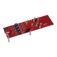
Texas Instruments ADC DJ 00RF Series User Manual (33 pages)
Evaluation Module
Brand:
Texas Instruments
| Category:
Motherboard
| Size: 2 MB
Table of Contents
Figure 1-1. EVM Orientation
2
Table of Contents
3
Trademarks
3
Equipment
4
Figure 2-1. EVM Feature Locations
4
Setup Procedure
6
Figure 3-1. EVM Test Setup
6
Figure 3-2. Configuration GUI EVM Tab
9
Figure 3-3. Configuration GUI ADC Control
10
Figure 3-4. High Speed Data Converter Pro (HSDC) GUI
12
Figure 3-5. Additional Device Parameters Dialog Box
13
Device Configuration
14
Table 4-1. Supported and Non-Supported Features of the JESD204C Device
14
Figure 4-1. Low-Level Register Control Tab
15
Table 4-2. Low-Level Controls
15
Troubleshooting the ADC12DJ5200RFEVM/SEEVM
16
Table 5-1. Troubleshooting
16
References
17
HSDC Pro Settings for Optional ADC Device Configuration
18
Figure 7-1. ADC12DJ5200RFEVM/SEEVM Clocking System Block Diagram
19
Figure 7-2. Onboard Clocking System Block Diagram
20
Figure 7-3. External Reference Clocking System Block Diagram
21
Figure 7-4. External Clock Configuration
22
Figure 7-5. Onboard Clocking Configuration
23
Signal Routing
24
Table 8-1. Adcxxdjxx00Rfevm/Seevm Signal Routing
24
A Analog Inputs
25
Figure A-1. Analog Input Path
25
Table A-1. Analog Input Path
25
Figure A-2. 3 Db Attenuation Pad
26
B Jumpers and Leds
27
B Revision History
27
Table 10-1. Jumper Settings
27
Table 10-2. Leds
27
Advertisement
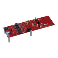
Texas Instruments ADC DJ 00RF Series User Manual (32 pages)
Evaluation Module
Brand:
Texas Instruments
| Category:
Control Unit
| Size: 2 MB
Table of Contents
Figure 1-1. EVM Orientation
2
Table of Contents
3
Trademarks
3
Equipment
4
Figure 2-1. EVM Feature Locations
4
Setup Procedure
6
Figure 3-1. EVM Test Setup
6
Figure 3-2. Configuration GUI EVM Tab
8
Figure 3-3. Configuration GUI ADC Control
9
Figure 3-4. High Speed Data Converter Pro (HSDC) GUI
11
Figure 3-5. Additional Device Parameters Dialog Box
12
Device Configuration
13
Table 4-1. Supported and Non-Supported Features of the JESD204C Device
13
Figure 4-1. Low-Level Register Control Tab
14
Table 4-2. Low-Level Controls
14
Troubleshooting the ADC12DJ5200RFEVM
15
Table 5-1. Troubleshooting
15
References
16
HSDC Pro Settings for Optional ADC Device Configuration
17
Figure 7-1. ADC12DJ5200RFEVM Clocking System Block
18
Figure 7-2. Onboard Clocking System Block Diagram
19
Figure 7-3. External Reference Clocking System Block Diagram
20
Figure 7-4. External Clock Configuration
21
Figure 7-5. Onboard Clocking Configuration
22
Signal Routing
23
Table 8-1. Adcxxdjxx00Rfevm Signal Routing
23
A Analog Inputs
24
Figure A-1. Analog Input Path
24
Table A-1. Analog Input Path
24
Figure A-2. 3 Db Attenuation Pad
25
B Jumpers and Leds
26
B Revision History
26
Table 10-1. Jumper Settings
26
Table 10-2. Leds
26
Advertisement
Related Products
Texas Instruments DAC5571
Texas Instruments DAC8742H
Texas Instruments DAC38RF80EVM
Texas Instruments DAC38RF87EVM
Texas Instruments DRV8803
Texas Instruments DAC7731
Texas Instruments DRV10964
Texas Instruments DAC8811
Texas Instruments DAC8811EVM
Texas Instruments DLP DLPC4420AEVM
Texas Instruments Categories
Motherboard
Control Unit
Microcontrollers
Computer Hardware
Calculator
More Texas Instruments Manuals
Login
Sign In
OR
Sign in with Facebook
Sign in with Google
Upload manual
Upload from disk
Upload from URL