Sign In
Upload
Manuals
Brands
Tektronix Manuals
Inverter
AWG7000 Series
Tektronix AWG7000 Series Manuals
Manuals and User Guides for Tektronix AWG7000 Series. We have
6
Tektronix AWG7000 Series manuals available for free PDF download: Programmer's Manual, Service Manual, Quick Start Manual, Quick Start User Manual, Technical Reference, Manual
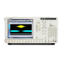
Tektronix AWG7000 Series Programmer's Manual (181 pages)
Arbitrary Waveform Generators
Brand:
Tektronix
| Category:
Inverter
| Size: 2 MB
Table of Contents
Table of Contents
5
Getting Started
9
Introduction
11
Remote Control
12
GPIB Parameters
13
LAN Parameters
14
Connecting to the Instrument Using GPIB
15
Setting up GPIB Communication
16
Documentation
19
Sample Program
20
Syntax and Commands
21
Command Syntax
23
Syntax Overview
23
Command and Query Structure
23
Clearing the Instrument
25
Command Entry
25
Parameter Types
27
SCPI Commands and Queries
31
Command Groups
33
Control Group Commands
33
Calibration Group Commands
34
Diagnostic Group Commands
34
Display Group Commands
36
Event Group Commands
36
Instrument Group Commands
36
Mass Memory Group Commands
36
Output Group Commands
37
Sequence Group Commands
38
Source Group Commands
39
Status Group Command
41
Subsequence Group Commands
42
Synchronization Group Commands
42
System Group Commands
43
Trigger Group Commands
43
Waveform Group Commands
44
Command Descriptions
47
Status and Event Reporting
143
Registers
144
Status Registers
145
Standard Event Status Register (SESR)
146
Operation Enable Register (OENR)
147
Event Status Enable Register (ESER)
148
Questionable Enable Register (QENR)
149
Operation Status Block
150
Standard/Event Status Block
151
Synchronizing Execution
152
Messages and Codes
153
Command Errors
154
Execution Errors
155
Device-SpecifiC Errors
156
Query Errors
157
User Request Event
158
Appendix A: Character Charts
161
Appendix B: GPIB Interface Specifications
163
Appendix B: Gpibinterface Specifications
165
Interface Messages
165
Appendix C: SCPI Conformance Information
167
Appendix D: Raw Socket Specification
171
Appendix E: Factory Initialization Settings
173
Appendix F: Compatibility with Other Instruments
175
Advertisement
Tektronix AWG7000 Series Service Manual (140 pages)
Arbitrary Waveform Generators
Brand:
Tektronix
| Category:
Portable Generator
| Size: 14 MB
Table of Contents
Table of Contents
7
Modules (Top)
17
Table 1-1: General Features
21
Figure 2-1: AWG7000 Series Block Diagram
26
Table 3-1: Test Equipment
34
Figure 3-1: Service UI Menu
35
Figure 3-2: 10 Mhz Reference Calibration Initial Test Hookup
37
Figure 3-3: 10 Mhz Reference Calibration Setup Window
38
Figure 3-4: Data Timing Calibration Initial Hookup
39
Figure 3-5: Data Timing Calibration Setup Window
40
Figure 3-6: Inter-Channel Skew Calibration Initial Hookup
44
Figure 3-7: Inter-Channel Skew Calibration Setup Window
45
Figure 3-8: Interleave Calibration Initial Hookup
48
Figure 3-9: Interleave Calibration Setup Window
49
Table 4-1: External Inspection Checklist
55
Table 4-2: Internal Inspection Checklist
57
Figure 4-1: Disassembly Procedures for External Modules and Internal
60
Figure 4-2: Disassembly Procedures for Internal Modules (Bottom)
61
Figure 4-3: Disconnecting and Connecting the SMP Cable
62
Table 4-3: Tools Required for Module Removal and Reinstall
62
Figure 4-4: Handle, Snaps, Cosmetic Covers, and Front-Trim Unit
64
Figure 4-5: EMI Covers Removal
66
Figure 4-6: Fan Tray Unit Removal
68
Figure 4-7: Disassembly of Front-Panel Assembly
69
Figure 4-8: Drive Module Removal
71
Figure 4-9: Multi-Input/Output Board Removal
73
Figure 4-10: Processor Module Removal
75
Figure 4-11: Power Supply and RFI Filter Removal
77
Figure 4-12: Power Board Removal
78
Figure 4-13: Front Connector Board, CLK10G Module, Relay Unit
80
Figure 4-14: Disassembly of the CLK10G Module
82
Figure 4-17: OUT10G Board Showing the Test Points
90
Figure 4-18: Primary Troubleshooting Tree (1)
92
Figure 4-19: Primary Troubleshooting Tree (2)
93
Figure 4-20: PWR Board Test Points
94
Table 4-4: Power Supply Voltages
94
Figure 4-21: AWG10G Board Test Points
95
Table 4-5: PWR Board Voltages
95
Figure 4-22: Diagnostics Dialog Box
96
Table 4-6: Diagnostics Error
97
Figure 4-23: Calibration Dialog Box
101
Table 4-7: Calibration Error
102
Table 4-8: Hardware Error
105
Figure 5-1: Exploded Diagram - Cosmetics
115
Figure 5-2: Exploded Diagram - EMI Covers
116
Figure 5-3: Exploded Diagram - Chassies Assembly
117
Figure 5-4: Exploded Diagram - Front-Panel Assembly
119
Figure 5-5: Exploded Diagram - Drive Module
121
Figure 5-6: Exploded Diagram - Processor Module
123
Figure 5-7: Exploded Diagram - Power Supply Assembly
125
Figure 5-8: Exploded Diagram - Pci/Power Interface Module
127
Figure 5-9: Exploded Diagram - Fan Tray Assembly
128
Figure 5-10: Exploded Diagram - USB Module
129
Figure 5-11: Exploded Diagram - AWG10G/CLK10G/OUT10G
131
Figure 5-12: Exploded Diagram - CLK10G Module
133
Figure 5-13: Exploded Diagram - AWG10G Module
135
Figure 5-14: Exploded Diagram - SMA Bracket
137
Figure 5-15: Exploded Diagram - Relay Unit
139
Figure 5-16: Exploded Diagram - Rear Connectors
140
Tektronix AWG7000 Series Quick Start Manual (104 pages)
AWG5000 Series and AWG7000 Series Arbitrary Waveform Generators
Brand:
Tektronix
| Category:
Portable Generator
| Size: 7 MB
Table of Contents
Table of Contents
8
General Safety Summary
10
Compliance Information
12
EMC Compliance
12
Safety Compliance
13
Environmental Considerations
14
Preface
15
Key Features
15
Documentation
17
Conventions Used in this Manual
17
Installing Your Instrument
18
Standard Accessories
18
Operating Requirements
19
Powering on the Instrument
20
Powering off the Instrument
21
Windows Interface Guidelines
21
Connecting to a Network
22
Setting GPIB/LAN
22
Controlling the Instrument Using a Remote PC
23
Offline Mode
23
Inspecting Your Instrument
24
Self Calibration
25
Preventing Instrument Damage
26
Option Installation
27
Creating Operating System Restore Discs
28
Creating Restore Discs
28
Restoring the Instrument Operating System
28
Front Panel
30
Rear Panel (AWG7000C Series)
31
Dynamic Jump in Connector (AWG7000C Series)
32
Rear Panel (AWG5000C Series)
33
Getting Acquainted with Your Instrument
35
Control Panel
35
Locking and Unlocking the Front Panel Controls
36
Touch Screen Interface
37
Elo Touchscreen Application
37
Screen Interface
38
Basic Steps for Using the Arbitrary Waveform Generator
39
Run Mode
40
Accessing Menus and Control Windows
41
Changing Control Settings
42
Display/Hide Control Windows
43
Status Bar
44
Setting the User Preferences
45
Changing the Windows Display Style
46
Run State Control and Output On/Off
47
Setting Output Signals
49
Interleave
53
Digital Output (Option 03)
56
Saving and Recalling Setups
57
File Menu
57
Saving an Instrument Setup
58
Recalling an Instrument Setup
59
Default Setup
60
Changing Settings at Power-On
60
Importing Waveform Data
61
Exporting Waveform Data
65
Waveform Display and Edit
67
Waveform Window
67
Using Zoom
68
Creating or Modifying a Waveform
69
Creating a Standard Waveform
70
Equation Editor
72
Accessing Waveform in a Setup File
73
Changing a User-Defined Waveform Name
74
Confirming Waveform Properties
74
Editing a Waveform
75
Math Waveforms
78
Normalize Option
79
Using Other Edit Menu Commands
79
Sequence
85
Sequence Window
85
Creating a Sequence
87
Creating a Subsequence
89
Editing a Sequence
91
Event Jump
93
Force Jump to
94
Accessing Sequence Elements Outside the Display Area
95
Tutorials
96
Creating and Editing a Waveform
96
Creating and Editing a Sequence
98
Index
102
Advertisement
Tektronix AWG7000 Series Quick Start User Manual (90 pages)
Arbitrary Waveform Generators
Brand:
Tektronix
| Category:
Portable Generator
| Size: 10 MB
Table of Contents
Table of Contents
5
General Safety Summary
7
Environmental Considerations
9
Preface
11
Key Features
11
Documentation
12
Conventions Used in this Manual
12
Install Your Instrument
13
Standard Accessories
13
Operating Requirements
14
Powering on the Instrument
15
Powering off the Instrument
15
Windows Interface Guidelines
16
Connecting to a Network
17
Controlling the Instrument Using a Remote PC
17
Offline Mode
18
Inspect Your Instrument
19
Self Calibration
20
Preventing Instrument Damage
21
Accessing Online Help
22
Front Panel
23
Rear Panel
24
Control Panel
25
To Lock/Unlock the Front Panel Controls
27
Touch Screen Interface
27
Changing Control Settings
28
Run State Control and Output On/Off
29
Interface and Display
30
Screen Interface
30
Basic Steps for Using the Arbitrary Waveform Generator
31
Accessing Menus and Control Windows
32
Display/Hide Control Windows
33
Status Bar
34
Waveform List Window
35
Sequence Window
36
Waveform Window
37
Settings Window
38
Default Setup
44
Instrument Settings at Power-On
44
Using the File Menu
45
Saving an Instrument Setup
46
Recalling an Instrument Setup
47
Importing Waveform Data
48
Exporting Waveform Data
52
Using the Edit Menu
53
Creating a Standard Waveform
54
Using Cut, Copy, Paste and Delete (Waveform Window)
56
Defining a Sequence
58
Editing a Sequence
60
Using Set Waveform and Insert Waveform
61
Using Paste-Insert and Paste-Replace
62
Using Rename
63
Using Other Edit Menu Commands
63
Using the View Menu
69
Using Go to Dialog Box
70
Using Display Properties Dialog Box
71
Using Zoom
73
Using the Settings Menu
74
Channel Coupling
75
Using the Tools Menu
76
Math Waveforms
76
Normalize Option
77
Using the System Menu
78
Channel Skew Adjustment
78
Using Force Jump to Dialog Box
79
Setting GPIB/LAN
80
Setting the User Preferences
81
Option Installation
82
Tutorials
83
Creating and Editing a Standard Waveform
83
Editing a Sequence
85
Index
87
Tektronix AWG7000 Series Technical Reference (76 pages)
Arbitrary waveform generators
Brand:
Tektronix
| Category:
Portable Generator
| Size: 1 MB
Table of Contents
Table of Contents
5
Performance Conditions
17
Table 1-1: Run Mode
18
Table 1-2: Arbitrary Waveform
18
Electrical Specifications
18
Table 1-3: Clock Generator
19
Table 1-4: Trigger Generator
19
Table 1-5: Inter-Channel Skew Control (2 Channels Model Only)
19
Table 1-6: Analog Output (Standard)
20
Table 1-7: Analog Output (Option 02 and Option 06)
22
Table 1-8: Interleave Analog Output (AWG7102 Option 06)
23
Table 1-9: Marker Output
24
Table 1-10: Trigger and Gate Input
24
Table 1-11: Event Input
25
Table 1-12: Reference Clock Input
26
Table 1-13: Oscillator (External Clock) Input
26
Table 1-14: DC Output
26
Table 1-15: 10 Mhz Clock Output
27
Table 1-16: Teklink Port
27
Table 1-17: CPU Module and Peripheral Devices
27
Table 1-18: Display
28
Table 1-19: Power Supply
28
Table 1-20: Mechanical Characteristics
28
Table 1-21: Environmental Characteristics
29
Table 1-22: Certifications and Compliances
30
Brief Procedures
37
Figure 2-1: Diagnostics Dialog Box
38
Calibration
38
Figure 2-2: Calibration Dialog Box
39
Functional Test
39
Figure 2-3: Equipment Connections for Checking the Analog and Marker Outputs
40
Figure 2-4: Output Waveform from the Analog, Mkr1, and Mkr 2 Connectors
42
Performance Tests
43
Table 2-1: Equipment Required
43
Table 2-2: Test Waveforms
44
Test Record
45
Figure 2-5: Equipment Connection for Verifying the 10 Mhz Reference Frequency Accuracy
54
Figure 2-6: Equipment Connection for Measuring the Terminator Resistance
55
Analog Offset Accuracy
55
Figure 2-7: Equipment Connection for Verifying the Analog Offset Accuracy
56
Table 2-3: Analog Offset Accuracy
57
Analog Amplitude Accuracy
58
Table 2-4: Analog Amplitude Accuracy
59
Analog Harmonic Distortion
60
Figure 2-8: Equipment Connections for Verifying the Analog
61
Table 2-5: Analog Harmonic Distortion
62
Figure 2-9: Equipment Connections for Verifying the Non-Harmonic Spurious Signal
63
Table 2-6: Analog Non-Harmonic Spurious Signal
64
Analog Phase Noise
65
Figure 2-10: Equipment Connections for Verifying the Analog Phase Noise
66
Figure 2-11: Example of the Analog Phase Noise Measurement
67
Table 2-7: Analog Phase Noise
67
Figure 2-12: Equipment Connection for Verifying the Marker High and Low Level Accuracy
68
Table 2-8: Marker High and Low Level Accuracy
69
Marker Output Delay Accuracy
71
Figure 2-13: Equipment Connections for Verifying the Marker Output Delay Accuracy
72
DC Output Voltage Accuracy
74
Figure 2-14: Equipment Connection for Verifying the DC Output
74
Table 2-9: DC Output Voltage Accuracy
75
Tektronix AWG7000 Series Manual (9 pages)
Arbitrary Waveform Generators
Brand:
Tektronix
| Category:
Portable Generator
| Size: 0 MB
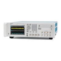
Table of Contents
Contacting Tektronix
2
AWG5000 and AWG7000 Series Product Software
3
Table 1: Product Software CD-ROM Contents
4
Installing the AWG Software
5
Installing the Adobe Reader Software
7
Installing the Tekvisa Software
8
Advertisement
Related Products
Tektronix AWG710
Tektronix AWG710B
Tektronix AWG70002A
Tektronix AWG70001A
Tektronix AWG5000 Series
Tektronix AWG5200 Series
Tektronix AFG3021B
Tektronix AFG3022B
Tektronix AFG3252C
Tektronix AFG31021
Tektronix Categories
Test Equipment
Measuring Instruments
Amplifier
Portable Generator
Printer
More Tektronix Manuals
Login
Sign In
OR
Sign in with Facebook
Sign in with Google
Upload manual
Upload from disk
Upload from URL