Sign In
Upload
Manuals
Brands
SEW-Eurodrive Manuals
DC Drives
MMF31S02-D11-5D3-SFCO0-C/DSP/DFC20A-0020
SEW-Eurodrive MMF31S02-D11-5D3-SFCO0-C/DSP/DFC20A-0020 Manuals
Manuals and User Guides for SEW-Eurodrive MMF31S02-D11-5D3-SFCO0-C/DSP/DFC20A-0020. We have
1
SEW-Eurodrive MMF31S02-D11-5D3-SFCO0-C/DSP/DFC20A-0020 manual available for free PDF download: Operating Instructions Manual
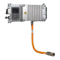
SEW-Eurodrive MMF31S02-D11-5D3-SFCO0-C/DSP/DFC20A-0020 Operating Instructions Manual (368 pages)
Decentralized Frequency Inverter
Brand:
SEW-Eurodrive
| Category:
DC Drives
| Size: 31 MB
Table of Contents
Table of Contents
3
1 General Information
6
About this Documentation
6
Other Applicable Documentation
6
Structure of the Safety Notes
6
Decimal Separator in Numerical Values
7
Rights to Claim under Limited Warranty
7
Product Names and Trademarks
8
Copyright Notice
8
2 Safety Notes
9
Preliminary Information
9
Duties of the User
9
Target Group
10
Designated Use
10
Functional Safety Technology
11
Transportation
11
Installation/Assembly
12
Protective Separation
12
Electrical Installation
12
Startup/Operation
13
3 Device Structure
14
MOVIMOT ® Flexible MMF1
14
MOVIMOT ® Flexible MMF3
15
Cable Entry Position
16
Nameplate Position
17
Example Nameplate and Type Designation
18
Examples for the Optional Nameplate "Plug Connector Positions
21
Electronics
23
Example Nameplate and Type Designation of the Electronics
26
Example Nameplate and Type Designation of Connection Unit
28
4 Mechanical Installation
29
Installation Notes
29
Required Tools and Resources
30
Tolerances for Torque Ratings
30
Installation Requirements
30
Installing the Device
31
Mounting the Unit
36
Mounting the Device with Spacers
38
Tightening Torques
40
5 Electrical Installation
44
Installation Planning Taking EMC Aspects into Account
44
Equipotential Bonding at the Connection Box
48
Installation Instructions
49
Installation Topology (Example: Standard Installation)
57
Terminal Assignment
58
Bulk Cables
61
Connection Diagram
66
Cable Routing and Cable Shielding
68
EMC Cable Glands
73
Plug Connectors
74
Assignment of the Optional Plug Connectors
88
Plug Connector Assignment at the Electronics Cover
123
PC Connection
124
6 Startup
133
Startup Notes
133
Startup Requirements
136
Parameterization Mode
137
Control Elements
138
DIP Switch
142
Detailed Motor Selection Table for Startup Via DIP Switch S3
149
Startup Procedure
156
Startup with the CBG21A Keypad
158
Startup with the CBG11A Keypad
160
Configuring the Digital Inputs/Outputs
162
Setpoint Scaling of the Analog Input
163
Disabling Dynastop for Startup Purposes
164
Configuring the Drive Behavior at Standstill (FCB02, FCB13, FCB14)
166
7 Operation
167
Switch Disconnector
167
Binary Control
168
Manual Mode with MOVISUITE
177
Drive Unit Behavior in Case of a Voltage Failure
180
Dynastop
181
Function "Releasing the Brake / Deactivating Dynastop with FCB01
182
Dynastop® in Conjunction with STO
184
Mechanical Brake in Connection with STO
189
8 Service
190
Evaluating Fault Messages
190
Switch-Off Responses
191
Fault Messages with Parameterizable Response
192
Resetting Fault Messages
195
Description of Status and Operating Displays
195
Fault/Error Table
199
Device Replacement
255
SEW-EURODRIVE Service
259
Shutdown
259
Storage
259
Extended Storage
260
9 Inspection and Maintenance
263
Determining the Operating Hours
263
Inspection and Maintenance Intervals
263
Inspection and Maintenance Work
265
10 Project Planning
270
Preliminary Information
270
SEW-Workbench
270
Schematic Workflow for Project Planning
270
Drive Selection
272
Recommendations for Motor and Inverter Selection
272
Motor/Inverter Assignments
277
Selecting an Inverter
293
Selecting the Braking Resistor
296
11 Technical Data and Dimension Sheets
302
Conformity
302
General Information
303
Technical Data
303
Brake Control
313
Braking Resistors
314
Mounting Kit for Braking Resistor BW
321
Line Choke
325
Screw Fittings
327
Connection Cables
329
11.10 Mounting Positions
331
11.11 Device Dimension Drawings
332
11.12 Dimension Drawings of Plug Connectors in the Electronics Cover
336
11.13 Dimension Drawings of Plug Connectors in the Connection Box
337
11.14 Spacer Dimension Drawings
341
12 Functional Safety
343
General Information
343
Integrated Safety Technology
344
Safety Conditions
349
Connections Variants
354
Safety Characteristics
358
Index
359
Advertisement
Advertisement
Related Products
SEW-Eurodrive MOVIMOT flexible MMF1 C/DBC Series
SEW-Eurodrive MOVIMOT flexible MMF3 C/DBC Series
Sew Eurodrive Movimot MM03D Series
SEW-Eurodrive MOVIMOT MM3D Series
SEW-Eurodrive MOVIMOT MM03C Series
SEW-Eurodrive MOVIMOT MM15C Series
SEW-Eurodrive MOVIMOT MM22C Series
SEW-Eurodrive MOVIMOT MM 03C-503-30
SEW-Eurodrive MOVIMOT MM 05C-503-30
SEW-Eurodrive MOVIMOT MM 11C-503-30
SEW-Eurodrive Categories
Industrial Equipment
DC Drives
Controller
Inverter
Engine
More SEW-Eurodrive Manuals
Login
Sign In
OR
Sign in with Facebook
Sign in with Google
Upload manual
Upload from disk
Upload from URL