Sign In
Upload
Manuals
Brands
Princeton Instruments Manuals
Security System
Activity Tracker
Princeton Instruments Activity Tracker Manuals
Manuals and User Guides for Princeton Instruments Activity Tracker. We have
1
Princeton Instruments Activity Tracker manual available for free PDF download: User Manual
Princeton Instruments Activity Tracker User Manual (168 pages)
Brand:
Princeton Instruments
| Category:
Security System
| Size: 2 MB
Table of Contents
Table of Contents
3
Chapter 1 Introduction
9
Introduction
9
Micromax System Components
9
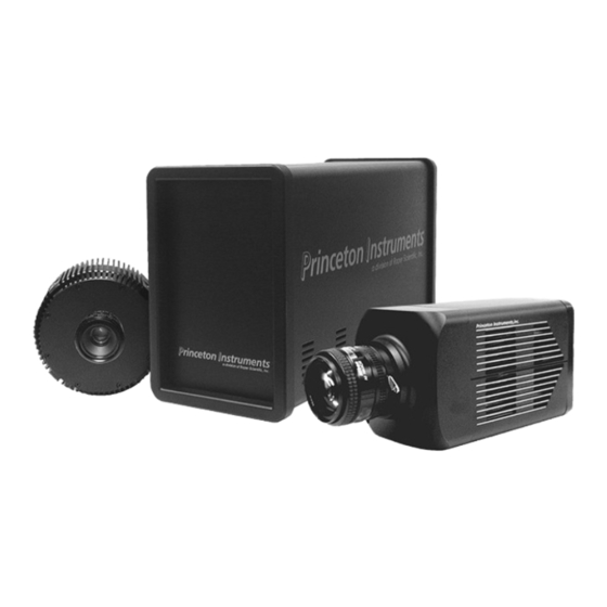
Figure 1. Micromax Cameras and Controller
9
About this Manual
12
Environmental Conditions
13
Grounding and Safety
13
Precautions
14
Repairs
14
Cleaning
14
Princeton Instruments Customer Service
15
Chapter 2 Installation Overview
17
Figure 2. Standard System Diagram
18
Chapter 3 System Setup
19
Unpacking the System
19
Checking the Equipment and Parts Inventory
19
System Requirements
20
Verifying Controller Voltage Setting
21
Figure 3. Controller Power Input Module
21
Installing the Application Software
22
Setting up a PCI Interface
22
Figure 4. Winview Installation: Interface Card Driver Selection
22
Table 1. PCI Driver Files and Locations
23
Setting up a USB 2.0 Interface
24
Figure 5. Rsconfig Dialog Box
26
Mounting the Camera
27
Figure 6. Hardware Wizard: PVCAM Dialog Box
27
Table 3. Bottom Clamps for Different Microscopes
30
Figure 7. Bottom Clamps
31
Figure 8. Bottom Clamp Secured to Relay Lens
31
Selecting the Shutter Setting
32
Connecting the Interface (Controller-Computer) Cable
33
Figure 9. Shutter Setting for 25Mm Internal Shutter
33
Connecting the Detector-Controller Cable
34
Chapter 4 Operation
35
Introduction
35
EMF and Xenon or Hg Arc Lamps
35
Vacuum
35
Cooling
35
Baseline Signal
36
Figure 10. Winspec/32 Detector Temperature Dialog Box
36
Analog Gain Control
37
Imaging Field of View
38
RS-170 or CCIR Video
38
Figure 11. Imaging Field of View
38
Figure 12. Monitor Display of CCD Image Center Area
39
USB 2.0 and System On/Off Sequences
40
First Light (Imaging)
40
Figure 13. Standard System Connection Diagram
41
First Light (Spectroscopy)
45
Figure 14. F-Mount Focus Adjustment
45
Getting Started
46
Setting the Parameters
46
Chapter 5 Timing Modes
51
Fast and Safe Speed Modes
51
Standard Timing Modes
52
Figure 15. Chart of Safe and Fast Mode Operation
53
Figure 16. Free Run Timing Chart (Part of the Chart in Figure 15)
54
Figure 17. Free Run Timing Diagram
54
Figure 19. External Sync Timing Diagram (- Edge Trigger)
55
Figure 20. Continuous Cleans Flowchart
56
Frame Transfer Operation
57
Figure 21. Continuous Cleans Timing Diagram
57
Figure 22. Frame Transfer Where T W1 + T Exp + T C < T R
58
Interline Operation
59
Figure 23. Frame Transfer Where T W1 + T Exp + T C > T R
59
Figure 24. Frame Transfer Where Pulse Arrives after Readout
59
Figure 25. Overlapped Mode Where T W1 + T Exp + T C < T R
61
Figure 27. Overlapped Mode Where Pulse Arrives after Readout
61
Chapter 6 Exposure and Readout
63
Exposure
63
Figure 28. Block Diagram of Light Path in System
63
Figure 29. CCD Exposure with Shutter Compensation
64
Array Readout
67
Figure 30. Full Frame at Full Resolution
67
Table 6. Approximate Readout Time for the Full-Frame CCD Array
68
Figure 31. Frame Transfer Readout
69
Figure 32. Overlapped Mode Exposure and Readout
71
Figure 33. Non-Overlapped Mode Exposure and Readout
72
Table 8. Approximate Readout Time for the Interline CCD Arrays
73
Figure 34. 2 × 2 Binning for Full Frame CCD
74
Figure 35. 2 × 2 Binning for Interline CCD
75
Digitization
76
Chapter 7 Micromax DIF Camera (Double Image Feature)
77
Introduction
77
Timing Modes
78
Figure 36. Free Run Mode Timing Diagram
79
Figure 37. Setup Using to Trigger an Event
79
Figure 38. Timing for Experiment Setup Shown in Figure 37
79
Figure 39. Timing Diagram for Typical IEC Measurement
81
Figure 40. Setup for IEC Experiment with Two Lasers
81
Figure 41. Timing Diagram for IEC Experiment with Two Lasers
81
Figure 42. Another Hardware Setup for an IEC Measurement
82
Figure 43. EEC Timing Example with Exposure Time in Software Set to T Exp
83
Tips and Tricks
84
Figure 44. ESABI Timing Example: Image Exposure Time = T Exp Set in Software
84
Chapter 8 TTL Control
87
Introduction
87
TTL in
87
Buffered Vs. Latched Inputs
88
TTL out
88
TTL Diagnostics Screen
89
Hardware Interface
89
Figure 45. TTL In/Out Connector
89
Table 12. TTL In/Out Connector Pinout
89
Chapter 9 System Component Descriptions
91
Micromax Camera
91
ST-133 Controller
94
Figure 46. Controller Front Panel
94
Figure 47. ST-133 Rear Panel
95
Table 13. ST-133 Shutter Drive Selection
97
Figure 48. Shutter Compensation Times
98
Cables
99
Interface Card
99
Application Software
99
User Manuals
100
Chapter 10 Troubleshooting
101
Introduction
101
Baseline Signal Suddenly Changes
102
Changing the ST-133'S Line Voltage and Fuses
102
Controller Is Not Responding
103
Cooling Troubleshooting
103
Data Loss or Serial Violation
104
Data Overrun Message
104
Demo Is Only Choice on Hardware Wizard:interface Dialog
105
Demo, High Speed PCI, and PCI(Timer) Are Choices on Hardware Wizard:interface Dialog
106
Figure 55. Rsconfig Dialog Box: Two Camera Styles
107
Detector Stops Working
108
Detector Temperature, Acquire, and Focus Are Grayed out
108
Error Creating Controller Message
109
Error Occurs at Computer Powerup
110
Table 14. I/O Address & Interrupt Assignments before Installing Serial Card
111
Table 15. I/O Address & Interrupt Assignments after Installing Serial Card
111
No CCD Named in the Hardware Wizard:CCD Dialog
112
Removing/Installing a Plug-In Module
113
Shutter Malfunctions
114
Appendix A Specifications
115
CCD Arrays
115
Table 16. Micromax Model and CCD Types Cross Reference
115
Temperature Control
116
Cooling
116
Mounting
116
Shutters
117
Inputs
117
Outputs
117
Table 17. Shutter Compensation Times
117
Programmable Interface
118
A/D Converter
118
Computer Requirements
118
Miscellaneous
118
Appendix B Outline Drawings
119
Detectors
119
Figure 62. Rectangular Camera Head: F-Mount
120
Figure 64. Rectangular Camera Head: Spectroscopy Mount Without Shutter
122
Figure 65. 1 Mhz and 100Khz/1Mhz Round Head Camera: C-Mount Adapter and Shutter
123
ST-133B Controller
125
ST-133A Controller
125
Appendix C Kinetics Mode
127
Introduction
127
Kinetic Timing Modes
128
Appendix D Virtual Chip Mode
131
Introduction
131
Virtual Chip Setup
132
Table 18. Micromax:512Bft: Virtual Chip Size, Exposure Time, and Frames Per Second
132
System Connection Diagram
133
Experimental Timing
136
Virtual Chip Dialog Box
136
Tips
137
Appendix E Repumping the Vacuum
139
Introduction
139
Requirements
139
Vacuum Pumpdown Procedure
140
Appendix F Spectrometer Adapters
143
Acton (NTE with or Without Shutter)
144
Chromex 250 IS (NTE with or Without Shutter)
145
ISA HR 320 (NTE with or Without Shutter)
146
ISA HR 640 (NTE with or Without Shutter)
147
JY TRIAX Family (NTE Without Shutter)
148
SPEX 270M (NTE with or Without Shutter)
149
SPEX 500M (NTE with or Without Shutter)
150
SPEX Triplemate (NTE with or Without Shutter)
151
Appendix G USB 2.0 Limitations
153
Table 19. Features Not Supported under USB 2.0
153
Declarations of Conformity
155
Declaration of Conformity
156
Warranty & Service
159
Limited Warranty
159
Contact Information
162
Index
163
Advertisement
Advertisement
Related Products
Princeton Instruments MICROMAX SYSTEM
Princeton Instruments Categories
Security Camera
Digital Camera
Measuring Instruments
Laboratory Equipment
Security System
More Princeton Instruments Manuals
Login
Sign In
OR
Sign in with Facebook
Sign in with Google
Upload manual
Upload from disk
Upload from URL