Sign In
Upload
Manuals
Brands
oventrop Manuals
Water System
Regumaq X-25
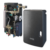
oventrop Regumaq X-25 Fresh Water Station Manuals
Manuals and User Guides for oventrop Regumaq X-25 Fresh Water Station. We have
3
oventrop Regumaq X-25 Fresh Water Station manuals available for free PDF download: Operating Instructions Manual
oventrop Regumaq X-25 Operating Instructions Manual (64 pages)
Brand:
oventrop
| Category:
Industrial Equipment
| Size: 4 MB
Table of Contents
Table of Contents
3
Contact
7
Symbols Used
7
Declaration of Conformity
7
General Information
7
Scope of Delivery
7
Availability of the Instructions
7
Validity of the Instructions
7
Type Plate
7
Safety-Related Information
8
Intended Use
8
Modifications to the Product
8
Explanation of the Warnings
8
Safety Instructions
8
Danger to Life Due to Legionella Formation
8
Danger to Life Due to Electric Current
8
Risk of Injury Due to the Weight of the Product
9
Risk of Damage to Property Due to Incorrect Operation
9
Risk of Injury from Improper Work
9
Damage to Property Due to Unsuitable Location
9
Risk of Burns on Hot Components and Surfaces
9
Risk of Injury from Pressurised Components
9
Risk of Scalding Due to Hot Water
9
Danger Due to Insufficient Personnel Qualification
9
Technical Description
10
Design
10
Station Design
10
Fig. 1: Station Design
10
Fig. 2: Product Assembly Design
11
Product Assembly Design
11
Functional Description
12
Installation Schemes
12
Installation Scheme with a Storage Cylinder and a Fresh Water Station
12
Fig. 3: Installation Scheme with a Storage Cylinder and a Fresh Water Station
12
Installation Scheme with a Storage Cylinder and Two Fresh Water Stations
13
Application Example
13
Fig. 4: Installation Scheme with a Storage Cylinder and Two Fresh Water Stations
13
Technical Data
14
Fig. 6: Dimensions Regumaq X-25 Lower Shell with Product Assembly
15
Dimensions in MM
15
Fig. 5: Dimensions Regumaq X-25 with Upper Shell
15
Fig. 7: Dimensions Regumaq X-25 Side View
16
Fig. 8: Dimensions Regumaq X-25 Wall Bracket
16
Terminal Assignment of the Controller
17
Fig. 9: Terminal Assignment
17
Accessories and Spare Parts
18
Transport and Storage
18
Required Tools
19
Wall Mounting of the Station
19
Notes on Mounting
19
Mounting
19
Fig. 10: Removal of the Upper Shell
20
Fig. 11: Dismantling of the Wall Bracket
20
Fig. 12: Use of the Wall Bracket as Drilling Template
20
Fig. 13: Position of the Washer
20
Piping
21
Fig. 14: Functional Description
21
Fig. 16: Internal Design of the Buffer Storage Cylinder
22
Fig. 15: Connection of the Storage Cylinder Circuit Supply to the Buffer Storage Cylinder
22
Protective Equipotential Bonding/Earthing
22
Commissioning
23
Filling and Venting of the Storage Cylinder Circuit
23
Fig. 17: Equipotential Bonding
23
Fig. 18: Filling and Venting of the Storage Cylinder Circuit
23
Filling and Venting of the Potable Water Circuit
24
Fig. 19: Filling and Venting of the Potable Water Circuit
24
Power Supply Without the Pre-Assembled Mains Connection Cable
25
Power Supply through the Pre-Assembled Mains Connection Cable
25
Electrical Connection
25
Fig. 20: Removal of the Controller from the Lower Shell
26
Fig. 21: Mounting Position
26
Fig. 22: Opening of the Controller
26
Configuration of the Circulation Function (Optional)
27
Fig. 23: Cable Channels in the Lower Shell
27
Fig. 24: Fuse Holder and DIP Switches
27
Fig. 28: Thermally Controlled Circulation
28
Fig. 27: 24-Hour Circulation Mode
28
Fig. 26: Circulation Activated
28
Fig. 25: Circulation Deactivated
28
Extension of the Maximum Adjustable Temperature
28
Handover to the Operator
29
Fig. 29: Hot Water Temperature up to 60°C (Default)
29
Fig. 30: Hot Water Temperature up to 75°C
29
Fig. 31: Displays and Control Elements
30
Emergency Mode (Manual Mode)
30
Setting of the Hot Watersetpoint Temperature
30
Controller Presettings
30
Displays and Control Elements
30
Operation
30
Blocking Protection
31
Replacement of the Fuse
31
Fig. 32: DIP Switch Emergency Mode
31
Troubleshooting
32
Troubleshooting Table
32
Nominal Resistances of the Temperature Sensors
33
Error Messages on the Display
33
Control LED
33
Displays and Error Messages
33
Decalcification of the Heat Exchanger
34
Decalcification of the Potable Water Circuit with the Heat Exchanger Installed
34
Cleaning of the Heat Exchanger (Storage Cylinder Circuit Side)
35
Decalcification of the Removed Heat Exchanger
36
Fig. 33: Decalcification of the Removed Heat Exchanger
36
Fig. 34: Potable Water Circuit
37
Cleaning of the Measuring Turbine
37
Required Tools
37
Cleaning of the Volume Flow Sensor
37
Fig. 35: Cleaning of the Measuring Turbine
38
Fig. 36: Circlip
38
Fig. 37: Loosening of the Measuring Turbine
39
Fig. 38: Installation of the Measuring Turbine
39
Replacement of the Potable Water Filter Insert
40
Functional Control of the Check Valve of the Circulation Set
40
Electrical Components and Plug Connections
40
Actuation of the Four Shutoff Ball Valves
40
Water Sampling
40
Maintenance
40
Functional Check of the Safety Valves (Potable Water Circuit)
40
Leakage Check (Visual Inspection)
40
System Pressure Check
40
Notes for the Operator
41
Dismantling and Disposal
42
Dismantling of the Station
42
Disconnection of the Station from the Power Supply
42
Disposal
42
List of Figures 13. List of Figures
43
List of Figures
44
Appendix
45
Characteristic Line for Wilo Circulation Pump
45
Fig. 39: Characteristic Line for Wilo Circulation Pump (Storage Cylinder Circuit)
45
Fig. 40: Characteristic Line - Pressure Loss During Hot Potable Water Preparation
45
Fig. 41: Characteristic Line - Pressure Loss During Hot Potable Water Preparation (Potable Water Circuit)
45
Characteristic Line for Hot Potable Water Preparation
46
Fig. 42: Storage Cylinder Circuit Volume Flow - Heating of Potable Water to 45 °C
46
Fig. 43: Storage Cylinder Circuit Return Temperature - Heating of Potable Water to 45 °C
46
Heating of Potable Water from 10 °C to 45 °C
46
Fig. 44: Storage Cylinder Circuit Volume Flow - Heating of Potable Water to 50 °C
47
Fig. 45: Storage Cylinder Circuit Return Temperature - Heating of Potable Water to 50 °C
47
Heating of Potable Water from 10 °C to 50 °C
47
Fig. 46: Storage Cylinder Circuit Volume Flow - Heating of Potable Water to 55 °C
48
Fig. 47: Storage Cylinder Circuit Return Temperature - Heating of Potable Water to 55 °C
48
Heating of Potable Water from 10 °C to 55 °C
48
Fig. 48: Storage Cylinder Circuit Volume Flow - Heating of Potable Water to 60 °C
49
Fig. 49: Storage Cylinder Circuit Return Temperature - Heating of Potable Water to 60 °C
49
Heating of Potable Water from 10 °C to 60 °C
49
Fig. 50: Storage Cylinder Circuit Volume Flow - Heating of Potable Water to 65 °C
50
Fig. 51: Storage Cylinder Circuit Return Temperature - Heating of Potable Water to 65 °C
50
Heating of Potable Water from 10 °C to 65 °C
50
Fig. 52: Storage Cylinder Circuit Volume Flow - Heating of Potable Water to 70 °C
51
Fig. 53: Storage Cylinder Circuit Return Temperature - Heating of Potable Water to 70 °C
51
Heating of Potable Water from 10 °C to 70 °C
51
Fig. 54: Storage Cylinder Circuit Volume Flow - Heating of Potable Water to 75 °C
52
Fig. 55: Storage Cylinder Circuit Return Temperature - Heating of Potable Water to 75 °C
52
Heating of Potable Water from 10 °C to 75 °C
52
EU Declaration of Conformity
53
Water Quality Requirements
54
Handover Report
56
Maintenance Report
58
Advertisement
oventrop Regumaq X-25 Operating Instructions Manual (68 pages)
Fresh water station
Brand:
oventrop
| Category:
Water System
| Size: 8 MB
Table of Contents
Table of Contents
3
1 General Information
6
Validity of the Operating Instructions
6
Type Plate
6
Extent of Supply
6
Contact
6
Declaration of Conformity
6
Used Symbols
6
2 Safety-Related Information
7
Correct Use
7
Modifications to the Product
7
Warnings
7
Safety Notes
8
Danger to Life Due to Development of Legionella
8
Danger to Life Due to Electric Current
8
Danger in Case of Inadequate Personnel Qualification
8
Risk of Scalding Due to Hot Water
8
Risk of Injury from Pressurised Components
8
Risk of Burns Due to an Uncontrolled Escape of Hot Fluids
8
Risk of Burns Due to Hot Components and Surfaces
8
Risk of Injury Due to the Weight of the Product
8
Risk of Injury in Case of Improper Work
8
Damage to Property Due to an Unsuitable Installation Location
9
Damage to Property Due to Incorrect Operation
9
Availability of the Operating Instructions
9
3 Technical Description
10
Construction
10
Functional Description
12
System Diagram
12
Example of the Application
14
Technical Data
14
Front View
16
Side View
17
Wall Bracket
18
Controller Terminal Assignment
19
4 Accessories and Spare Parts
20
Potable Water Circulation Set
20
Sealing Set
20
Load Relay
20
Water Sampling Valve Aquastrom P
20
Non-Return Check Valve Aquastrom R
21
Strainer
21
Water Filter Aquanova Magnum
21
Grounding Clip
21
Connection Fittings
21
5 Transport and Storage
22
6 Installation
22
Advice Regarding Installation
22
Wall Attachment of the Station
23
Required Tools
23
Installation
23
Pipework
25
Protective Equipotential Bonding/Grounding
27
7 Commissioning
28
Filling and Bleeding of the Storage Cylinder Circuit
28
Filling and Bleeding of the Potable Water Circuit
29
Electrical Connection
29
Power Supply Via Pre-Assembled Power Supply Cable
30
Power Supply Without Pre-Assembled Power Supply Cable
30
Configuration of the Circulation Function (Optional)
32
Activation of the Circulation Function
32
Operating Mode of the Circulation Pump
32
Handover to the User
33
8 Operation
34
Setting of the Nominal Hot Water Temperature
34
Emergency Operation (Manual Operation)
34
Anti-Lock Protection
35
Displays
35
Error Messages on the Display
35
Control LED
35
Replacement of the Fuse
35
9 Troubleshooting
37
Troubleshooting Table
37
Nominal Resistances of the Temperature Sensors
38
Decalcification of the Heat Exchanger
39
Decalcification of the Potable Water Side after Installation
39
Cleaning of the Heat Exchanger (Storage Cylinder Circuit Side)
40
Decalcification of the Dismounted Heat Exchanger
41
Cleaning of the Flow Sensor
42
Required Tools
42
Cleaning of the Measuring Turbine
42
10 Maintenance
45
Leak Check (Visual Inspection)
45
System Pressure Check
45
Functional Check Of The Safety Valves (Potable Water Circuit)
45
Water Sampling
45
Actuation of the Four Isolating Ball Valves
45
Electronic Components and Plug-In Connections
45
Functional Check of the Check Valve of the Circulation Set
45
Replacement Of The Potable Water Filter Insert
46
11 Advice for the User
46
12 Removal and Disposal
47
Dismantling of the Fitting
47
Disconnection of the Station from the Power Supply
47
Removal of the Station
47
Disposal
47
13 Illustration Index
48
14 Appendix
50
Characteristic Line for Wilo Circulation Pump
50
Characteristic Lines for Potable Water Heating
51
Heating of Potable Water from 10 °C to 45 °C
51
Heating of Potable Water from 10 °C to 50 °C
52
Heating of Potable Water from 10 °C to 55 °C
53
Heating of Potable Water from 10 °C to 60 °C
54
Heating of Potable Water from 10 °C to 65 °C
55
Heating of Potable Water from 10 °C to 70 °C
56
Heating of Potable Water from 10 °C to 75 °C
57
EU Declaration of Conformity
58
15 Advice Regarding Corrosion Protection
59
16 Handover Report
61
17 Maintenance Report
63
oventrop Regumaq X-25 Operating Instructions Manual (28 pages)
Controller for fresh water stations
Brand:
oventrop
| Category:
Plumbing Product
| Size: 0 MB
Table of Contents
Deutsch
3
Table of Contents
3
1 Allgemeine Angaben
5
Gültigkeit der Anleitung
5
Typenschild
5
Lieferumfang
5
Kontakt
5
Konformitätserklärung
5
Verwendete Symbole
5
2 Sicherheitsbezogene Informationen
6
Bestimmungsgemäße Verwendung
6
Warnhinweise
6
Sicherheitshinweise
6
Lebensgefahr durch Elektrischen Strom
6
Gefahr durch Unzureichende Personalqualifikation
6
Verbrennungsgefahr an Heißen Armaturen und Oberflächen
7
Verfügbarkeit der Betriebsanleitung
7
3 Technische Beschreibung
7
4 Transport und Lagerung
7
5 Montage
8
Austausch Vorbereiten
8
Regler Austauschen
8
6 Entsorgung
10
English
11
1 General Information
13
Validity of the Operating Instruction
13
Type Plate
13
Extent of Supply
13
Contact
13
Declaration of Conformity
13
Symbols Used
13
2 Safety-Related Information
14
Correct Use
14
Warnings
14
Safety Notes
14
Danger to Life Due to Electric Current
14
Danger Caused by Inadequately Qualified Personnel
14
Risk of Burns Due to Hot Components and Surfaces
15
Availability of the Operating Instructions
15
3 Technical Description
15
4 Transport and Storage
15
5 Installation
16
Preparation of the Replacement
16
Replacement of the Controller
16
6 Disposal
18
Français
19
1 Généralités
21
Validité de la Notice
21
Plaque Signalétique
21
Composants Fournis
21
Contact
21
Déclaration de Conformité
21
Symboles Utilisés
21
2 Informations Relatives À la Sécurité
22
Utilisation Conforme
22
Avertissements
22
Consignes de Sécurité
22
Risque de Mort Lié Au Courant Électrique
22
Danger Lié À un Manque de Qualification
22
Risque de Brûlure Lié Aux Robinetteries Et Surfaces Chaudes
23
Disponibilité de la Notice D'utilisation
23
3 Description Technique
23
4 Transport Et Stockage
23
5 Montage
24
Préparation du Remplacement
24
Remplacement du Régulateur
24
6 Traitement des Déchets
26
Advertisement
Advertisement
Related Products
oventrop Regusol X-2S
oventrop X-45
oventrop Regumaq X-80
oventrop Regumaq K
oventrop OVSOL System 5
oventrop Categories
Control Unit
Controller
Plumbing Product
Thermostat
Temperature Controller
More oventrop Manuals
Login
Sign In
OR
Sign in with Facebook
Sign in with Google
Upload manual
Upload from disk
Upload from URL