Sign In
Upload
Manuals
Brands
OMRON Manuals
I/O Systems
SYSMAC CJ1W-PRM21
OMRON SYSMAC CJ1W-PRM21 Manuals
Manuals and User Guides for OMRON SYSMAC CJ1W-PRM21. We have
3
OMRON SYSMAC CJ1W-PRM21 manuals available for free PDF download: Operation Manual
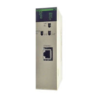
Omron SYSMAC CJ1W-PRM21 Operation Manual (317 pages)
10Base-5, 10Base-T Ethernet Units
Brand:
Omron
| Category:
Network Hardware
| Size: 3 MB
Table of Contents
Table of Contents
6
Precautions
16
General Precautions
17
Intended Audience
17
Safety Precautions
17
Application Precautions
18
Operating Environment Precautions
18
Conformance to EC Directives
20
Section 1 Features and System Configuration
22
Features and System Configuration
22
Features
23
Device Configuration
24
Node Connections
24
System Configuration
24
10Base-5 Ethernet Unit
25
Devices Required in a Network
25
10Base-T Ethernet Unit
26
Related Programming Devices
27
Specifications
28
Software Configuration
31
Allocating IP Addresses
33
IP Address Configuration
33
IP Addresses
33
IP Address Settings
34
Subnet Masks
34
Ethernet and IEEE802.3 Standards
35
Installation
35
Precautions
35
Section 2 Communications Functions
36
Communications Functions
36
Communications Functions
37
Ethernet Unit Functions
38
Socket Ports Used by the Ethernet Unit
38
FINS Communications
39
Selecting Communications Services
39
Socket Services
40
FTP Server
42
Mail
42
Section 3 Installation and Initial Setup
44
Installation and Initial Setup
44
Automatic Address Generation
45
Before Operation
45
IP Address Table
46
Overview of Startup Procedure
47
Unit Components
49
Nomenclature
50
Indicators
53
CS-Series Ethernet Units
54
Switch Settings
54
CJ-Series Ethernet Units
56
Mounting to a CS-Series PC
58
Mounting to a PC
58
Mounting to a CJ-Series PC
59
Connecting to the Network
60
Ethernet Connectors
60
Ethernet Network Installation
60
Connecting the Cable
61
Connecting the Power Supply (CS1W-ETN01 Only)
63
Connecting Programming Devices to the PC
66
Creating an I/O Table
66
I/O Table Overview
66
Procedure for Creating an I/O Table
66
Creating Routing Tables
67
Routing Table Overview
67
Connecting and Using a Peripheral Device for the PC
69
CPU Bus Unit System Setup Defaults
72
System Setup
72
Using a Programming Device
72
When Settings Are Required
72
Creating an IP Address Table
73
Creating an IP Router Table
73
Checking Communications
74
Internode Test
74
PING Command
74
PING Command and Internode Testing
74
Simple Startup Test Example
75
Section 4 System Setup and Memory Allocations
78
System Setup and Memory Allocations
78
Allocated Words
79
CPU Bus Unit System Setup
80
Settings
81
Mail Settings
85
CIO Area Allocations
88
DM Area Allocations
94
Section 5 Fins Communications
100
FINS Communications
100
Communications on an Ethernet Network
101
FINS Communications Service Features
101
Overview of FINS Communications
101
Procedure before Using FINS Communications
103
Communications Specifications
104
Sending Commands from a PC
104
Program Example
113
Transmission Delays
114
Designating Remote Addresses
117
Sending Commands from a Host Computer
117
FINS Frames
118
Sample Program
120
Delays for Accessing PC Memory
122
FINS Server
123
Section 6
124
Socket Services
124
Overview
125
Socket Service Functions
125
Socket Port Numbers
126
Sockets
126
Using Sockets with the Ethernet Unit
126
Differences between TCP and UDP
127
Opening TCP Sockets
128
Fragmentation of Send Data
129
Maximum Transmission Delays
131
Precautions in Using Socket Services
132
Using Socket Services with Socket Service Request Switches
133
Socket Service Parameters
135
Response Codes
138
Socket Service Request Switches
143
UDP/TCP Socket Status
146
Application Procedure
147
Socket Services and Socket Status
148
Timing Charts
149
TCP/IP Communications Programming Example
151
UDP/IP Communications Programming Example
155
Using Socket Services with CMND(490)
160
UDP/TCP Socket Status
161
Socket Services and Socket Status
164
Communications Timing Chart
165
Socket Service Timing Chart
165
TCP/IP Communications Programming Example
167
UDP/IP Communications Programming Example
174
Section 7 Ftp Server
182
FTP Server
182
Overview
183
Setting Login Names and Passwords
184
Using File Memory
184
FTP Server Application Example
188
Table of Commands
189
Using FTP Commands
189
Using the Commands
190
Error Messages and FTP Status
193
UNIX Application Example
195
Section 8 Mail
198
Mail
198
Overview of Mail Function
199
Mail Contents
200
Mail Triggers
201
Sending Mail
201
Mail Status
202
Mail Example
203
Sending Mail
203
Testing Communications
206
Communications Testing Functions
207
PING Command
207
Internode Test
208
Section 10 Troubleshooting
212
Troubleshooting with Indicators
213
Error Log
215
Error Status
215
Error Log Error Codes
216
Startup Problems
218
Troubleshooting Procedures
218
FINS Communications Problems
219
(Send(090)/Recv(098)/Cmnd(490))
220
UDP Socket Problems
220
TCP Socket Problems
222
FTP Service Problems
223
Network Connection Problems
224
Mail Problems
226
Troubleshooting with Response Codes
228
Results Storage Area Response Codes
231
Section 11 Fins Commands Addressed to Ethernet Units
234
FINS Commands Addressed to Ethernet Units
234
Command Code List
235
Command Codes and Response Codes
235
Response Code List
235
Format
236
Socket Applications
236
PC Memory Areas
237
Command/Response Reference
238
Reset
238
Controller Data Read
239
Controller Status Read
240
Internode Echo Test
241
Broadcast Data Send
242
Broadcast Test Results Read
242
Error Log Read
242
Error Log Clear
244
Udp Open Request
244
Udp Receive Request
245
Udp Send Request
246
Udp Close Request
248
Passive Tcp Open Request
249
Active Tcp Open Request
252
Tcp Receive Request
253
Tcp Send Request
255
Tcp Close Request
256
Ping
257
Ip Address Table Write
258
Ip Address Write
259
Ip Address Table Read
260
Ip Router Table Read
261
Protocol Status Read
262
Memory Status Read
266
Socket Status Read
268
Address Information Read
269
Ip Address Read
270
Network Installation
272
Ethernet Network Parameters
282
Buffer Configuration
284
TCP Status Transitions
286
Auxiliary Area Data
288
CPU Bus Unit Allocations in the CPU Unit
290
ASCII Characters
298
Dimensions
300
Maintenance
304
J Inspections
306
Index
308
Revision History
314
Advertisement
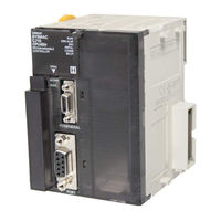
Omron SYSMAC CJ1W-PRM21 Operation Manual (297 pages)
PROFIBUS Master Units
Brand:
Omron
| Category:
Controller
| Size: 5 MB
Table of Contents
Table of Contents
6
About this Manual
10
Precautions
16
General Precautions
17
Intended Audience
17
Safety Precautions
17
Operating Environment Precautions
18
Application Precautions
19
Conformance to EC Directives
21
Applicable Directives
21
Concepts
21
Section 1 Features and Specifications
22
Features and Specifications
22
Overview of PROFIBUS
23
Introduction
23
PROFIBUS Communication Protocol
23
Device Types
25
Bus Access Protocol
25
Diagnostic Functions
26
Protection Mechanisms
27
Network Operation Modes
27
Setting up a PROFIBUS DP Network
28
Configuring the PROFIBUS Master
28
FDT/DTM Technology
28
GSD File Technology
29
PROFIBUS Master Unit
31
PROFIBUS Master Unit Features
31
Specifications
33
Comparison with Previous Model
38
CX-Profibus Configurator
40
CX-Profibus Features
40
Specifications
43
Basic Operating Procedure
45
Overview
45
Preparations for Communications
46
Procedures Prior to Starting Communications
46
Section 2 Installation and Wiring
48
Installation and Wiring
48
Unit Components
49
Nomenclature
49
Indicators
50
Switch Settings
51
PROFIBUS Connector
52
Installing the CS1/CJ1W-PRM21 Units
53
Handling Precautions
53
Mounting the CS1W-PRM21
53
Mounting the CJ1W-PRM21
55
Initial Setup Procedure
56
Selecting a Unit Number
57
Creating an I/O Table
57
Setting up a Network
58
Network Structure
58
Bus Termination
60
PROFIBUS Cable Connector
61
Defining PROFIBUS DP in the Software
62
Shielding Precautions
62
Section 3 Configuration Software
64
Configuration Software
64
Installation
65
Installation Requirements
65
Installation Procedure
65
Installing the C200HW-PRM21 DTM
73
CX-Profibus
74
Starting CX-Profibus
74
CX-Profibus Main Window
75
Device Catalogue
78
Updating the Device Catalogue
80
Adding Devices to the Network
81
Saving and Opening Projects
81
Exporting to HTML
81
Error Logging and FDT Monitoring
82
Access Control and User Management
84
CS1/CJ1W-PRM21 PROFIBUS Master DTM
86
Configuration User Interface
86
Diagnostics User Interface
99
Connecting to the CS1/CJ1W-PRM21
105
C200HW-PRM21 PROFIBUS DP Master DTM
108
Configuration User Interface
108
Diagnostics User Interface
113
Connecting to the C200HW-PRM21
116
Generic Slave Device DTM
117
Configuration User Interface
118
Section 4
123
Diagnostics User Interface
126
Section 4 Allocated Cio and DM Words
130
Allocated CIO and DM Words
130
Overview of Word Allocations
131
CIO Area Word Allocations
132
DM Area Word Allocations
132
Allocated CIO Area Words
133
Software Switches 1 (Word N)
134
Global-Control Message (Word N+2)
135
Unit Status (Word N+4)
138
Master Status 1 (Word N+5)
139
Master Status 2 (Word N+6)
141
Slave Status (Word N+7)
142
Actual Bus Cycle Time (Word N+8)
143
Slave Data_Exchange Active Flags (Word N+9 to Word N+16)
143
Slave New Diagnostics Flags (Word N+17 to Word N+24)
144
Section 5 Fins Commands and Responses
146
FINS Commands and Responses
146
FINS Commands and Responses
147
FINS Message Service Communications
147
Command Code List
148
Response Code List
148
Sending FINS Using CMND
149
Command / Response Reference
150
Memory Area Read (0101)
150
Run (0401)
151
Stop (0402)
152
Controller Data Read (0501)
153
Error Log Read (2102)
153
Explicit Message Send (2801)
155
Error Log Clear (0203)
155
Profibus Message Send (2809)
157
Section 6 Operation
168
Operation
168
Introduction
169
Setting up a Network
169
Adding Devices to the Network
171
Changing Device and DTM Addresses
173
Configuring the Slave Devices
176
Defining the I/O Configuration
176
Setting Parameters
179
Selecting the Group Assignment
180
Configuring the Master
182
Setting the Master Parameters
182
Setting the Bus Parameters
184
Defining and Changing I/O Mapping
185
Configuring CX-Server
186
Downloading the Configuration
188
I/O Communication Characteristics
189
I/O Data Configuration
189
Mapping I/O Data
189
Supported Data Types
196
Exchanging I/O Data over PROFIBUS
197
PLC Cycle Time Performance
199
I/O Response Time
199
System Startup Time
202
Operating the Network
203
User Access to the Network
203
Changing PROFIBUS Mode of the Master Unit
204
Transmitting Global-Control Commands
206
Using Auto-CLEAR
210
Monitoring the Network
211
Monitoring the Master Unit and the Network
211
Monitoring Slave Status
215
Using the Error Log
216
PROFIBUS DP-V1 Services
218
Section 7 Troubleshooting and Maintenance
222
Troubleshooting and Maintenance
222
Overview
223
Troubleshooting Using LED Indicators
224
LED Indicators
224
Unit Start-Up Errors
224
Unit Operational Errors
226
Unit Configuration Errors
227
Network Errors
228
Troubleshooting Using Error Status
230
Unit Status Word
230
Master Status 2 Word
231
Troubleshooting the Network
233
Troubleshooting Parameter Download
233
Troubleshooting the Network Using CX-Profibus
234
Troubleshooting I/O Communication
239
Troubleshooting PROFIBUS DP-V1 Communication
242
Troubleshooting Using the Error Log
243
Error Log Overview
243
Error Codes
244
Troubleshooting FINS Commands
246
Maintenance
247
Cleaning
247
Inspection
247
Replacing the Unit
248
Replacement Precautions
248
Setting the Unit after Replacement
248
Addition/Replacement of Units on the PROFIBUS Network
248
Bus Parameters
250
Slave Diagnostics Message
254
I/O Data Conversions
264
Configurator Error and Warning Messages
268
Memory Card Backup Functions
274
Application Notes
276
C200HW-PRM21 Notes
278
Index
286
Revision History
292
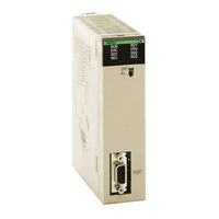
OMRON SYSMAC CJ1W-PRM21 Operation Manual (190 pages)
SYSMAC CS/CS series
Brand:
OMRON
| Category:
I/O Systems
| Size: 1 MB
Table of Contents
Table of Contents
5
About this Manual
7
Precautions
9
General Precautions
10
Intended Audience
10
Safety Precautions
10
Application Precautions
11
Operating Environment Precautions
11
Conformance to EC Directives
13
Applicable Directives
13
Concepts
13
Conformance to EC Directives
14
Section 1 Features and Specifications
15
Features and Specifications
15
Overview of PROFIBUS
16
Introduction
16
PROFIBUS Communication Protocol
16
Device Types
18
Bus Access Protocol
18
Diagnostic Functions
19
Protection Mechanisms
20
Network States
20
Setting up a PROFIBUS-DP Network
21
Configuring the PROFIBUS-DP Master
21
FDT/DTM Technology
21
GSD File Technology
22
PROFIBUS-DP Master Unit
23
PROFIBUS-DP Master Unit Features
23
Specifications
24
Comparison with Previous Model
28
CX-Profibus Configurator
30
CX-Profibus Features
30
Specifications
32
Basic Operating Procedure
34
Overview
34
Preparations for Communications
35
Procedures Prior to Starting Communications
35
Section 2 Installation and Wiring
37
Installation and Wiring
37
Unit Components
38
Nomenclature
38
Indicators
39
Switch Settings
40
PROFIBUS Connector
41
Installing the PROFIBUS-DP Master Unit
42
Handling Precautions
42
Mounting the CS1W-PRM21
42
Mounting the CJ1W-PRM21
44
Initial Setup Procedure
45
Selecting a Unit Number
46
Creating an I/O Table
46
Setting up a Network
47
Network Structure
47
Bus Termination
50
PROFIBUS Cable Connector
50
Defining PROFIBUS-DP in the Software
51
Shielding Precautions
51
Section 3 Configuration Software
53
Configuration Software
53
Installation
54
Installation Requirements
54
Installation Procedure
54
CX-Profibus
61
Starting CX-Profibus
61
CX-Profibus Main Window
62
Device Catalogue
65
Updating the Device Catalogue
67
Saving and Opening Projects
67
Adding Devices to the Network
68
Exporting to HTML
69
Error Logging and FDT Monitoring
70
Access Control and User Management
71
PROFIBUS-DP Master DTM
74
Configuration User Interface
74
Diagnostics User Interface
82
Connecting to the PROFIBUS-DP Master Unit
88
Generic Slave Device DTM
91
Configuration User Interface
91
Diagnostics User Interface
94
Section 4 Allocated Cio and DM Words
97
Allocated CIO and DM Words
97
Overview of Word Allocations
98
CIO Area Word Allocations
99
DM Area Word Allocations
99
Allocated CIO Area Words
100
Software Switches 1 (Word N)
101
Global_Control Message (Word N+2)
102
Unit Status (Word N+4)
104
Master Status 1 (Word N+5)
106
Master Status 2 (Word N+6)
107
Slave Status (Word N+7)
109
Actual Bus Cycle Time (Word N+8)
109
Slave Data_Exchange Active Flags (Word N+9 to Word N+16)
110
Slave New Diagnostics Flags (Word N+17 to Word N+24)
111
Section 5 Fins Commands and Responses
113
Fins Commands and Responses
113
FINS Commands and Responses
114
FINS Message Service Communications
114
Command Code List
114
Response Code List
114
Sending FINS Using CMND
115
Command / Response Reference
116
Memory Area Read (0101)
116
Run (0401)
117
Stop (0402)
118
Controller Data Read (0501)
119
Error Log Read (2102)
119
Error Log Clear (0203)
121
Section 6 Operation
123
Operation
123
Introduction
124
Setting up a Network
124
Adding Devices to the Network
126
Changing Station Addresses
128
Configuring the Slave Stations
129
Defining the I/O Configuration
129
Setting Parameters
131
Selecting the Group Assignment
132
Configuring the Master
133
Setting the Master Parameters
134
Setting the Bus Parameters
135
Defining and Changing I/O Mapping
136
Section 7 Troubleshooting and Maintenance
141
Troubleshooting and Maintenance
141
Overview
142
Troubleshooting Using LED Indicators
143
LED Indicators
143
Unit Start-Up Errors
143
Unit Operational Errors
145
Unit Configuration Errors
146
Network Errors
147
Troubleshooting I/O Communication
149
Troubleshooting Using Error Status
152
Unit Status Word
152
Master Status 2 Word
153
Troubleshooting Using the Error Log
155
Error Log Overview
155
Error Codes
156
Troubleshooting FINS Commands
157
Maintenance
158
Cleaning
158
Inspection
158
Replacing the Unit
159
Replacement Precautions
159
Setting the Unit after Replacement
159
Addition/Replacement of Units on the PROFIBUS Network
159
Bus Parameters
161
Slave Diagnostics Message
165
Memory Card Backup Functions
175
I/O Data Conversions
177
Configurator Error and Warning Messages
181
E Configurator Error and Warning Messages
186
Index
187
Revision History
189
Advertisement
Advertisement
Related Products
Omron CJ1W-PDC15
Omron CJ1W-PH41U
Omron CJ1W-AD041-V1
Omron CJ1W-AD081-V1
Omron SYSMAC CJ1W-AD04U
Omron SYSMAC CJ1W-AD04U-SL
omron CJ1W-DA041
omron CJ1W-DA08V
omron CJ1W-DA08C
omron CJ1W-MAD42
OMRON Categories
Blood Pressure Monitor
Controller
Accessories
Switch
Inverter
More OMRON Manuals
Login
Sign In
OR
Sign in with Facebook
Sign in with Google
Upload manual
Upload from disk
Upload from URL