Sign In
Upload
Manuals
Brands
Omron Manuals
Industrial PC
NJ501-5300
Omron NJ501-5300 Manuals
Manuals and User Guides for Omron NJ501-5300. We have
2
Omron NJ501-5300 manuals available for free PDF download: User Manual, Instruction & Reference Manual
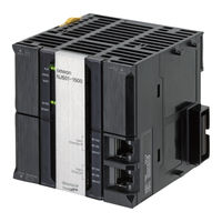
Omron NJ501-5300 User Manual (306 pages)
Machine Automation Controller
Brand:
Omron
| Category:
Controller
| Size: 7.29 MB
Table of Contents
Introduction
3
Relevant Manuals
4
Manual Structure
6
Sections in this Manual
9
Table of Contents
10
Terms and Conditions Agreement
14
Safety Precautions
16
Precautions for Safe Use
22
Precautions for Correct Use
32
Regulations and Standards
36
Versions
38
Related Manuals
41
Terminology
43
Revision History
48
Introduction to NJ-Series Controllers
51
The NJ-Series Controllers
52
Features
52
Introduction to the System Configurations
54
Specifications
57
Overall Operating Procedure for the NJ-Series Controller
62
Overall Procedure
62
Procedure Details
63
System Configuration
67
Basic System Configuration
68
Ethercat Network Configuration
70
CJ-Series Unit Configuration
71
Connecting to the Sysmac Studio
85
Network Configuration
86
Configuration Units
89
CPU Units
90
Models and Specifications
90
Components and Functions
91
SD Memory Cards
98
Models and Specifications
98
Purpose
98
Installing and Removing
99
Power Supply Units
102
Models and Specifications
102
Components and Functions
104
Selecting a Power Supply Unit
105
CJ-Series Basic I/O Units
110
Models and Specifications
110
Part Names and Functions
111
B7A Interface Ports
114
Overview
114
System Configuration
114
Models
114
B7A Communications Specifications
115
Common Specifications
116
B7A Interface Port I/O Types
116
Parts and Names
117
Transmission Error Processing
119
CJ-Series I/O Control Units and I/O Interface Units
120
Models and Specifications
120
Component and Functions
120
Sysmac Studio
121
Model Numbers
121
Connection
122
Installation and Wiring
125
Processing at Power on and Power off
126
Power on Operation
126
Power off Operation
128
Resetting the Controller from the Sysmac Studio
130
Fail-Safe Circuits
131
Order of Powering up the Controller and Controlled System
132
Mounting Units
134
Installation in a Control Panel
134
Connecting Controller Components
139
DIN Track Installation
141
Connecting CJ-Series Expansion Racks
144
Assembled Appearance and Dimensions
146
Wiring
151
Power Supply Wiring
151
Wiring the Built-In Ethercat Port
156
Wiring CJ-Series Basic I/O Units with Terminal Blocks
157
Wiring CJ-Series Basic I/O Units with Connectors
158
Connecting to Connector-Terminal Block Conversion Units or I/O Relay Terminals
163
Connecting I/O Devices
164
Wiring the Built-In Ethercat Port
167
Wiring B7A Interface Units
168
Control Panel Installation
174
Temperature
174
Humidity
176
Vibration and Shock
176
Atmosphere
176
Electrical Environment
177
Grounding
181
Troubleshooting
187
Overview of Troubleshooting
188
Inspection and Maintenance
189
Periodic Maintenance and Inspection
190
Periodic Inspection
190
Unit Replacement Precautions
191
Replacing the Battery
192
Battery Replacement
192
Operation Without a Battery
195
Appendices
197
Specifications
198
Specifications of Basic I/O Units
199
A-2-1 Overview of Units
199
Basic I/O Units
201
A-2-3 Precautions on Contact Output Units
248
Connecting Connector-Terminal Block Conversion Units and I/O Relay Terminals
250
Dimensions
285
A-3-1 NJ-Series CPU Units
285
A-3-2 NJ-Series Power Supply Units
286
A-3-3 CJ-Series Basic I/O Units
287
A-3-4 B7A Interface Unit
290
A-3-5 CJ-Series I/O Control Unit and I/O Interface Unit
290
A-3-6 SD Memory Card
290
Load Short-Circuit Protection and Line Disconnection Detection for CJ-Series Basic I/O Units
291
A-4-1 Load Short-Circuit Protection and Line Disconnection Detection for CJ1W-OD202
291
A-4-2 Load Short-Circuit Protection for CJ1W-OD204/OD212/OD232/MD232
294
EMC Directive Measures for Relay Outputs
296
System-Defined Variables Related to Hardware
298
Version Information
299
Relationship between Hardware Revisions of CPU Units and Sysmac Studio Versions
299
Performance Improvements for Unit Version Upgrades
299
Advertisement
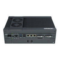
Omron NJ501-5300 Instruction & Reference Manual (142 pages)
NJ/NY-series, Machine Automation Controller, Industrial PC Platform, G code
Brand:
Omron
| Category:
Industrial PC
| Size: 1.3 MB
Table of Contents
Introduction
3
Intended Audience
3
Applicable Products
3
Relevant Manuals
4
Relevant Manuals for NJ Series
4
Relevant Manuals for NY Series
6
Manual Structure
7
Page Structure and Symbols
7
Special Information
8
Sections in this Manual
9
Table of Contents
10
Terms and Conditions Agreement
14
Warranty, Limitations of Liability
14
Application Considerations
15
Disclaimers
15
Safety Precautions
16
Precautions for Safe Use
17
Precaution for Correct Use
18
Regulations and Standards
19
Versions
20
Checking Versions
20
Related Manuals
23
Terminology
26
Revision History
27
Basic Information on NC Programming
29
Instructions
30
G Codes
30
M Codes
32
Instruction Parameters
33
G Code Descriptions
35
What Is Modal
37
G Code
39
Section 2 G Code
41
Interpolation Functions
41
G00 Rapid Positioning
42
G01 Linear Interpolation
44
G02, G03 Circular Interpolation
46
G31 Skip Function
51
Dwell
53
G04 Dwell
54
Feed Functions
55
Feedrate Function (F Function)
56
Acceleration Time, Deceleration Time, Jerk Time
57
G09 Exact Stop
58
G61 Exact Stop Mode
59
G64 Continuous-Path Mode
60
G500, G501 Multi-Block Acceleration/Deceleration Rate
62
Coordinate System
65
G52 Local Coordinate System Set
66
G53 Dimension Shift Cancel
67
G54 to G59 Select Work Coordinate System
68
G17, G18, G19 Plane Selection
69
G20 Inch Input, G21 Metric Input
70
G90 Absolute Dimension, G91 Incremental Dimension
71
Reference Point
73
G28 Return to Reference Point
74
G30 Return to 2Nd, 3Rd and 4Th Reference Point
76
Compensation Functions
77
G40, G41, G42 Cutter Compensation
78
G43, G44, G49 Tool Offset
89
G50, G51 Scaling
91
G50.1, G51.1 Mirroring
93
G68, G69 Coordinate System Rotation
95
Utilities
97
G74 Left-Handed Tapping Cycle
98
G80 Fixed Cycle Cancel
100
G84 Tapping Cycle
101
G98 Fixed Cycle Return to Initial Level
104
G99 Fixed Cycle Return to R Point Level
105
Chamfer and Fillet Functions
106
M Code
107
Auxiliary Function Output
109
M Code Descriptions
111
Reservation Auxiliary Functions
113
M00 Program Stop
114
M01 Optional Stop
115
M02, M30 End of Program
116
Spindle Axis
117
Spindle Axis Rotation Function (S Function)
118
Spindle Axis
118
M03 Spindle CW
119
M04 Spindle CCW
120
M05 Spindle off
121
M19 Spindle Orientation
122
Programming
125
M98 Subprogram Call
126
M99 Subprogram End
127
Program Codes
129
Calculation and Logic Operation
130
Operator Priority
130
Arithmetic Operators
130
Functions
131
Condition Comparators
133
Conditional Join Operators
133
Branch and Repetition
134
If/Else
134
Switch/Case
134
While
134
Do/While
134
User Variables
135
Local Variables ("L")
135
Coordinate System Global Variables ("Q")
135
Global Variables ("P")
135
Variable Indirection
135
Appendices
137
A-1 Program Parsing by CNC Operator
137
A-1-1 Intermediate Code Format
138
Program Parsing Example
140
Advertisement
Related Products
OMRON NSA
Omron Sysmac NY512-1400
Omron Sysmac NY532-1300
Omron NYB1C-13
Omron DyaloX NSA15-TX1 Series
Omron DyaloX NSA12-TX01
Omron DyaloX NSA-CPU02-E
Omron NSA15-TX01S
Omron DyaloX NSA-CPU03-E
Omron NYB1C-11
Omron Categories
Blood Pressure Monitor
Controller
Accessories
Switch
Inverter
More Omron Manuals
Login
Sign In
OR
Sign in with Facebook
Sign in with Google
Upload manual
Upload from disk
Upload from URL